Ideas for Cupcake CNC upgrades

Sometimes when using the ReplicatorG control panel I accidentally hit Z- instead of Z+ to adjust the stage height.  As you might imagine, this causes problems.  At best, I end up with the Z stage out of whack.  At worst, the hot and extruding print head slams into the build platform or model and knocks the Z stage out of whack.

Two possible upgrades would be:

  1. A simple bubble level for the build platform and/or Z stage to make it easy to verify the surface is level.  I would imagine bubble levels are relatively cheap.
  2. A bracket that fits around the lower section of the Z axis rods, which would prevent the Z stage from descending below a particular level.  It could be as simple as a little plastic nub that is bolted to the inside of the ‘bot that prevents the stage from being lowered.  Four of them would probably work fine.  OR, you could put an extra nut on each Z axis below the nut that supports the Z stage.  Someone could then design a little plastic widget that would fit on top of that extra nut and have a prong that sticks up – preventing the Z axis from lowering further.

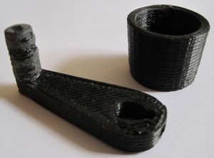
Printing a MakerBot

I’ve already pontificated on the idea that if you’ve purchased a MakerBot Cupcake CNC Deluxe kit, you basically get a second MakerBot for half off.  (Spoiler: it’s because you can print a ton of the most expensive parts that go into building a new one).  I don’t know why, but the idea of replacing wooden parts on my ‘bot with printed parts just fascinates me. 1

So, let’s have a list of potentially (and actually!) printable parts:

  • Electronics spacers
  • 3 large pulleys, 1 small pulley
  • Y stage, the entire thing, as a single print
  • X stage, in three large prints (there would be no need for the end caps if the three pieces were designed properly)
  • Insulating retainer ring
  • Printruder
  • Dinos
  • X stage end caps
  • Z stage captive nut guides
  • Z axis rod bearing brackets

Having more printed components for the MakerBot would reduce a lot of work in it’s assembly.  There’s a lot of tiny fiddly bits in the X and Y stages that would become obsolete.

Heck, it might even be possible to replace some of the bolts with some kind of printable fastener system.

  1. Cue Johnny Cash singin’ One Piece At A Time []

MakerBot Hacking: More build space?

If you got a totally different set of lasercut body panels and larger threaded/precision rods it would be a snap.

But how would you get more build space out of your MakerBot without a big structural change?

I’m not sure how I would go about it – but I suspect I would start by fiddling with the Y stage.  As the smallest stage I suspect it may be the bottleneck.

C is for Catalyst

I purchased the MakerBot Deluxe Cupcake CNC kit – which came with plenty of tools and TONS of plastic.  The Deluxe kit came with things that you’ll need to operate your MakerBot such as the USB2TTL cable, power supply, and ethernet cables.

However, the wrenches and hex keys could be reused to build another ‘bot.  Parts printed up on a MakerBot could be used to print several very useful, and sometimes expensive, parts for another MakerBot.  The plastruder toolhead is $125.00 without the circuit board.  If you could print up the dinos, printstruder, idler wheel, and insulating retainer ring, you’re replacing all of the lasercut acrylic parts ($50.00 at MakerBot).  A persistent person could even replace all of the plastic spacers, wooden or plastic pulleys, the various wooden holders (Z rod caps, Z stage guides, X end rod caps), and probably even the  entire Y stage with printed parts. 1

Heck, if you had all of those parts you would basically just need a box in which to install them all.

Hmmm.  Anyone feel like designing a printable Y stage?

  1. In fairness, the Y stage would have to be printed up in several pieces due to size limitations. []

Differences between MakerBot Batch 9 and 10

Someone recently posted on the MakerBot operators group that there were some minor steps missing on the MakerBot Batch 10 instructions.  Just so you know the three things that person pointed out were fixed almost immediately.  You’re NEVER going to get that kind of service from IKEA.

In any case, this gave me the idea of perusing the Batch 10 instructions to see how they differ from my Batch 9 ‘bot.  Here’s what I’ve noticed:

  1. Different build order.  The Batch 9 ‘bot instructions show the body being built first, then the XY stage, then the plastruder.  Batch 10 shows the XY stage, then body, then plastruder.  I think you could probably build the Batch 9 ‘bot in the Batch 10 order without a problem.
  2. Different Y stage caps.  Batch 10 ‘bots appear to be using an Y stage cap that has more room for the pulley that rides on the Y stage.  My guess is that this will probably buy you a few precious millimeters of print space.  (The pictures say X stage end caps…  but it looks like the Y stage to me.)
  3. Different Y stage pulley.  Unlike my batch 9 bot, these instructions show assembly with a manufactured toothed idler pulley.  I have no idea what benefit is conferred by having teeth on that pulley.  Perhaps it is less prone to slipping on the belt?  Perhaps it makes it easier to tension the Y pulley without disassembling the Y stage?
  4. Different X axis pulley.  This manufactured toothed idler pulley looks similar to the one on the Y stage.

Why the toothed idler pulleys?

MakerBot Build Status

The body is painted, bolted together, rods have been cleaned, XY stage installed, boards soldered and bolted on, cables run.1  I’ve affixed the opto-endstop triggers on the X and Y axes.

  • I have not installed the Z axis endstops mostly because I’m just not that keen on marring that beautiful clear acrylic sheet that is the Z stage.  I’ve created a little fitting out of balsa wood that will eventually support the opto-endstop triggers.
  • I’ve assembled the two “dinos” but not any other parts of the plastruder.
  • I need to assemble the rest of the plastruder, drop it in, and fire it up!
  1. Even if the opto-endstops are going to the wrong max/min ports for the moment. []

One step forward, two steps back

As I mentioned, I had installed the Z-axis threaded rods without actually cleaning them first.  It wasn’t that bad to undo the caps, pull them out, and clean them.  In fact, it was kinda fun.

The process involves covering one end of the threaded rod with electrical tape to protect the threads and your drill, inserting that end into an electrical drill, adding 3-in-1 oil to the rod, and running the drill while holding a paper towel to the threads with a thumbnail.  It worked great and went much easier than I thought it would be.  I also used this opportunity to lower the threaded rods into the lower section of the MakerBot.  I’ll need to make sure they don’t get caught on any wires, but that will be all part of the process of zip tying all of the wires down anyhow.

Since I was going over things I had already done, I went ahead and also tightened up the Y-axis pulley.  It’s kind of a pain to adjust once the XY stage is installed, but I happen to have a very small adjustable wrench that was able to reach underneath the XY stage.

Things I learned while assembling my MakerBot

I’ve assembled quite a lot of my MakerBot today.  This entailed assembling and putting together the X axis stage, Y axis stage, pulleys, putting gears on stepper motors, mounting gears, putting in the slider rods, Z axis threaded rods, bolting on the motors, and assembling the two “dinos.”

  • If you’ve got a Batch 9 MakerBot, definitely install the Z-axis after assembling the body of the MakerBot.
  • Put off adding the Z-stage/extruder-stage for as long as you can.  It will just be in the way.
  • Keep that sandpaper handy – you may need to sand down some tabs or widen slots or holes to make things fit, especially if you painted your MakerBot.
  • If the smooth slider rods are just a smidge too short, they will slide back and forth causing a little extra noise as your MakerBot operates.  I haven’t gotten mine running yet, but I have read this is the case.  I noticed that one of the slider rods for the X axis on my Batch 9 MakerBot was about 1mm too short.  When I put the caps on, I noticed that it still had some wiggle room.  I took a scrap of paper towel, folded it up so that it would push up against the end of the rod, and clamped it down.  There’s no wiggle room now, so hopefully that’s it.
  • Make sure the top bearing is just under the top edge of the top panel.  This is in the directions, but it’s really important to make sure everything spins freely.
  • Putting gears on the stepper motors is tough!  Even when you back the tightening screws on the gears out as much as you can, the fit is incredibly snug.  I eventually sanded the inside of the gear slightly, put the motor on cardboard, and then pushing downwards slowly and forcefully.
  • When you’re installing the geared belts, get them as level as you can manage.
    • For the top stage this will involve adding/subtracting washers/nuts from the printed pulleys as well as adjusting the gear’s placement on the stepper motor.
    • For the X and Y stages, the height would essentially be dictated by the height of the belt on the clamps.  The height of the belt on the clamp is essentially set, so the pulleys and gear on the stepper need to be matched to that.
  • When assembling the carriages with the plastic sliders, the instructions suggest you may need to sand the circular hole they fit into.  Just make a point of sanding them, if they’re tight they could affect the looseness of the stage on the rods.
  • Inspect your Y-stage pulley (this is the smallest printed pulley) to make sure the top is level and there are no protuberances.  Even a little bit of a nub will prevent it from rotating properly.
  • The easiest way to remove the itty-bitty sticky-paper protective acrylic cover is to use a razor blade or exacto-knife to pop them off.  You probably don’t need to, but it’s an aesthetic thing.

Building a robot that builds things

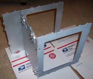
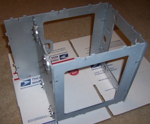
Once the painted parts were dry, I couldn’t resist getting started bolting the thing together.  Putting the parts together is pretty fun – it goes quickly and all the parts fit together very well.  In fact, it went so quickly that I didn’t get pictures of each step as I was originally planning.  Oh well, I guess you’ll just have to build one for yourself.  ;)

Behold!  A robot being born!

Front, middle, back, and Z-axis brackets bolted on

Front, middle, back, and Z-axis brackets bolted on

And now…

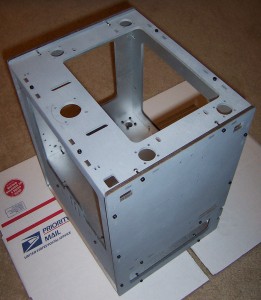
The top

The top

Here the body panels are mostly all put together.  You’ll notice I opted to install the Z-axis threaded rods after assembling the body.

Sides, top, bottom all bolted together

Sides, top, bottom all bolted together

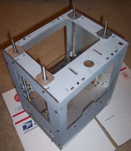
The new system is really huge improvement over the prior.  Before you had to get all of the Z-axis rods identically assembled and installed.  Now I just had to set them up, drop them in, make sure the top of the topmost pulley on each rod was just below the level of the top panel.  Any higher and it would have interfered with the smooth rotation of that axis.

Z-axis installed

Z-axis installed

The Z-stage is also a huge improvement over prior designs.  Since the new brackets are “U” shaped, you can remove the entire stage without having to unbolt the entire assembly.  It’s also possible to adjust one or more rods individually by lifting the stage on that side slightly and rotating the hex nut as required.

I feel smarter just having seen these designs in action.