I just had OpenSCAD die on me. It’s probably my fault for running a version from 2024 – but it’s been super stable and … why mess with a thing that works? Fortunately, OpenSCAD replied to my toot saying “@makerblock Check the “Backup Path” folder, e.g. on Linux that is at $HOME/.local/share/OpenSCAD/backups/”
However, having a program crash isn’t always that bad. Yes, it’s a hassle. But, I often find that the new version ends up being built / recreated in a fraction of the time and and more streamlined. In this case, I was working on a revision of my stamp eraser carving grips. The code for new version ended up cleaner and the final model was better looking as well.
A friend recently requested some less LLM-centric content. I’ve often said this blog is largely a lab notebook for various ideas or build log. It’s also merely a subset of the stuff swirling around in my brain than a dedication to any one topic. In any case, this post is dedicated to Pete.
I saw the above 3D printed box on Instagram. It looks like a wanted poster from the show “One Piece” of a character named Roronoa Zoro who carries three swords. The box contains a small post in the very center which seems very out of place – until the lights are dimmed and the light under the tip of the post is activated, revealing the light is blocked by the irregular edges of the box and casts a shadow of the silhouette of a figure holding three swords.
I’ve seen other implementations of this stereographic projection technique, but this was easily the coolest. The disparity between the size and shape of the box and shadow was almost startling.
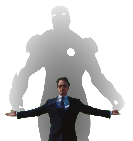
My mind went wild with ideas upon seeing this box. One of the first ideas I had related to some fan-made movie posters by Kevin Collert many years ago.1 Imagine a small projector / box of arbitrary shape that could project that kind of silhouette behind you?
Yeah, a Tony Stark cosplay is neat… but what if you had an inconspicuous stereographic projector on your back that threw up a huge Iron Man shadow behind you!?
This could be extended in any number of ways. A Luke Skywalker cosplay that casts a Darth Vader shadow, Bruce Banner with a Hulk, etc, etc. But, also, what about a shadow of a familiar? A little dragon perched behind you. Or two thugs standing to your side like evil shadow henchmen? Or a crowd of zombies? The neat part about the box / lamp shown on Instagram was that the box didn’t look like it would display that kind shadow of a shadow. It just looked like a box with weird edges to it.
But, how did they do it?
He makes a good point (iykyk)
I’m terrible at Blender. I’ve watched tutorials, tried to use it, but I just can’t wrap my feeble mind around it. My one string is the ability to make things in OpenSCAD. There are plenty of others who can make incredible things in it, but I’m no slouch. The code may not be pretty, but, well, as they say…
And, really, that’s all that counts
I started with a few assumptions.
The light source has to be a single point. If there were multiple LED’s or filaments, it would create fuzzy / duplicate shadow edges. This should be possible with a single bright LED.
The shadow is basically a cone. The edge of the shadow everywhere must be essentially some sort of a distorted cone, with the center point being the single point of light and the edges of the silhouette being the edge of the cone.
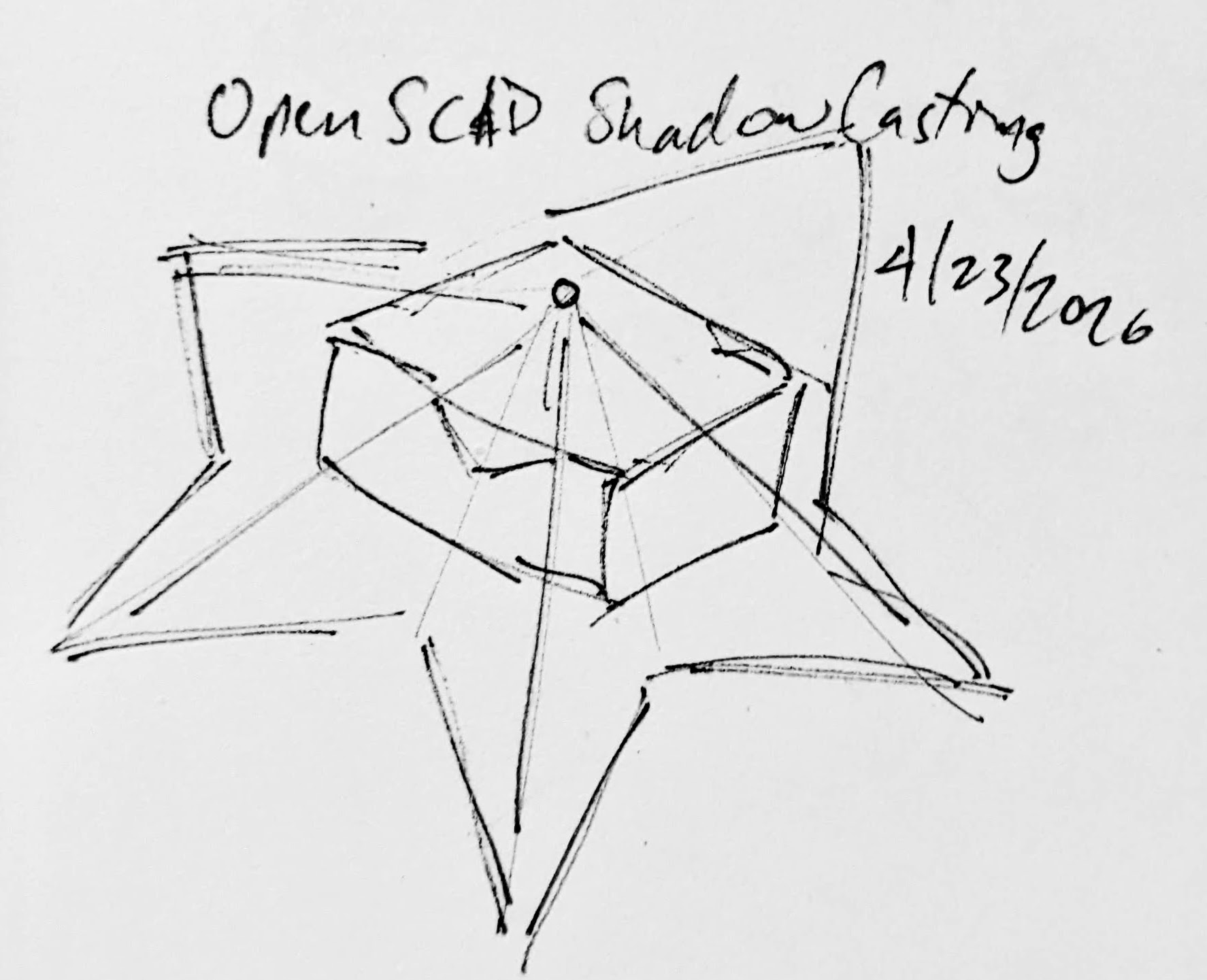
The top edge of the box must be where the cone intersects with the box. If we decide how far off the wall the point of light is and we know where we want the shadow to be and where the shadow edges are, we should be able to intersect the shadow-cone with a thin walled box.
A rough sketch of the idea
Creating the box itself shouldn’t be that big a deal. It’s an easy few lines of OpenSCAD. Creating the arbitrary “cone” was initially a much harder problem. Now, if the design I was trying to create was very simple or entirely convex, I could just use the OpenSCAD hull function around an SVG of the desired shadow and a very small sphere for the point of light. Since a simple shape would be uninteresting, I knew that hull wasn’t going to work. For a while I tried really hard to build a python program that would work by creating a polyhedron built out of the large SVG in the desired location and a very small SVG at the light point – and stitching the sides together programmatically. If you’ve ever worked with the OpenSCAD polyhedron functions, you know what a pain it is. If you don’t define the faces in a certain order or order the faces properly, you’ll end up with flipped faces and a pile of useless triangles. Even when the faces were properly built, the result ended up being difficult for OpenSCAD to render since it involved so many points converging on so few points and weird little overlaps. It was a mess.
I’m listening…
You mean, all I have to do is RFTM? Apparently the linear_extrude function has a parameter called “scale” where you can define how small something should get as it is extruded. This is literally exactly what I needed.
I needed the shadow on the wall to be extruded off the wall as high as the point of light, but scaled down to that same point of light. But, would this work??? I haven’t printed it yet, but I believe it should.
This slideshow requires JavaScript.
From there, the next question is… does this OpenSCAD back-of-the-napkin sketch really work? Again, I’m not sure – I haven’t printed this for a few different reasons. If this design were printed “as is”, there would be a ton of overhangs and support material. I believe when you look at some of the pictures of the lamp lit up from the side, you can see the infill patterns on the sides. I can’t tell from these videos – but I suspect the easiest way to 3D print this box would be to do so in big flat panels. At the point you’re just trying to turn filament into 2D panels, why even bother printing it when you could lasercut it in a fraction of the time?
Let’s look at a few stills of the lamp.
This slideshow requires JavaScript.
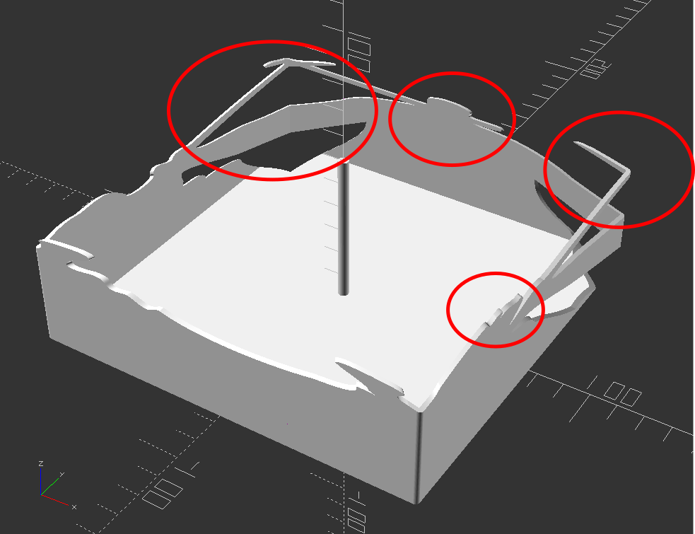
Now, for my quick mockup I just used a simple square shape – but you can definitely see the same features as in the lamp in the video stills. The head, the crossed sword tips at the left, the jagged edges on the bottom right, the floating sword on the right.
Common structural features circled
Given that the theory feels intuitive and sound and that my quick mockup proof of concept seems to have the same structural features as the lamp in the video… this seems like it would work.
If this quick mockup works, then why restrict ourselves to simple boxes? For a mass produced thing you just want to stamp out, a simple box just makes sense. You could lasercut the panels, slap them together, and churn them out all day long. But, the thing that you use to block the light and form the shadow could be any arbitrary shape. It could be a triangle, star, or something far more complex. Here’s another quick sketch:
This slideshow requires JavaScript.
Obviously, this would be a support structure nightmare. But, for a one-off project and a cool enough idea, I think it could definitely work!
His work has been stolen and slapped on so many dropshipped things that it was very difficult to find the original artist! [↩]
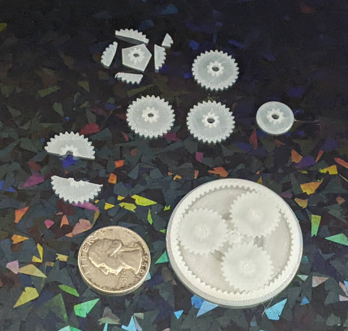
I designed a planetary gear assembly, more to see whether parts this small would even turn out than to actually make a working component. The gears are about 3 mm thick, but half of that is the larger part. I forgot that you can’t have a two-level gear mesh against another identical gear, so these didn’t move at all.
A test planetary gear assembly
I reprinted the parts, this time increasing the center hole size and also removing the teeth off the larger side. It kinda works, but it’s very finnicky. This might be a side effect of these gears being very thin and the teeth very small. I think it’s probably worth sacrificing gear ratio in favor of larger, more consistent teeth.
Small improvements
The OpenSCAD code is a mess, lots of vestigial code remains, lots of non-working parts are commented out, and it all just needs more comments in general. I hate looking at it. But, as one of my favorite memes goes…
I was flipping through my smaller notebook and remembered I’d already posted about a credit card sized design for a protractor and ruler. I decided to connect this to my recent other design and turn it into a short series. This design predates the one I most recently made and shared on this site, thus the title.
While I posted a writeup to Instagram, for some reason I didn’t put anything here?! Other websites go away over time and even if mine doesn’t last forever, well, at least it’s still mine. Thus, here’s the photos:
This slideshow requires JavaScript.
And, just in case1 Instagram completely evaporates, here’s the writeup I posted:
A DIY protractor / ruler / template card.
I needed a quick and convenient way to make straight (ish) lines and angles that I could keep in my small notebook.
The little card is about the size of a playing card and acts like a 5mm increment ruler, 10 degree protractor, and can make it easy to draw a grid.
This all started because I was working on an electronics project, needed some resistors and haven’t memorized the color chart, decided to draw a color chart in my notebook, needed a grid / ruler, decided to design my own after seeing a neat metal one on Kickstarter.
My solution is basically to make a solid for the thin brim + tall cutting edge and then subtract the original SVG shape. I tried it with each of @raster’s SVG’s for the teddy bear, cloud, hexagon, and pacman and they seem to work. Anyhow, here’s the code I wrote instead of doing the work my employer pays me to do:
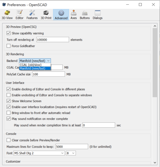
After mentioning long render times on my machine, @raster suggested switching to the manifold 3D rendering backend. Depending on your OpenSCAD version, you might need to poke around to find how to enable this option. It’s absolutely worth your time and should really be enabled by default.
Emmett’s manifold library dropped the render time for one of my designs from 300 seconds to… under 8 seconds. I literally used to avoid hitting F5 on more complex designs or avoid cranking up the facets so I didn’t have to wait for long renders. A single comment from a friend, telling me about an option written by another friend, has completely and permanently changed how quickly I’m able to iterate and design objects forever.
Here’s how you can instantly save tons of time with your OpenSCAD designs:
Thanks to @raster, I’m going to do a side-by-side taste test of several different flavors of OpenSCAD.1 To give each one a similar test, I’m trying out my D-Pad design from … uh, earlier this morning.2
Obviously, the good folks working on OpenSCAD have dramatically improved preview/render times over the last four years. The speed boost in using a later snapshot is pretty significant if you’re doing any kind of complex designs. They must be using some kind of cache system to make the render times so fast.
The speed differential between 2024.01.13 and the latest snapshot is so slight, I’m not going to switch things up unless I bump into a design that struggles with rendering some complex feature.
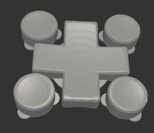
This week’s topic related to @deshipu’s directional keypad designs. The directional pad is clearly the most complicated part of the design. The four buttons are basically just cylinders that can be created in several different ways.
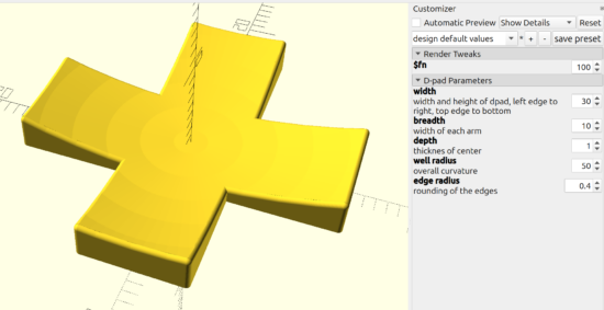
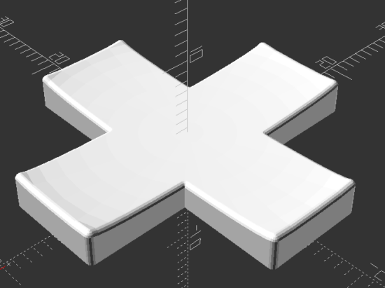
After staring at the design a little longer, I changed from my original design idea to creating a 2D cross, extruding that, subtracting out the curved area described by a sphere (a homebrew hack I’ll describe below), using the minkowski function to surround the entire surface with a small sphere to give it a rounded look, then cutting the bottom off to ensure it is flat. I didn’t include a flat cylinder as in the original design above, but that’s a trivial addition. The downside? This is a 5 minute render on my machine, largely due to the minkowski function.
You’ll notice I use “offset” to reduce the size of the directional pad, because I knew I was going to round it all with the minkowski function in a few lines.
The directional pad is actually just a rectangle, run through a for loop once to rotated it by 90 degrees, before being extruded to the specified height.
The last two lines of code are used to create a large cylinder, larger than what I knew the pad would be, then mirrored in the Z axis to cut everything below the XY plane.
As in prior designs, I pre-define “fn” to be a “pow(2,5)” so that I can use a low exponent to iterate designs quickly, then crank it up for a detailed design.
The hack I use the most often here, and the one I’m the most proud of, is where I make a sphere like “sphere(r=0.5)” and then scale it by whatever I need. Since the sphere has a diameter of “0.5” mm, the actual sphere is 1mm in diameter – so when I scale it in the XY by 30 and in the Z by 2 (since the edges of the keypad are 3mm tall and the center is 1mm tall), the diameter is now 30mm and the height is 2mm. This little trick, of being able to scale a sphere to the exact size I need has come in handy countless times.
I’m not the best programmer, not the best at OpenSCAD, but I’m kinda happy that I was able to build this in about 31 lines of code. :)
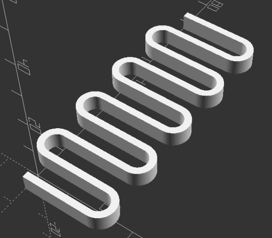
“I’m trying to come up with a good way of creating this in OpenSCAD… I have something using a bunch of hull’d cylinders but I’m wondering if there is a better/easier way to do it.” @rasterweb
A friend posted a design pondering whether there was a better way to design an object in OpenSCAD. As so often happens when I approach a 3D design, one solution pops up in my head… and is immediately discarded as garbage. That first thought was to create a negative of the interior of the spring, then iterate along the length of a stretched cube.
In the end, I opted for1 creating a flat version of a single “loop”, made from differenced hulled circles, repeated over the number of desired loops, then trimming alternating ends (so it wouldn’t look like a chain).
I like to use OD/ID/OR/IR to mean outer diameter, inner diameter, outer radius, inner radius.
I think the “spring_loop” module could be simplified slightly by calling another module which creates each hulled circle, but weighing the additional module code against just retyping a little code I opted for what got it done faster.
I like to specify the facets on circular objects right at the top of the file. This way, I can adjust the smoothness of the object by just changing just the exponent part of the $fn system variable.
Reasonably parametric. There’s some additional further optimization that could be done in the spring alternate end clipping.
Can’t wait to see what @rasterweb makes with a 3D printed spring!
My experiment with a multi-piece turn around didn’t work. The idea was for a multi-segment turn around where each string could be tightened and that portion of the turn around would be able to rotate as needed independent of the other pieces. I simply did not account for the kinds of stresses the pieces would be under through normal use and string tension. Each segment deformed, resulting in none of them being able to rotate and the slightly less rigid turn around bowing slightly under the pressure. I couldn’t get a great picture of the deformed parts, but perhaps this will give some idea.
This slideshow requires JavaScript.
In the end, the best result for my ukulele has been a 3D printed turn around, finely sanded smooth, unadorned by paint, with a small amount of lubricant (I’ve used machine oil) over the metal bridge and across the turn around. These simple elements have, hands down, beat the over engineered / over designed pieces above. If they were printed out of a more rigid material, milled or turned from solid metal, created by using a system of washers, or made using a full length bolt, I’m sure it would have worked better.
The design of my turn around uses captive nuts in the plastic core, secured by bolts on either side. This ends up being dramatically easier and cheaper than trying to source very long Chicago bolts and posts – but has a minor downside in that the two bolts don’t actually connect. As long as the material between the two bolt ends is strong enough to withstand the continued forces of four strings under tension, there shouldn’t be a problem. However, even printing the turn around with the best orientation for printing strength in PLA didn’t result in a part that could withstand these forces for a long time. 1 One of my ideas for this part involved using bolts that were possible slightly longer or of different lengths so they would both tighten slightly into the same captive nut, resulting in one “continuous” piece of metal for the turn around core, then using washers to ensure / assist in minor distance adjustments.
Here’s how it looks today:
This slideshow requires JavaScript.
I don’t plan on any more improvements for this particular ukulele. I’ve deeply enjoyed playing it since it became “finished enough” to be playable in August of 2022. That said, I’ve been thinking about how I would create another one.
CNC Cut Wood. I spent the vast majority of the time on this project just rough cutting the wood to size using a combination of hacksaw and coping saw blades. I spent a ton more time shaving wood off the neck using rough files. Starting with a piece of wood that was already the approximate dimensions and only needed finishing would feel like starting at the 90% mark.
Different Wood. I went with mahogany for a variety of reasons – but cost was one of the biggest and dumbest of these. The difference between a plank of mahogany for $10 and the most expensive wood from Rockler at maybe $30 is a rounding error when the project took more than 100 hours of my time. I’ve suggest that wenge, zebrawood, ironwood, or walnut would be my choice for another attempt. Of these, I am leaning towards walnut for a deep brown, possibly gray finish.
Strap Attachments. The strap was not quite an afterthought. I had always planned on using nylon webbing / seat belt material for the strap and had designed printed strap buttons for hooking the strap onto the ukulele, but in the end I just couldn’t bring myself to drill holes in the finished uke. This was just as well since I had wanted to try using some paracord in a project for a while. After using a flame to seal the ends of the paracord and webbing, the result was way too thick to use in my sewing machine and had to be hand stitched. I’m not great at hand sewing, but it is functional. Given the dark colors of the thread, paracord, and webbing, the haphazard stitching isn’t very noticeable. If I really took my time with it I might be able to do a better job. If it came to that I might want to use some silver or light gray thread to add a little pop.
Acoustic Improvements. I’ve noticed a dramatic change in the quality of the ukulele sound when I place a book, empty box, or large piece of rigid cardboard between the uke and myself while I’m playing it. I’ve thought about how this could be incorporated into a new design by creating a system for bolting, attaching, or otherwise connecting a larger section to the ukulele. Another incredibly interesting option is the plastic sheet used by TitchTheClown. He used thumbtacks to secure a sheet of plastic from a soda bottle against the ukulele, then a heat gun to tighten it into something like a drum surface.