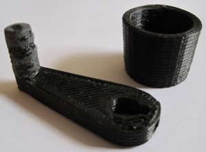
The mini-mug came out looking fantastic. The Z-stage crank was actually my third print. The handle got a little … blobby so you can see where I sanded it down.
Monthly Archives: December 2009
MakerBot Raft Settings
I was having some trouble getting my rafts to stick to the build platform until I did the following:
- Switched to the acrylic build base (which I promptly pock-marked with a hot extruder)
- Changed the Skeinforge raft settings to those suggested on the Thingiverse blog
If you’re having raft trouble, do both of the above and don’t look back.
More calibration
Calibration is proving to be a relatively slow process. As you can see from my prior post, my prints are drifting towards the back of the MakerBot. This appears to be due to either improper tension, the power being set too low for the Y stepper motor, and/or the Y axis rods not being smooth/oiled/straight enough. Given that the first few layers are spot on, I suspect it is a stepper board power issue. The Y axis motor is easily the first quietest of the three axes. As the X axis motor is the nosiest, I could probably dial it back without an effect on performance.
To do for tonight:
- In the hopes of diminishing the Y axis drift problem
- Oil the Y (and X and Z) axis rods
- Check the Y (and X) axis slides
- Dial up the Y axis power by turning the potentiometer on the Y axis stepper board clockwise
- In the hopes of diminishing operational noise
- Dial down the X axis motor slightly
- Dial down the Z axis motor slightly
Test prints 3 and 4
Heater barrel – backasswards?
Dangit. According to the very latest changes to the MakerBot assembly wiki, I put the heater assembly together with the heater barrel upside down. I’m not entirely sure what this means for my heater. Clearly it was working well enough that I could extrude reasonably well.
The questions is – do I leave it as is or disassemble/reassemble?
If I leave it as is, I suppose there’s a chance I could bulge the insulator, ruining it.
I’ve already disassembled/reassembled once because of a bad thermistor connection. If I disassemble again, I’m thinking the ceramic tape and nichrome may have had it. Not to mention that I’m probably going to have a royal mess of plastic inside the barrel and nozzle to clean up.
First and second test prints
Well, I’m trying the traditional mini-mug!
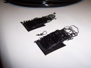
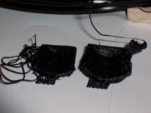
Something tells me they’re not watertight. The first one (left) snapped off the foam-core raft part way through the build. The second one (right) got all gloppy and then snapped off the foam core raft part way through the build.
Except for the fact they’re not even close to done, the adhesion between the layers seems pretty good. The raft on the second one was a little gloppy which caused me to be a little apprehensive throughout the build. After a few layers the gloppiness evened out. However, it cropped up again, accumulated, got super gloppy, and ruined the build.
Suggestions?
Extrusion!
My first hack
Seeing as how I already had the heater in pieces, I figured it couldn’t really cause that much harm to move the plastruder board. I totally get why the MakerBot guys put the board on the extruder – that way all you had to do was swap out an extruder and you can roll with a totally new print head.
I don’t really intend to do printing beyond single color plastic. This may very well change if we see a support material extruder being offered. But for the foreseeable future, I am really looking forward to printing away with my giant coil of black ABS.
That said, I’m not attached to the idea of having totally modular heads. 1 On the right side of the MakerBot there’s a really large area above the motherboard and to the left of the three stepper motor boards. The only things preventing the plastruder board from being mounted right there are (1) the motor wires are too short and (2) four holes in the body.
I had dissected a piece of ethernet cable for the wires running to the nichrome wire and thermistor, so I still had four wires left. I used another two and a bit of solder to extend the wires to the extruder motor.
Sometimes when I need to drill a small hole through soft or thin material I don’t even bother with the drill. I used a small drill bit with a rubber band wrapped around the non-drill-bitty-end to give it a grip and rotated it into the right panel of my MakerBot. Bolt it on and…
Presto! Now I can see all the way through the plastruder. :)
- Sorry about the pun. [↩]
With a little help from my friends
Thanks to the kind folks at the MakerBot Operators Group I’ve been diagnosing what’s going on with my Y axis stepper board and plastruder.
1. Y Axis Stepper Board
No matter what I was doing I couldn’t get the Y axis stepper board to respond to any commands. Also, the power light on the board would light up as the MakerBot powered on – however it would immediately dim to nothing. I swapped out every single cable, the motor, and it was always the Y axis board! Finally, I completely pulled the board off the ‘bot, pulled every cable, and started adding the cables back one by one… and it worked!
I was concerned with why it wasn’t working, but happy it was working. So, I bolted it back on, connected the wires… and it didn’t work any more! What went wrong? It was one of the opto-endstop cables. I discovered that when I connected the front opto-endstop cable it would kill the power to the Y-axis board – or any other board!
The Y-axis three prong cable is easy to insert upside down. And that’s what I was doing – because it fit better in that orientation. Well, flip it upside down and rock on!
2. Plastruder / Extruder Temperature 0.0
Now that I could manipulate the 3 axes, I tried to use the plastruder. I noticed that even at room temperature the thermistor was reading 0.0. Also, the heater was smoking a little, I could smell something burning faintly, and the extruder was oozing something clear and sticky. Not ideal.
With a lot of help from the guys at the MakerBot Operators Group I attempted to diagnose the problem. Here’s what I tried:
- Testing the resistance of both the nichrome and thermistor while both were still plugged into the plastruder board. Both seemed okay – but I still could not get a reading from the thermistor.
- One suggestion was to plug a random resistor into the thermistor ports to see whether the board and software was receiving information. Being a complete novice and having zero spare parts around, I actually had to make a trip to the local electronics store for a single resistor. 1 Once plugged in the resistor (a quarter watt 10k) must have been resisting stuff because the board interpreted it as a temperature. Thus, the board and software are probably fine. 2
- Thus, I disconnected the heater wires and thermistor wires and tested them away from the board. I really should have done this in the first place. It would have told me that the thermistor was either burned out or no longer connected to the wires.
- Taking the heater apart was almost painful. The ceramic tape was a little scorched, parts of the kapton tape closest to the print head were actually burned to a blackened crisp and flaking off. It was just not pretty.
- The nichrome seemed to still be intact and giving the proper resistance, but the thermistor was not showing connectivity. I was pretty bummed that I may have cooked it. But, when I started to peel that tape away, I tried to test the resistor leads – which did show the proper resistance! I checked the connections between the thermistor leads and the solder and discovered that one of the leads had lost its connection with the solder/wire.
- I then tried to resolder the wire to the thermistor and then rewrap it into the kapton tape and tried its resistance again – and got a proper reading. Then I taped it to the extruder head, to see if I could get a heat reading off of it – and I did!
- This time, I went VERY slowly. I tested the heater/extruder head completely apart from the printing assembly with the thermistor taped to it – I could heat and read the temperature. I then wrapped it in tape, tried again, success again. Then I wrapped it back in the ceramic tape, heated/read again with success. Then I put the assembly back on the plastruder, heated/read again.
- Now, a decision I made that I may very well regret later was to leave the nichrome wrapped as it was and not pull it all off and rewrap it. The testing showed it was intact, it was still in its fiberglass insulation, and I had done a pretty good job of wrapping it in the first place. In rewrapping the heater I took out as much of the burned kapton tape as I could and then wrapped it back up.
- I picked up a lot of other stuff while there, but this a single resistor was the actual purpose for the trip. [↩]
- Thanks Rick Pollack! [↩]
Pulley troubles
My MakerBot (Batch 9) uses printed pulleys. I had attached them to my MakerBot with the bolt going down into the body with a nut underneath. As far as I can tell, there’s only two ways to attach the printed pulleys to a ‘bot:
- Bolt going down into the ‘bot, nut underneath and inside, pulley with the tapered edge on the top.
- Bolt going up from underneath and inside the ‘bot, nut on top, pulley with the tapered edge on the bottom.
The problem with this orientation is that the pulley can slip down on the bolt. When this happens it’s very easy for the belt to gradually ride up the tapered edge and then right off the pulley. This ended up killing one of my test prints as the Z-stage started to descend to start the print. Because of the way the “tapered end up” orientation of the pulley rides on the belt, I don’t think sanding away the taper would totally remove the problem.


