Thanks to the kind folks at the MakerBot Operators Group I’ve been diagnosing what’s going on with my Y axis stepper board and plastruder.
1. Y Axis Stepper Board
No matter what I was doing I couldn’t get the Y axis stepper board to respond to any commands. Also, the power light on the board would light up as the MakerBot powered on – however it would immediately dim to nothing. I swapped out every single cable, the motor, and it was always the Y axis board! Finally, I completely pulled the board off the ‘bot, pulled every cable, and started adding the cables back one by one… and it worked!
I was concerned with why it wasn’t working, but happy it was working. So, I bolted it back on, connected the wires… and it didn’t work any more! What went wrong? It was one of the opto-endstop cables. I discovered that when I connected the front opto-endstop cable it would kill the power to the Y-axis board – or any other board!
The Y-axis three prong cable is easy to insert upside down. And that’s what I was doing – because it fit better in that orientation. Well, flip it upside down and rock on!
2. Plastruder / Extruder Temperature 0.0
Now that I could manipulate the 3 axes, I tried to use the plastruder. I noticed that even at room temperature the thermistor was reading 0.0. Also, the heater was smoking a little, I could smell something burning faintly, and the extruder was oozing something clear and sticky. Not ideal.
With a lot of help from the guys at the MakerBot Operators Group I attempted to diagnose the problem. Here’s what I tried:
- Testing the resistance of both the nichrome and thermistor while both were still plugged into the plastruder board. Both seemed okay – but I still could not get a reading from the thermistor.
- One suggestion was to plug a random resistor into the thermistor ports to see whether the board and software was receiving information. Being a complete novice and having zero spare parts around, I actually had to make a trip to the local electronics store for a single resistor. Once plugged in the resistor (a quarter watt 10k) must have been resisting stuff because the board interpreted it as a temperature. Thus, the board and software are probably fine.
- Thus, I disconnected the heater wires and thermistor wires and tested them away from the board. I really should have done this in the first place. It would have told me that the thermistor was either burned out or no longer connected to the wires.
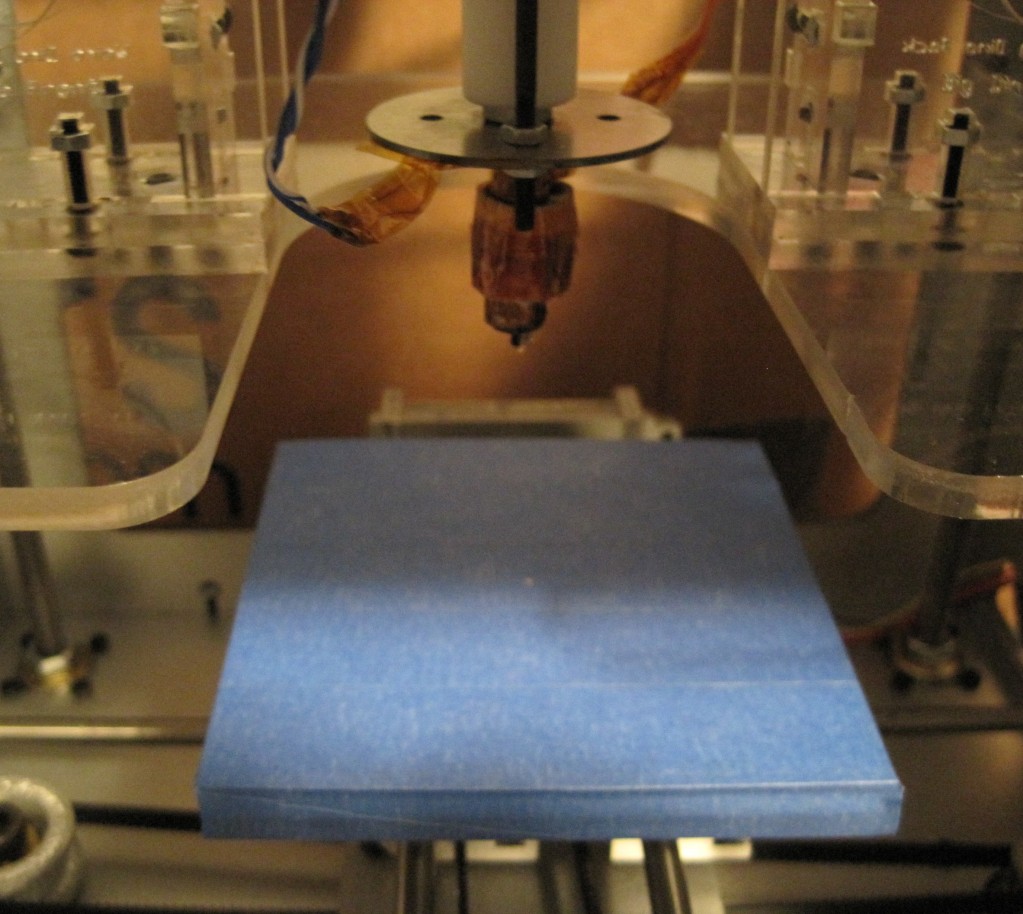
- Taking the heater apart was almost painful. The ceramic tape was a little scorched, parts of the kapton tape closest to the print head were actually burned to a blackened crisp and flaking off. It was just not pretty.
- The nichrome seemed to still be intact and giving the proper resistance, but the thermistor was not showing connectivity. I was pretty bummed that I may have cooked it. But, when I started to peel that tape away, I tried to test the resistor leads – which did show the proper resistance! I checked the connections between the thermistor leads and the solder and discovered that one of the leads had lost its connection with the solder/wire.
- I then tried to resolder the wire to the thermistor and then rewrap it into the kapton tape and tried its resistance again – and got a proper reading. Then I taped it to the extruder head, to see if I could get a heat reading off of it – and I did!
- This time, I went VERY slowly. I tested the heater/extruder head completely apart from the printing assembly with the thermistor taped to it – I could heat and read the temperature. I then wrapped it in tape, tried again, success again. Then I wrapped it back in the ceramic tape, heated/read again with success. Then I put the assembly back on the plastruder, heated/read again.
- Now, a decision I made that I may very well regret later was to leave the nichrome wrapped as it was and not pull it all off and rewrap it. The testing showed it was intact, it was still in its fiberglass insulation, and I had done a pretty good job of wrapping it in the first place. In rewrapping the heater I took out as much of the burned kapton tape as I could and then wrapped it back up.


