I’ve extolled the virtues and pitfalls of running a software as a service business. ((Photo courtesy of Rufus Gefangenen)) This morning I discovered a glitch in my SaaS website that, while it doesn’t cause anything to actually malfunction, creates a very obnoxious problem on a lot of the pages. The site is written in WordPress1 and the entire SaaS component of the site is built out of plugins.23 Basically, one of the plugins creates a form that is used in one of the pages. The malfunction is that the form is now included on every page. Ugh. This is going to be a really fun bughunt because even when I disabled every single plugin, the problem persisted. Apparently the glitch started appearing about a month ago – when I last updated WordPress.
Now, I’ve been meaning to just rewrite the plugin from scratch – but I’m also keenly aware of the pitfalls. My biggest incentive to rewrite the code is so that it is more future-proof. Another reason to do it is that the original code was written in such a cludgy manner I’m literally ashamed to tell you how it is implemented. Let’s just say that I originally wrote the core of the plugin after having learned the basics of PHP programming only a few months prior.45 About nine months later, I shoehorned the same code into a WordPress plugin – when I had only been using WordPress for about two months and knew almost nothing about plugins. Now, more than five-and-a-half years from the day I launched the site, I do feel I’m a much more capable PHP programmer and WordPress plugin writer. Confident in my abilities to do a better job and facing the task of having to go through a potentially big bughunt anyhow, some part of me wonders if it wouldn’t be best to just rewrite the damn thing anyhow.
If you’re just tuning in, I’m building an Arduino powered drawing robot. If you’re the least bit interested in making one of your own1 then please take thisquick DrawBot poll to let me know what you’re interested in. You can come right back and check out all the nifty little details in my drawing robot project, promise.
Okay! I’ve finished designing, printing, and installing all the plastic parts necessary and wired up all the bits that need to be wired. Despite the big curl of rainbow colored ribbon cable, which I left in because I didn’t want to measure the cable for an exact fit and because it just looks pretty, the wiring is extremely simple. Each of the stepper motors I’m using has four leads which, through some connections and cables, make their way to the PolargraphSD case. Once these eight wires are connected and the robot supplied with power, you’re ready to start drawing.
Wiring detail
To help tame the wiring mess I lightly braided2 the motor leads and added a drop of hot glue to keep them in line. I made sure I left more than enough slack so I can remove the motors and move them around. On the left side of the above photo you can see a curved piece of plastic. I’m using an old version of one of the monofilament spools to somewhat contain the rainbow ribbon cable.
Wiring and connectors
As mentioned above, the wiring is exceedingly simple – four wires from two motor are connected to eight terminals on the circuit board. Insisting on the rainbow ribbon cable as I did simultaneously complicated and simplified this project. The simplest possible solution would have been to wire the right side motor directly into the terminal blocks on the circuit board, solder four wires to the four left motor leads and plug these newly extended wires into the circuit board and call it a day. It would have involved only four soldered jointed and it would have been a breeze.
But, I had a dream. A dream of a sweet looking awesome drawing robot. And this dream involved soldering 16 separate connections and 8 additional wire ends.
On the left and the right I soldered the motor leads to a 4-pin break away 0.1″ header. Since I didn’t have any brown heat shrink tubing, I decided to color code the motor leads by covering the green lead with a little green heat shrink, the brown with blue heat shrink, the red lead with red heat shrink, and the yellow with yellow heat shrink. If you’re following along at home, alwaysremember to put the heat shrink on the wire before you solder the connection. Once I had soldered the four wires to the 4-pin connector and shrunk the heat shrink, I added a really wide piece of black heat shrink which I shrunk around the whole thing. This way I can easily grab all four wires at the same time. I also think it looks nice.
Before doing this soldering I made sure that I knew the exact order I needed to wire the motors to the circuit board. In case you’re using the exact same setup as me, the colors are, from left to right: yellow, red, brown, green. If I had wired the motors directly into the PolargraphSD board, you would see them, again left to right, as: yellow, red, brown, green, yellow, red, brown, green.
I then took the 4-pin female-to-female connector cable I bought from SparkFun and cut it right down the middle. I took my 10-wire rainbow ribbon cable and pulled away the two least colorful wires leaving brown, red, orange, yellow, green, blue, purple, and light gray. The I soldered the cut ends of one of the 4-pin female connectors to the brown, red, orange, and yellow ends of the rainbow ribbon cable and the other 4-pin connector to the green, blue, purple, and light gray side of the cable.
I spent more than a little time debating exactly how I would include these connectors. Should I solder the motor leads to the female connector wires or is it better to solder the leads to male pins? In the end I decided that if I ever took this project apart I might one day need to change the order of the wires coming out of the motor. If they were soldered to female headers, my only solution would be to add more connectors in between or cut the female connectors off. Since I soldered a 4-pin break-away block to the motor leads, I could theoretically break the four pins apart at a later date with little effort.
I suppose I could have chosen to be slightly less paranoid/OCD about checking and re-checking the wire order when I was soldering. There’s no actual harm in accidentally swapping the order of one of those connections – I could always just swap the appropriate wires going to the terminal block on the circuit board and no harm done. However, it was important to me, for purely aesthetic reason, that the ribbon cable actually look rainbow-y when it was connected to the terminal block.
Besides using one drop of hot glue with each of the motor lead braid bundles, I also added an additional drop underneath the green-through-gray section of the ribbon cable to help keep it in line.
Finished, Mounted Robot!
This is what the robot looks like installed on my wall! I’ve plugged it in and powered it up, but drawing will have to wait for another night. It’s a little difficult to see, but there are four additional plastic parts installed in this picture which were not included in the first picture above. To simply installation and removal, I’ve bolted two white dovetail slides to the wall. Then two black plastic mounts slide onto the remaining dovetail slide on the top of the project box and onto the white dovetail slides on the wall. Tighten a few M3x16 bolts, and everything is solidly in place! ((Just so you know, that the black cord running down the right side of the picture doesn’t really look like that. When I stood back far enough from the wall where the robot is installed, something was in the way which I didn’t want in the picture. When I smudged it out of the way I had to smudge-out the end of the power cord.))
The paper roll seems to unroll pleasantly from behind the project box with just enough resistance so there’s no way it will just unfurl unexpectedly. While it was a little difficult to get started behind the box, ideally I won’t have to repeat the process very often. While I was mounting the project box on the wall I realized that the wall bows out slightly. I don’t think this will affect anything much – it’s just an odd quirk of my home which I noticed for the first time.
I’m very much looking forward to starting a drawing tomorrow. I’ve got several in mind which I’ve prepared in anticipation of Maker Faire. :) While I’ve taken the necessary steps to fine tune the steppers by adjusting the potentiometers, I’m sure they will both need to be dialed in. Even once I’ve gotten a successful drawing done, I foresee additional room for improvement in this project. The pen holder/gondola is a constant source of innovation. I’m looking forward to trying out several designs. I’ll need to install the servo motor so I can do drawings with pen-lifts. Lastly, I think Sandy is hard at work developing the code to support endstops. I think this would be a really helpful addition as it will allow for automatically calibrating scripts to run just before a drawing. Edit: I almost forgot! I also need to experiment with different kinds of pens to find out which ones work best on nearly vertical surfaces.
Don’t forget to take a minute and fill out my DrawBot poll so I’ll know what to blog about next!
Default Series Title
I’ve heard of someone making one for as little as $30 [↩]
Which makes me think “lightly breaded,” which reminds me that I’m hungry, which in turn reminds me that I’m on a diet… Haha! [↩]
My original drawing robot was built using an Arduino Uno, Adafruit motor shield, and two beefy stepper motors bolted onto a big chunk of plywood.1 Now I’m in the process of building a new robot using a sweet wooden project box, a freeduino, a PolagraphSD shield, and the steppers from the original drawing robot. The other day it occurred to me that if I only had another set of steppers, I would have everything I need for a second drawbot.
About a week and a half ago I placed an order with SparkFun for some awesome rainbow colored ribbon cable, wire connectors, and some other stuff. Since I was buying some stuff anyhow, I figured $14 wasn’t much to pay to have another set of motors I could use to rebuild my old drawing robot.2 I also see several additional side benefits to having this extra set of motors. First, and most obvious, I’ll have two drawing robots.345 Second,67 I’ll have another set of motors I can put into some other wacky project down the road. Third, I’ll be able to test a totally different software setup on the second drawing robot without having to disassemble the other robot. Ideally I’d tinker a little with the source for Dan Royer’s Makelangelo’s software and Sandy Nobel’s Polargraph software.
Don’t forget to take a minute and fill out my DrawBot poll so I’ll know what to blog about next!
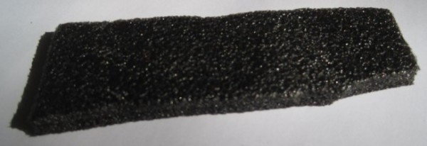
While I understand options like acoustic wool makes a very good sound/vibration insulator, I’d rather not have something that messy in my ‘bot. I’d be happy to use a material that doesn’t insulate as well, as long as it is clean.
I found this short strip of gray/black foam padding lying around my house among my daughter’s things. She had no recollection where she acquired it and believed she might have another piece somewhere. My MakerBot Cupcake CNC came with a large amount of this kind of padding – but it was pink. I didn’t have any of the pink stuff left over, otherwise I would have used it in place of the cardboard as the insulating material for my DrawBot’s stepper motors.
So – do you know the name of this foam padding? Do you know where I could pick up a few square inches of it to use as a sound/vibration insulator for my DrawBot’s stepper motors?
This is going to be another long in-depth post about my Arduino powered drawing robot. If you’d like to know more about how to build one yourself, please help me out by filling out my DrawBot poll. And, if after reading this post you find you want to know even more, be sure and check out the 68 preceding posts about the exact same topic, all listed in order at the end.
While I’m quite happy with how everything has turned out, I haven’t had a chance to fire up the robot and actually try a drawing. Once a few parts arrive from Sparkfun, I’ll be ready to give it a whirl. Until then, please forgive me for not sharing these designs yet. It’s less out of a desire for perfection1 and more out of desire not to strand some poor soul with some flawed printed parts. Thus, I beg your indulgence a little longer. Until then, I’d like to show you how all the bits I have so far work together.2
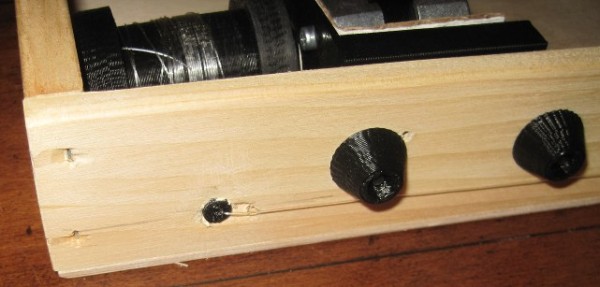
Filament guide and bolt covers
On the bottom left of the above picture you can see the filament guide – with filament helpfully sticking out of it. Just to the right of that you can see two bolt covers/endcaps.
The filament guides ((One on the left, one on the right side)) serve several important purposes. First, the monofilament line does not squeak when running through the smooth plastic filament guide as it does through a hole drilled in a piece of wood. Second, it ensures that the two ends of the filament are always at a constant, precise distance from one another which is important for accurate and repeatable drawings. Filament that is just spooling on and off can change position on the spool by a comparatively large amount.3 Third, the filament guides allow me to make sure the filament is flowing out of the box very closely to the back/bottom of the box – to help keep the pen holder/gondola against the wall. Fourth, they just look nice.
The bolt endcaps serve some practical and aesthetic purposes. Without these endcaps, the M3 bolts on the inside of the project box would protrude outside of the box beyond where they meet the 3mm nuts. The protruding bolts can scratch or puncture and also make the overall project look a little raw. One minor benefit to using these caps is that the force exerted by the bolt and nut as they are tightened against each other is spread out across the area underneath the endcap, leaving less marks on the project box.
For a project that could be easily disassembled, it would be interesting to create a variation on these plastic endcaps that essentially turned them into wingnuts. As you will note from the upcoming pictures, many of these parts were specifically designed to make modular assembly/disassembly/modification a breeze. Having had to pull these parts apart and reassemble them for these photos, I can assure you that taking everything to pieces and putting them back together is a cinch.
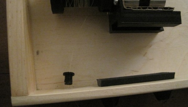
Exposed filament guide and stepper motor rail
In the photo above you will see the filament guide once I’ve pulled it out of the hole in the project box. I believe all I did was drill a 1/4″ hole, design the part to fit, press-fit the guide in place, and run the monofilament line through the guide. I had to re-print these since the first pair was just a little too short. Ideally the guides should just barely stick out from the project box, so that the monofilament never has to come in contact with the wood.
Once I get the ‘bot up and running, I plan to try using some endstops for automatic homing and printing. I’ve seen several drawing robot designs that use metal contacts or simple switches to help the ‘bot automatically home before printing. I think I prefer the style where metal contacts would go around the filament guides at either end, as they are less obtrusive on the exterior of the project box.
Just to the right of the tiny filament guide, you’ll see the plastic rail that I’m using to mount the stepper motors. There are holes in that long plank of plastic with recesses for the M3 boltheads. This rail or track or slide is held in place quite firmly by just those two bolts. Once the rail is in place, the motor mount can be slid back and forth. It’s a tight fit and would probably stay in place by itself, but why leave things to chance? The motor mount includes a bolt and captive nut behind the motor, so that it can be tightened against the rail.
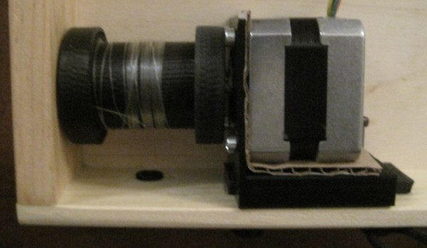
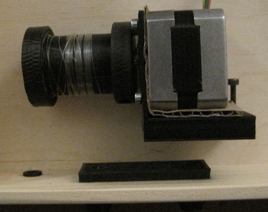
Stepper motor, fully installed
In the photo above you can see the stepper motor completely installed. It’s not much to look at, but I rather like it. You can just barely see the bolt just behind the motor that I use to keep the mount on the rail. The setup is pretty solid and more than enough for the amount minor operational stresses they will endure.
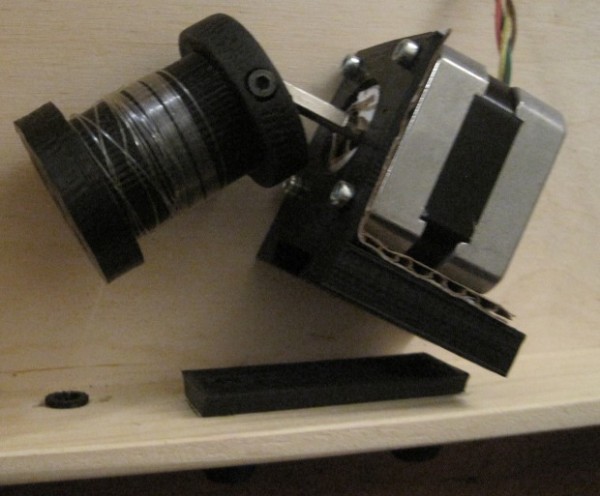
Stepper motor, bolt loosened and off rail
In the above photo you can clearly see the top of the filament guide sticking out of the project box, the motor mount removed from the rail, the loosened bolt I use to keep the mount tight against the rail, and the corrugated cardboard I’m trying out for sound insulation.
Stepper motor off rail and spool off motor shaft
In this view you can clearly see the bolt in the side of edge of the spool I use as a “set screw.” The end of the spool has to be as thick as it is in order to accommodate the captive M3 nut. While the other end of the spool does not have to be nearly as thick, I designed it to be symmetrical.4 You’ll also notice that the spool is not tapered on either end. I designed the spool to be a two-piece bolt-together design. This has the beneficial side effect of allowing me to trap the end of the monofilament line between the two pieces, rather than using a knot in the filament or some other such fix. ((OCD again))
End of spool
Above you can see the end of the spool. This is the part of the spool facing away from the motor. Since I didn’t want the spool to be too unbalanced5 I didn’t want to use just one bolt on one side of the motor shaft. I couldn’t use one bolt down the middle, since it would make the entire spool much longer than necessary. Given that I was trying to make wide-diameter spools anyhow, it was little hardship to add a way to bolt the spool together on each side. The end you see has two hexagonal holes to fit the M3 nuts and the other end has long holes going most of the way through, specifically designed to work with some of the M3x16 bolts I have lying around.
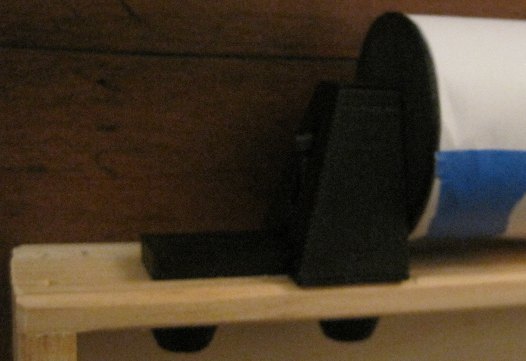
Paper roll mount
The paper roll mount system you see above were actually the first plastic parts I designed and installed into the project box.6 The entire assembly is pretty solid. You’ll notice I used another set of bolt endcaps to keep the bolt threads from sticking into the project box. While I didn’t anticipate them scratching or puncturing anything inside the box, I do really like the way they look.
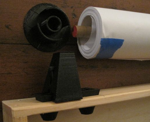
Paper roll mount, disassembled
Above you can see the paper roll mount system disassembled.7 The bolt is simply loosened, allowing the piece of plastic which has a circular hole for the wooden dowel to slide back, in turn allowing the paper roll to be removed easily. You’ll note that the paper roll does not have any kind of cardboard core, as a roll of wrapping paper might. This is why I had to create the thin endcap for the paper roll. It serves to keep the paper roll centered on the dowel while preventing the paper from slipping from side to side. The plastic rail for the paper roll mount is the same exact rail, only slightly shorter, that I used for the motor mounts.
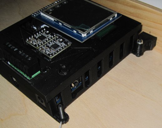
PolargraphSD case installed
When I designed the PolargraphSD case, I was mostly concerned about creating a case that didn’t use a lot of plastic and which could be easily mounted. What I didn’t take into account was how I would end up mounting it to the inside of this particular project box. In the end I had to design two plastic parts that would connect to the PolargraphSD case. The beneficial side effect is that now the entire case is set off from the back/bottom of the wooden project box by the thickness of an M3 bolt head on each of the four corners. It remains to be seen whether the vibration of the stepper motors would case the case to rattle.
Don’t forget to take a minute and fill out my DrawBot poll so I’ll know what to blog about next!
Default Series Title
Perfection is the mind killer. Perfection is the little-death that brings total obliteration. [↩]
First, if you haven’t taken the time to add your voice to my DrawBot poll, please take a moment to do so! ((Photo courtesy of Trashcam Project))
Since there seems to be interest in learning how to build a drawing robot as cheaply as possible, I figured I’d give some help on how to do it. As the old saying goes, “Fast, cheap and good – pick any two.” The hands-down easiest way to build a drawing robot is to buy some parts off the shelf, slap them together, and start rocking away. I’ll start with the cheapest possible way to get started and progress to the more off-the-shelf variety:
Basic Anatomy. Just about every single vertical wall drawing robot is made from the same basic materials. Fortunately, with a little effort these parts are pretty much interchangeable. You need circuit boards for the brain, two stepper motors to operate either side of the line going to the pen, a pen, and lots of wire. If you want to get fancy, you could also track down a servo motor. The rest could be just kludged together out of nearly anything. However, for the sake of completeness, here’s a shopping list or scavenger hunt list depending upon how you’re looking to build your robot:
Some form of electronic brain, either built from scratch or Arduino powered
Two identical stepper motors
Lots of wire
Spools
Strong thread or fishing line
A pen
Screws, bolts, wood, and/or printed plastic parts
Optional: one servo motor
Parts for free.
While the cheapest method, the time and effort investment won’t be insignificant. You’ll need to get your hands1 dirty. Some of the most expensive parts of a drawing robot could actually be obtained for $0 – as long as you’re willing to get your hands dirty. As long as you’ve got a hacksaw, a drill, and some screwdrivers the world is your oyster.
Stepper motors. Stepper motors (and possibly servo motors) can be found on neighborhood sidewalks, dumpsters, and in office building closets every single week. If you don’t know where to start, try just walking into an office building and offering to dispose of their old printers, copiers, scanners, and CD/DVD players. You’ll need to really dig into these machines to find stepper motors and when you find them, they’ll probably be the “permanent magnet” or “tin can” stepper motors. You can tell a stepper motor from a DC motor by looking at how many leads or terminals it has. Just two means it’s a DC motor. Four or five means it’s almost certainly a stepper motor. Ideally, you’ll want two identical stepper motors.
Wire. In a pinch you could use telephone, ethernet cables, old speakers, old USB cables, computer keyboards or mice, or even electrical cords cut off from any kind of electrical device as a source of wire. Basically, as long as you have a pair of wire cutters and wire strippers, you’ll never be without plenty of wire.
USB cable. No matter what kind of drawing robot you build, chances are you’ll need one of these. Most Arduinos use a USB A-to-B cable and some of the clones use a USB A-to-Micro or USB A-to-Mini cable. If you can only find a USB cable that’s of the wrong connector type, consider hacking them by cutting one end off and splicing the wires onto the necessary connector. Alternatively, and more destructively, you could cut and strip the wires in the cable, tear open the USB port on the Arduino/clone, and solder solder the wires from the USB cable directly to the board. Realistically it’s just easier to find or buy a cable that fits.
Power supply adapter. If your project includes a full-fledged Arduino or decent Arduino-clone, you can use a power supply providing 7-12V DC.2 If you look around your home3 you are almost certain to find a wide variety of power adapters for any number of different kinds of discarded electronics. Just look at the power adapter itself and it will explicitly state it’s voltage output. While you’re scrounging at an office building for copiers and printers, be sure to ask around for any old power adapters they may have.
Screws, washers, nuts, and bolts. Saving these parts as you take apart the various electronics will net you more hardware than you’ll need.
Wood. You can find scrap wood discarded at construction sites, in old pallets, or if you’re really hard up – inside furniture. You’ll want to rig something to attach two motors to a wall or a piece of wood (that would, in turn be mounted to a wall).
Spools. Nearly any kind of cylindrical object that has a hole in it that fits your motor shafts would work. You could use a left over thread spool or a bobbin. You could carve one from a cork. You could drill a hole into a curtain or closet rod and put rubber bands around the two ends to keep the thread or filament from sliding off.
Pen holder. The simplest example I’ve ever seen is from the AS220 drawing robot which featured a pen held by a binder clip, suspended by two pieces of monofilament wire. You could use another piece of carved cork, a lump of clay or a bunch of rubber bands around the pen to hold it to the wires. With a very lightweight pen holder, you may need to include a small weight. I used to use a plastic baggie containing several dead AAA batteries.
Building from scratch.
Back in 2011 Shawn Wallace wrote a great set of tutorials for Make about how to build a drawing robot. This setup doesn’t rely upon an Arduino, but rather building up stepper motor drivers and a control board from electronic components. Excluding the cost of wire, motors, a power supply, and shipping, the electrical components would probably cost about $15. The reason I excluded the wire, motors, and power supply is that these things could probably be obtained for free, as described above. Your total cost of building such a robot could as cheap as about $15 plus scavenged parts.
Arduino-based.
Building an Arduino based drawing robot is positively the easiest way to go. Your cheapest options are to get an Arduino-clone and some form of stepper motor shield(s).
Evil Mad Scientist Diavolino. While this Arduino clone can be bought as a solder-it-yourself-kit for only $13.50 plus shipping, it lacks the voltage regulator and USB port present on an Arduino Uno. This means you’ll need to be careful that your power supply choice only provides between 4.5 – 5.5V. Additionally, you’ll need an FTDI cable to communicate with the Diavolino. A new FTDI cable usually runs about $15-$20. Although I’ve never bought anything directly from EMSL, I own one of their Egg-Bots, I can say I’m quite happy with the quality of their products.
Dorkboard Kit. I don’t have any experience with either a “Dorkboard” or Surplusgizmos.com, but they’ve apparently this clone is selling for $6.25. As with the Diavolino, it lacks a voltage regulator and USB port. Unlike the Diavolino, it is not in an Arduino form-factor which means you’ll need a breadboard and mess of jumper wires or a really large mess of jumper wires.
Arduino. Going with a fully featured Arduino Uno, Arduino Mega or an electrically-identical clone means you get to use a USB cable interface, an off-the-shelf motor shield, and can use a large range of possible power adapters. Frankly, once you factor in the need for a FTDI cable, voltage regular or specialized power adapater, the need for a breadboard, and the work involved in MacGuyvering it all together, it might be easier and cheaper to just get a full featured Arduino.
Motor Shields
Arduino Motor Shield. The official Arduino motor shield will run you about $30. I haven’t used it, so I can’t really comment on it. Just know that it’s not the cheapest option and read on.
Two Sparkfun EasyDrivers. Dustyn Roberts’ SADBot used an Arduino with two Sparkfun EasyDrivers connected with wires and breadboards. With her great instructable, there’s no reason you couldn’t do the same. These drivers would run you about $15 each, plus shipping. Again, this is not the cheapest option.
Adafruit Motor Shield. I can’t recommend the Adafruit Motor Shield enough. It’s fairly easy to solder and at $19.50 it’s clearly the cheapest shield-based option. Adafruit’s website has detailed instructions on how to assemble and use the shield, with tons of Arduino libraries to get you started. Besides all that, there are two different well-documented open source drawing robot projects that make use of this same exact shield.
Kits.
As far as I know, there are only two currently available do-it-yourself kits out there for building a vertical line drawing robot.
Sandy Noble’s Polargraph and PolargraphSD. Sandy Noble has been publishing his Polargraph drawing robot designs and software since September of 2011. The software and firmware Sandy wrote his Polargraph can be used with an Arduino Uno and Adafruit Motor Shield or with his custom shield. The great thing about these kits is that with a small LCD screen and SD card port, they allow for completely computer-free drawing. For £30 you can get just the shield as an unassembled kit. For £78 you get the fully assembled PolarshieldSD including two stepstick drivers and an LCD touch screen. For £230 you get everything you need including the PolarshieldSD fully assembled with the stepstick drivers and LCD touch screen, in a 3D printed case, with 3D printed sprockets, stepper motors, a servo motor, motor mounts, and pen holder. You can find Sandy’s open source part designs on Thingiverse and all of his software and firmware on Google projects code repository.
Just as an FYI, my first drawing robot used an Arduino Uno, an Adafruit Motor Shield, and Sandy’s software and firmware. It worked wonderfully for me and I recently purchased a PolargraphSD shield from him so I can take my robotic drawings even farther.
Polargraph. As mentioned above, you can find Sandy’s open source part designs on Thingiverse and all of his software and firmware on Google projects code repository. What I particularly appreciate about using an Arduino with an Adafruit Motor Shield to power a drawing robot is that this setup is fairly software/firmware “agnostic.” Using these electronics as the brains behind the operation, you could choose to draw with either Sandy’s Polargraph firmware/software or Dan’s Makeangelo firmware/software and just about any kind of steppers, wire, spools, and hardware. So far I’ve only used Sandy’s Polargraph software, but once I finish building my brand-spanking-new PolargraphSD powered drawing robot, I think I’ll use my trust old Arduino and Adafruit Motor Shield to try out Dan’s software/firmware blend. And, once I’ve tried that I think I’ll take a crack at writing some Arduino drawing software of my own!
Der Kritzler by Alex Weber. Alex’s Der Krizler is one of the first drawing robots I had ever seen on the ‘net. He’s provided a fair bit of documentation for his setup, which uses a tiny Arduino clone and two Pololu motor drivers, and his code on Github.
Okay, that’s how you source or scavenge everything you need to build a drawing robot!
So, what would you like to know next? Take my DrawBot poll or leave a comment!
Thanks for checking out my DrawBot Adventure Series. For the last 13 months I’ve been blogging all about my adventures in learning basic Arduino skills, basic robot building skills, applying my limited soldering skills, talking about my numerous fails and occasional triumphs, in building a drawing robot. So far I’ve racked up 66 blog posts about drawing robots (which is about 5/month) and shared all of my designs and improvements1 freely on Thingiverse.
But, this is really just me typing up stuff as it occurs to me. I would rather write a bunch of stuff you want to read. So, I would really appreciate it if you could take a minute and let me know – what do you want to know about awesome Arduino powered drawing robots? Please take a quick moment and let me know. If you don’t see an option above that suits you, please leave a comment.
After you’re done, you may want to check out some of the posts in the series in the links below! I’d suggest starting here.
Unfortunately, it will be a few more days yet before I can completely finish the drawing robot. I still need to order some rainbow ribbon cable and connects, wire up the motors, and then actually draw something with the brand spanking new PolargraphSD brain. For now, please just ignore the mess of wires and the superfluous Arduino + Adafruit motor shield in the middle. The blue tape on the paper roll is just there to keep it from unfurling.
As you can see, the project box looks so much better without all the clutter inside. Once I’ve gotten everything all set up and tested, I plan to add some internal wire guides to keep the wires in check. That should help the whole project look a lot more clean and pleasing.
I’m fighting my perfectionist1 to keep printing and reprinting parts. I had the idea to have dualstrusion printed spools. I know from experience that rotating single color spools don’t look all that much different that from non-rotating single color spools. A spool with a dualstrusion pattern embedded in it would provide some kind of interesting visual confirmation that the robot was operational. Then again, I do like having a very monochrome project – unpainted, unvarnished wood, black ABS plastic, and black oxide bolts.2
You can see above that I’ve already drilled a rough hole into the right side of the box to route the power cable through. There’s just enough clearance in that hole to allow a USB-B cable to go through as well.
I’ve tried to use a very modular system that allows me to loosen and tighten parts in place with a single bolt. While making minor adjustments here and there, this system has been amazingly useful.
I’ve taken several more pictures of the various plastic parts and how they fit together. I’ll post about these shortly.3
Except the shiny M3x8 bolts used to mount the motors. I wish they didn’t bother me as much as they do. [↩]
Well, to be perfectly accurate, I’ll post about these plastic parts soon. If you’re a regular reader of the blog, you’ll note that few of the posts could be legitimately described “shortly.” [↩]
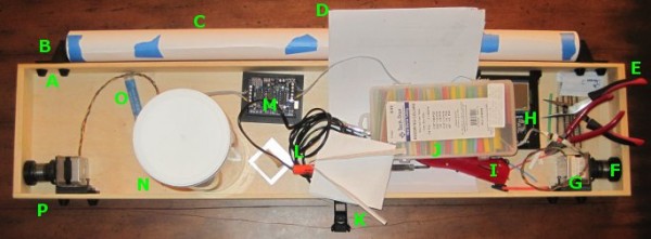
Above is a picture of my drawing robot, still a work in progress. The great thing about this particular project box is that it also doubles as a work area. It’s a good place to cut and strip wires, solder, assemble parts, and it’s totally portable. The box is 3′ long, 8″ high, 2″ inches deep.
A. Printed Bolt Covers. An M3 nut goes into the recess and the end of the bolt is covered by the printed part. One of these goes over every one of the protruding bolts in the project box.
B. Printed Paper Roll Mounts, on a Slide. These are actually three separate printed parts. Since the paper roll came without a cardboard tube, I put a wooden dowel down the center, with printed plastic caps on either side to hold the paper in place. There are two printed holders which the wooden dowel slot into. Each of the printed dowel holders slide left and right on a track and have a bolt that can be tightened to keep it from moving.
C. Paper Roll. After looking in a few craft stores I finally found a big long roll of paper at Staples of all places. I think it was marketed as paper you would use to cover a table. It’s thin paper, but there’s a lot of it and it was really cheap. With no internal cardboard tube, I had to design endcaps to keep it from wobbling all around.
D. Maker Faire Application. I’m hoping to display this robot at Maker Faire Bay Area 2013. Since the call for Makers hasn’t gone out yet I just downloaded the Maker Faire New York 2012 application and filled it out. Now when the call for Makers comes, I’ll be ready.
E. Wire Cutters and Pliers. These are just necessary tools. When I need something to hold tiny parts I wrap a rubber band around the pliers and they’re a tiny vise.
F. Printed Spools. Two printed plastic parts plus three nuts and bolts. Definitely overengineered, but they don’t have the weaknesses of a single print spool.
G. Motor Bolted to Motor Mount, on a Slide. The motors are bolted to a plastic mount with a groove. The motor mount is then slotted onto the slide which is itself bolted to the actual project box.
H. PolargraphSD in a Printed Case. I designed and printed the case. The way it is mounted to the project box, it is slightly offset from the box, which gives the circuit boards extra ventilation.
I. Stick Lighter. I used this stick lighter to heat the heat shrink.
J. Heat Shrink. Lots of heat shrink in varying colors and diameters.
M. Adafruit Motor Shield on an Arduino Uno, in a Printed Holder. Well, that about says it all. I would point out that the printed holder is pretty terrible – it’s just a little too small. The only reason I put the Arduino and shield in the box was so that I could hook up the motors and make sure everything was still in operating condition.
N. Big Container of Zip Ties. Zip ties are useful.
O. Solder. For soldering.
P. Monofilament Guide. You can’t see it, but there’s a little plastic tube that fits into a hole drilled through the wood project box. It’s much smoother than wood and works great.
I’ve taken a lot of detailed pictures of the various parts and how they go together, so that comes next.
Electronics. The electronics are the brain and heart of this project. There’s really only two parts that could not be found or scavenged – these parts being the Arduino and the Adafruit Motor Shield.
Adafruit. I’m going with Adafruit all the way. Great website, great blog, great service, and their tutorials are super comprehensive.
These were the exact items I bought. To date I still have never hooked up the servo motor to anything, but I hope to soon. I could probably have substituted these smaller cheaper motors and used a left over power supply from some random project, but I knew these parts worked for others and would probably work for me.
If you were really just had to build a similar robot for as cheaply as possible, you could probably pull a pair of steppers and possibly a servo from some old printers, copiers, and the like.
Project Box. I’m using a long thin pine box left over after a huge catering party platter order. Frankly, you could mount the parts on nearly anything – a 2×4 or a nice custom box – it’s entirely up to you. Heck, you could even screw these parts directly into a wall if you were feeling particularly adventurous.
Structural Parts. Besides these main components, it’s really really useful to have a 3D printer to manufacture all the parts necessary to make it all work. Motor mounts, spools, etc. If you had a laser cutter or a ton of quick-set plastic, you could probably fabricate perfectly serviceable parts. The parts I’ve designed are ideally suited for my own project, could be modified for your own project, or you could just design some parts from scratch.
Hardware. There are also all the little bits of hardware to hold everything together. I still have a ton of M3x16 bolts and M3 nuts left over from building a Cupcake CNC and Thing-O-Matic. Besides these M3x16 bolts and M3 nuts, I did use two screwhead M3x16 bolts to hold the Polargraph case in place and eight M3x8 bolts to attach the two motors to the mounts.
McMaster has a truly amazing website. Even if you want to build a drawing robot and have zero parts on hand, you could pick up all the hardware you need from them super-cheaply. Update: The only thing I don’t care for about their website is that they don’t have a way of getting an estimate on shipping. Among McMaster’s virtues is their amazingly responsive customer support. I just asked them for a shipping estimate on these parts and they got right back to me. You could pick up a set of 100 nuts, 100 M3x16 bolts, and 100 M3x8 bolts for about $6. This is an absolute bargain for way more nuts and bolts than you’ll ever need for this project.
Yesterday I spent six dollars on eight lousy M3x8 bolts. Had I simply waited for McMaster, I could have had 100 M3x8 bolts for only $4.84
Chances are if you really had to you could use whatever bits of hardware you can find lying around your place. I’ve seen examples of similar drawing robots using zip ties to hold the motors in place.
Electronic Bits. I still need to track down some rainbow colored ribbon cable and connectors. While I do actually have all the pieces of scrap around my home to finish the robot right now, I don’t want to do this half-way. I want to use a rainbow ribbon cable because (a) I need to extend the motor leads to reach the circuit board, (b) it would be very helpful to have each lead color coded separately, and (c) they’re really pretty. As for the wire connectors, all the other parts to my setup are very modular and it would be very nice to have the electronic connections just as modular. After searching around, I found that Sparkfun has all the little pieces I need to finish this project.
Sparkfun. I’ve never really bought anything from Sparkfun before – but people I trust have spoken highly of them. I say never “really” because I bought into the Makey Makey kickstarter and they used Sparkfun to fulfill their orders.
4″ of 4-pin jumper wire for $0.95. My plan is to simply cut this female/female ended connector in half, solder each half to one set of motor leads, and then use normal headers to connect to these.
I’m completely confident that you could pull plenty of wire out of old electronics. They always have a ton of wire and connectors inside.
I recently had a very unsatisfactory experience trying to source some parts locally, so I”ll be placing an order for some ribbon cable and jumper wires from Sparkfun.