OpenSCAD Shadow Boxes, Shadow Casting

This slideshow requires JavaScript.

A friend recently requested some less LLM-centric content.  I’ve often said this blog is largely a lab notebook for various ideas or build log.  It’s also merely a subset of the stuff swirling around in my brain than a dedication to any one topic.  In any case, this post is dedicated to Pete.

I saw the above 3D printed box on Instagram.  It looks like a wanted poster from the show “One Piece” of a character named Roronoa Zoro who carries three swords.  The box contains a small post in the very center which seems very out of place – until the lights are dimmed and the light under the tip of the post is activated, revealing the light is blocked by the irregular edges of the box and casts a shadow of the silhouette of a figure holding three swords.

I’ve seen other implementations of this stereographic projection technique, but this was easily the coolest.  The disparity between the size and shape of the box and shadow was almost startling.

My mind went wild with ideas upon seeing this box.  One of the first ideas I had related to some fan-made movie posters by Kevin Collert many years ago.1 Imagine a small projector / box of arbitrary shape that could project that kind of silhouette behind you?

Yeah, a Tony Stark cosplay is neat… but what if you had an inconspicuous stereographic projector on your back that threw up a huge Iron Man shadow behind you!?

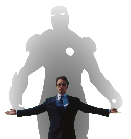
This could be extended in any number of ways.  A Luke Skywalker cosplay that casts a Darth Vader shadow, Bruce Banner with a Hulk, etc, etc.  But, also, what about a shadow of a familiar?  A little dragon perched behind you.  Or two thugs standing to your side like evil shadow henchmen?  Or a crowd of zombies?  The neat part about the box / lamp shown on Instagram was that the box didn’t look like it would display that kind shadow of a shadow.  It just looked like a box with weird edges to it.

But, how did they do it?

He makes a good point (iykyk)

I’m terrible at Blender.  I’ve watched tutorials, tried to use it, but I just can’t wrap my feeble mind around it.  My one string is the ability to make things in OpenSCAD.  There are plenty of others who can make incredible things in it, but I’m no slouch.  The code may not be pretty, but, well, as they say…

And, really, that’s all that counts

I started with a few assumptions.

  • The light source has to be a single point.  If there were multiple LED’s or filaments, it would create fuzzy / duplicate shadow edges.  This should be possible with a single bright LED.
  • The shadow is basically a cone.  The edge of the shadow everywhere must be essentially some sort of a distorted cone, with the center point being the single point of light and the edges of the silhouette being the edge of the cone.
  • The top edge of the box must be where the cone intersects with the box.  If we decide how far off the wall the point of light is and we know where we want the shadow to be and where the shadow edges are, we should be able to intersect the shadow-cone with a thin walled box.
A rough sketch of the idea

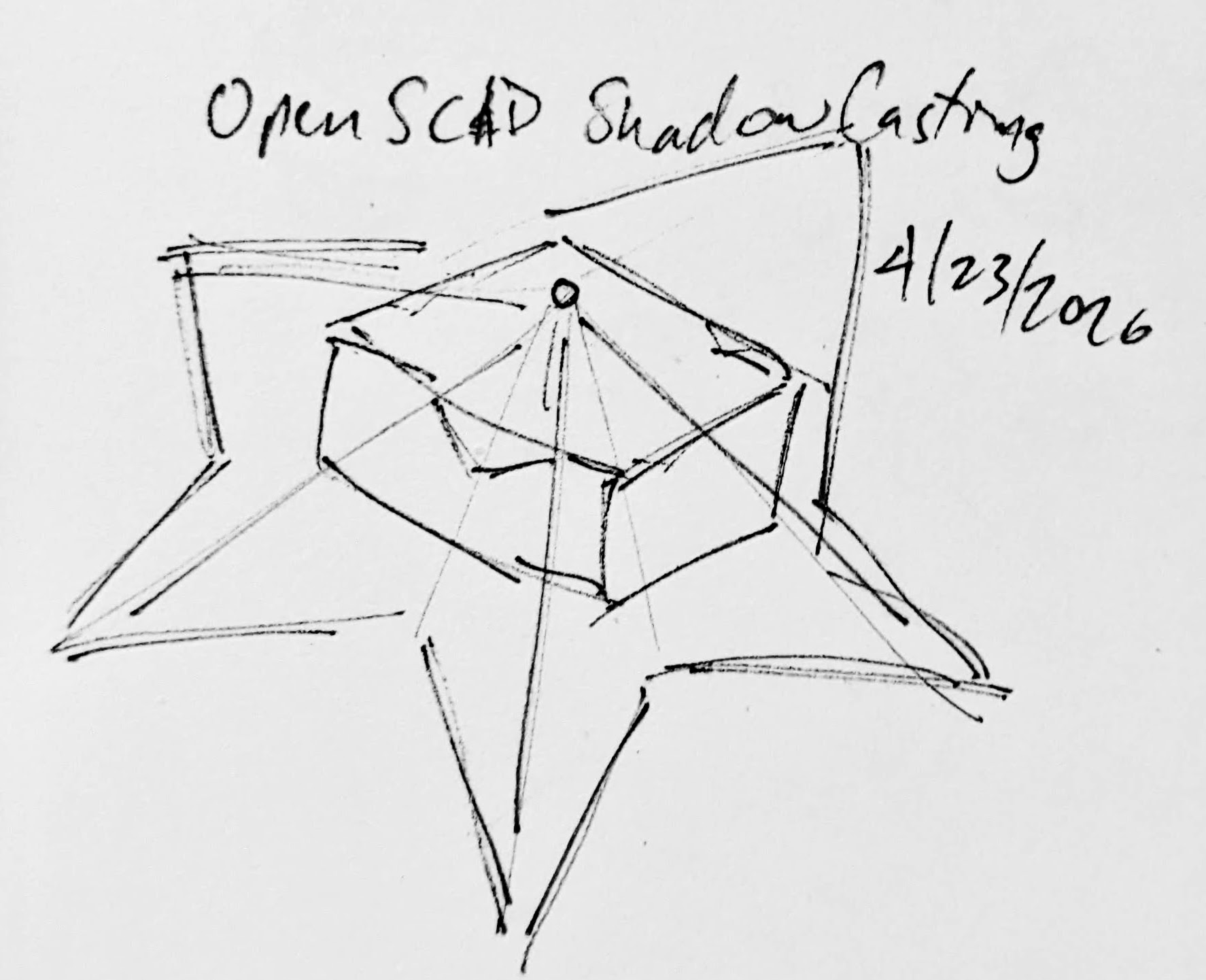
Creating the box itself shouldn’t be that big a deal.  It’s an easy few lines of OpenSCAD.  Creating the arbitrary “cone” was initially a much harder problem.  Now, if the design I was trying to create was very simple or entirely convex, I could just use the OpenSCAD hull function around an SVG of the desired shadow and a very small sphere for the point of light.  Since a simple shape would be uninteresting, I knew that hull wasn’t going to work.  For a while I tried really hard to build a python program that would work by creating a polyhedron built out of the large SVG in the desired location and a very small SVG at the light point – and stitching the sides together programmatically.  If you’ve ever worked with the OpenSCAD polyhedron functions, you know what a pain it is.  If you don’t define the faces in a certain order or order the faces properly, you’ll end up with flipped faces and a pile of useless triangles.  Even when the faces were properly built, the result ended up being difficult for OpenSCAD to render since it involved so many points converging on so few points and weird little overlaps.  It was a mess.

I’m listening…

You mean, all I have to do is RFTM?  Apparently the linear_extrude function has a parameter called “scale” where you can define how small something should get as it is extruded.  This is literally exactly what I needed.

I needed the shadow on the wall to be extruded off the wall as high as the point of light, but scaled down to that same point of light.  But, would this work???  I haven’t printed it yet, but I believe it should.

This slideshow requires JavaScript.

From there, the next question is… does this OpenSCAD back-of-the-napkin sketch really work?  Again, I’m not sure – I haven’t printed this for a few different reasons.  If this design were printed “as is”, there would be a ton of overhangs and support material.  I believe when you look at some of the pictures of the lamp lit up from the side, you can see the infill patterns on the sides.  I can’t tell from these videos – but I suspect the easiest way to 3D print this box would be to do so in big flat panels.  At the point you’re just trying to turn filament into 2D panels, why even bother printing it when you could lasercut it in a fraction of the time?

Let’s look at a few stills of the lamp.

This slideshow requires JavaScript.

Now, for my quick mockup I just used a simple square shape – but you can definitely see the same features as in the lamp in the video stills.  The head, the crossed sword tips at the left, the jagged edges on the bottom right, the floating sword on the right.

Common structural features circled

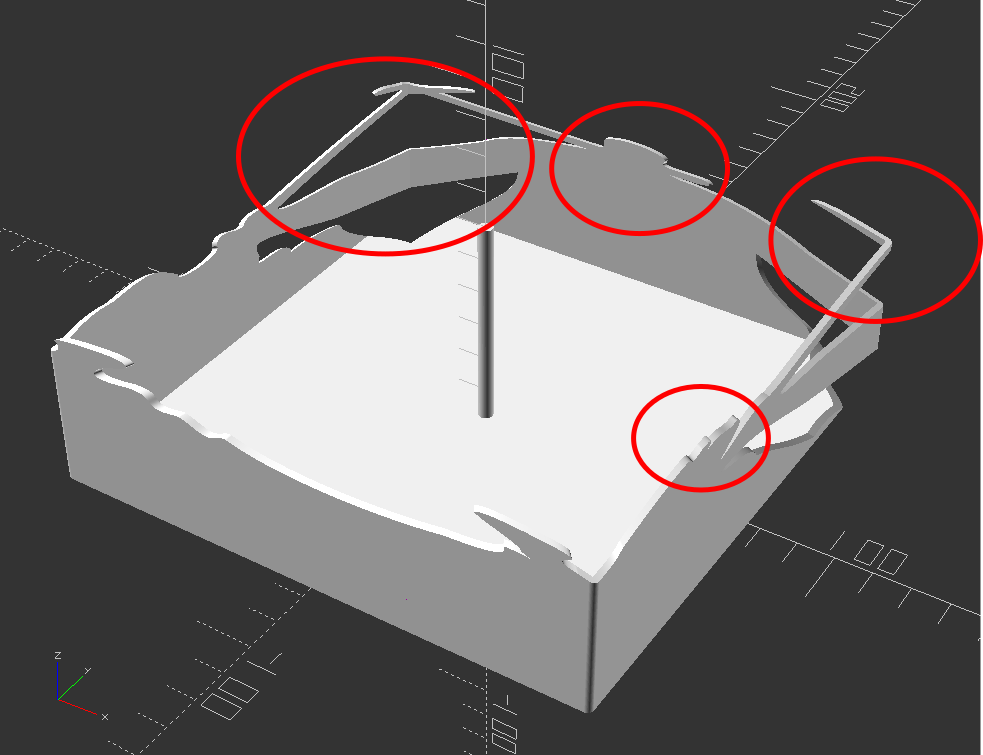
Given that the theory feels intuitive and sound and that my quick mockup proof of concept seems to have the same structural features as the lamp in the video… this seems like it would work.

If this quick mockup works, then why restrict ourselves to simple boxes?  For a mass produced thing you just want to stamp out, a simple box just makes sense.  You could lasercut the panels, slap them together, and churn them out all day long.  But, the thing that you use to block the light and form the shadow could be any arbitrary shape.  It could be a triangle, star, or something far more complex.  Here’s another quick sketch:

This slideshow requires JavaScript.

Obviously, this would be a support structure nightmare.  But, for a one-off project and a cool enough idea, I think it could definitely work!

  1. His work has been stolen and slapped on so many dropshipped things that it was very difficult to find the original artist! []

Inception and Exorcisms

Out!

I have found that if I have an idea, it will keep swirling around my brain unless I get it out in some way.  In a way, I’m exorcising myself to prevent these ideas from plaguing me further.  It’s not so bad having ideas pile up in my brain, it’s just that as long as they’re floating around, I’m not able to adequately devote sufficient brain cycles to other tasks.  I don’t know the reason for this – but my sense is that my brain will keep returning to these ideas, circulating and cycling them, because I don’t want to forget about them – and it can only truly relax once it knows the idea is somewhere it can’t be lost / forgotten.

A while back I had suggested the only good way I had to deal with these recirculating ideas was to either act on them (building / blogging) or killing them (organizing / bookmarking).  This wasn’t exactly true.

But, first, a digression.  Many years ago Bre Pettis and Kio Stark created a “cult of done” manifesto, a short set of ideas about how to consider things “done,” written in 20 minutes since that’s all the time they had to write it.  I think about this manifesto and this one particular poster implementation of it often.

James Provost’s Cult of Done Poster

I’m not sure what appeals to me so much about this manifesto.  I don’t know that I agree with each element – but for something generated in 20 minutes, it’s pretty good.  I guess the reason it comes back to my mind today, of all days, is that I happened to be looking back through my many blog posts with my eldest kiddo and was reminded of all the blogging I did here and at MakerBot.com and was reminded of those earlier, perhaps simpler and sillier, times.

Here’s how I actually exorcise / done-ify things:

  • Build the idea
  • Blog (and publish) the idea
  • Bookmark the page and sort that bookmark
  • Write the idea down in a note app
  • Write it down or sketch it in a notebook / sketchbook
  • Send the idea to someone

Sometimes I can accidentally let years go by without talking to a friend.  It’s not a good quality – but at least I’m able to recognize this personality trait.  My way of keeping in touch with people is that when I see something that reminds me of them, I’ll send it to them.  This isn’t so unusual … but sometimes I do this same thing with a slightly less pure motive.  Sometimes when I have an idea or see something interesting, I don’t just store it in a bookmark or by writing it down… I consciously make an effort to store it in a friend’s brain.

Yes, I’m sharing a thing with a friend as a way to connect, offer something to them that I know they’ll be interested in, perhaps to give us something to talk about, but I admit that I also consciously share it with them in order to further store the same data within their brain and in our communication channels.1 Again, not my finest quality, but it’s not an entirely selfish quality either.2  The hilarious thing about this last way to done-ify something is that you could even store the data in the brain of someone you hated!  Heck, you could rage-tweet it to someone.  And, the stronger your reaction to them, the stronger the connection you would have to the memory of the thing!

Taking all that into consideration, here’s how I probably actually exorcise / done-ify things:

  • Implement: Build the idea
  • Externalize:  Publish the idea
  • Memorialize:  Write down, bookmark, sketch,
  • Incept:  Store the idea in someone else’s brain
  1. Texting, messaging apps []
  2. Though, I suppose “not entirely selfish” isn’t exactly a resounding exoneration. []

[2025] Google Pixel Boot Loop Fixes

In the 7 years since I wrote a blog post about rescuing my Google Pixel from a boot loop people have started reaching out to me desperately looking for a way to fix their phones.  This particularly horrible glitch happens at the worst time – when your phone storage is completely full of pictures and videos.  In my case, we were on vacation and not near wifi when I’d happened to fill up the phone storage and it got stuck in a boot loop.1

Google Support was adamant there was no way to recover my data and my options were to factory wipe the phone myself or send it to them so they could do it.  Of the resources found back in 2018, almost nothing survived Google’s march of “progress” and destruction of their own older resources.  In this case the links to Google’s own Pixel support forums and links to resources no longer work – and there are no working Archive.org / Way Back Machine links.

Anyhow, if you’re stuck in the same situation as I was – without the resources and links I had back then, perhaps if you dig around you can still find a way?

“If you have a problem, if no one else can help, and if you can find them, maybe you can…”

Before you get started – a warning.  I don’t currently have this problem and am trying to piece together how I fixed my problem 7 years ago on an older phone, using current guides that are no longer accessible.  I haven’t verified any of these links and resources, I’m just some rando on the internet who is trying to help you out because some other internet randos helped me out a long time ago.  Google has a nasty habit of deleting their own resources and shuffling things around.  I don’t know the first thing about installing new operating systems on phones and following any of these links or suggestions might permanently damage your systems.  But, as I mentioned before…  I tried this because Google Support was beyond unhelpful and I was completely out of options.

You’ve been warned

The basic framework for the fix was:

  1. Get the phone to “Recovery Mode” so at least isn’t not boot looping, overheating, and chewing up your battery.
    1. If you have an unlocked phone, or a locked phone from Google which you could theoretically unlock over a terminal, you should be able to get the phone “Safe Mode” where it will be able to turn on and access the operating system, but with limited other apps useable.
  2. Find and install the latest Android ADB (Android Debug Bridge) and FastBoot (an Android diagnostic tool)
    1. I say “latest,” but I’m not an expert and am not currently having this problem.  Perhaps it’s best to use the version which most closely matches your phone?  Anyhow, I installed ADB on the root of my PC and then created a path to it with “SET PATH=%PATH%;c:\adb” so the operating system would know it could access those resources.
  3. Try to find a “Rescue OTA” (Android Rescue Over-the-Air update) for your phone model.
    1. This would essentially be the same update that you might get when you let your phone download and install an update over night via WiFi – with the only difference that you’ve downloaded it onto your PC and are going to try to shove it back into the phone over a cable.
  4. Try to “sideload” the OTA update back into the phone using ADB / Fastboot (I don’t remember the specific steps to do this – but since these resources are constantly being worked on, I assume someone has written a guide).

If this post helped you out or you found some resources helpful, please let me know so I can update this post and help others.

Good luck!

  1. It was also overheating – which might have been a contributing factor the boot loop – or caused by the constant booting and looping []

Capstan Drives as alternatives to Planetary Gears?

Sometimes I hate the algorithm and sometimes it shows me cool new robotics / mechanics / gadgets and makersAaed Musa has been working on something called a “Capstan Drive” which is a rope driven alternative to gears.  By removing gears and  teeth and replacing them with rope you cut down on noise, eliminate backlash, high torque, low inertia, and low cost – with the major costs being low range of movement and a vertical path for the rope to travel over.  Aaed’s video is well worth a watch and blog well worth reading.  But… if you want to get a sense of how the Capstan drive works…

Capstan drive in action

The benefit of a planetary gear is that it’s a very vertically compact method for increasing rotational speed at the cost of complexity.  With a Capstan Drive (I don’t know if this is supposed to be capitalized) the rope needs to be wrapped around the thinner shaft several times to prevent slippage.  As Aaed notes:

One question that I had when first exploring this reducer was “why doesn’t the rope slip if it’s just wrapped around the smaller drum?”. The answer to that question lies in the capstan equation. With each turn of rope on a drum, the amount of friction increases exponentially. With 3-5 turns of rope, there is enough friction for slipping to not be an issue.

Aaed indicated he was using Dyneema DM20 cord as it has almost no stretch to it.  I wonder if something like fishing line would work?

DIY Lightsaber Build
  1. TwistSabers
  2. DIY Lightsaber Thoughts
  3. Wait, haven’t I worked on this before?!
  4. Considering the design elements of a DIY light saber
  5. More Musings on Lightsabers, Mechanical Components
  6. Slow Progress…
  7. Capstan Drives as alternatives to Planetary Gears?

Fixing a coiled zipper that won’t close

I have a favorite soft pencil case made from faux leather that I’ve been using for more than 20 years, but the zipper had gotten finicky and started to not close.  It started having a problem zipping closed on just one side, but today it wouldn’t close at all and the slide was just moving back and forth without closing anything at all.

After a quick search, I found a video by UCAN Zipper USA with a solution that fixed it immediately.  The narrator said the problem was the zipper started to “open a little bit” with repeated use.  I suspect the slider on my pencil case opened a little by vigorous use or sometimes by accidentally zipping it over something that had been caught in the zipper teeth.

The solution was quite simple:

  • Inspect the closing side of the zipper to see whether one side is more “open” or riding higher than the other.
  • Using pliers, gently clamp that side down just a little, then try to open/close the zipper.  If it doesn’t quite engage yet, clamp down a little more.
Gently clamp the rear / closing side of the zipper where it appears to be loose / open / ride higher

That’s it!  It worked like a charm for me.  While this worked for a coiled zipper, I suspect it would also work for a molded tooth zipper as well.

Slow Progress…

… is still progress.

I designed a planetary gear assembly, more to see whether parts this small would even turn out than to actually make a working component.  The gears are about 3 mm thick, but half of that is the larger part.  I forgot that you can’t have a two-level gear mesh against another identical gear, so these didn’t move at all.

A test planetary gear assembly

I reprinted the parts, this time increasing the center hole size and also removing the teeth off the larger side.  It kinda works, but it’s very finnicky.  This might be a side effect of these gears being very thin and the teeth very small.  I think it’s probably worth sacrificing gear ratio in favor of larger, more consistent teeth.

Small improvements

The OpenSCAD code is a mess, lots of vestigial code remains, lots of non-working parts are commented out, and it all just needs more comments in general.  I hate looking at it.  But, as one of my favorite memes goes…

I mean, he’s got a point
DIY Lightsaber Build
  1. TwistSabers
  2. DIY Lightsaber Thoughts
  3. Wait, haven’t I worked on this before?!
  4. Considering the design elements of a DIY light saber
  5. More Musings on Lightsabers, Mechanical Components
  6. Slow Progress…
  7. Capstan Drives as alternatives to Planetary Gears?

Thermal QR Code Sticker Success!

I could not be happier with how this little thermal label printer turned out!  The highest use case I had for it was to create small QR codes I could stick in my various maker notebooks so that I could easily connect specific pages in my notebooks back to blog posts, essentially being able to embed unlimited digital resources into a simple page.

This slideshow requires JavaScript.

Basically, I arranged the QR codes and text in Inkscape, exported to a flat JPG, saved to my phone, and then printed.

The failed prints you see were printed at Dense, Medium, and then Light, but all came out useless. I realized it was because I had exported the image at 72 DPI, which meant that once the image was exported to either PNG or JPG, the image had gray aliasing between what should have been sharp black and white edges.  This caused the printer to treat the grays as black, which meant the black areas were obscuring the lighter areas, making it harder to scan the images.

I exported at 900 DPI and it printed on “Light” flawlessly. Each QR code sticker is only 12.5mm square, I can fit 8 of them per sticker sheet, and each includes a short label, and can be read by my phone very easily.  Now, I don’t think a 900 DPI image is required to print fine details, but I figured why the hell not give it a shot?

The first website QR code generator I tried was actually a sneaky website.  Rather than creating a QR code for the destination, it ran the URL’s through their own URL shortener, then output that QR code.  I chose that generator since it permits you to select the desired error correction level, but the result was basically useless to me.  If I wanted a QR code pointing to a short-code, I would have pointed it at my own short URL service.  While an unshortened URL will create a larger or more dense QR code, it has the benefit of being somewhat transparent.  When you scan an unshortened URL, your scanning app can show you the destination that would be hidden by a URL shortener.  I ended up using this website to generate the QR codes which allows you to specify the URL, choose from various error correction levels, and then download in a variety of formats.

I was able to pack detailed, unshortened, URLs into just 12.5 mm square plus 4.5 point font labels.  I might be able to print smaller than this, but I don’t have any pressing need to do that.  I’ve seen some suggestions a QR code should be printed at least 10mm square, and this is just above that limit.  However, I suspect those guidelines are for commercial use, whereas these codes are likely to be rarely scanned and don’t need to be optimized for widespread use – just for my own personal benefit.

Thermal Sticker Printer
  1. QR Codes and Avatars
  2. Sticker Printer
  3. Thermal QR Code Sticker Success!

Prelude to Protractors

I was flipping through my smaller notebook and remembered I’d already posted about a credit card sized design for a protractor and ruler.  I decided to connect this to my recent other design and turn it into a short series.  This design predates the one I most recently made and shared on this site, thus the title.

While I posted a writeup to Instagram, for some reason I didn’t put anything here?!  Other websites go away over time and even if mine doesn’t last forever, well, at least it’s still mine.  Thus, here’s the photos:

This slideshow requires JavaScript.

And, just in case1 Instagram completely evaporates, here’s the writeup I posted:

A DIY protractor / ruler / template card.

I needed a quick and convenient way to make straight (ish) lines and angles that I could keep in my small notebook.

The little card is about the size of a playing card and acts like a 5mm increment ruler, 10 degree protractor, and can make it easy to draw a grid.

This all started because I was working on an electronics project, needed some resistors and haven’t memorized the color chart, decided to draw a color chart in my notebook, needed a grid / ruler, decided to design my own after seeing a neat metal one on Kickstarter.

OpenSCAD -> Inkscape -> Print -> tape to card -> craft knife -> drawing

Now I have a little template measuring tool that will let me draw circles, angles, lines, grids, and dots. I’m very happy with this. :)

I may try to lasercut one from a thin sheet of plastic

Enjoy!

Small Rulers and Protractors
  1. Inkscape Protractor and Rulers
  2. Prelude to Protractors
  1. God willing []

More Musings on Lightsabers, Mechanical Components

Other Lightsabers

After doing so many web / Youtube searches and watching so many videos on the topic of lightsabers, the algorithm quickly caught up to me and started showing me similar things.  There was one excellent video by Cleo Abram going behind the scenes at Disney to talk about how their incredible designer / engineer / imagineer Lanny Smoot invented a realistic looking lightsaber.  Another excellent video was by HeroTech going over his designs for building a DIY lightsaber with sounds, swift extension, and retraction.

This slideshow requires JavaScript.

Lightsaber Dimensions

There are now so many entirely “cannon” lightsabers out there that there’s no way to know what the “real” dimensions of a lightsaber should be.  Yoda and the younglings from Revenge of the Sith likely had shorter, thinner lightsabers, Kylo Ren probably had the chonkiest, Darth Maul had the longest, etc.  I think it probably comes down to what’s the most satisfying for the user to hold.  When it comes to a DIY lightsaber where the blade is stored inside the hilt, the blade length is going to be the number of segments multiplied by the difference of the hilt length and any overlap necessary to keep the segments steady.  If we’re going with three blade segments, we can then work backwards from what would be a comfortable grip size to determine what we can fit into the hilt.

From the TwistSaber kickstarter videos, I would guesstimate the diameter of the hilt is around 2″ or 50mm.  TwistSaber core slots into their hilts, so the entire mechanism of planetary gear, screw core, and blade slides must all be thinner than the inner diameter of the hilt.

Planetary Gears

It took me an embarrassingly long time to play with the MCAD library to produce involute gears.  Once I was able to generate gears, I was banging my head against the idea of how to create properly meshing gears – that is, until Pete Wildsmith swooped in with the assist.  He pointed me in the direction of Mattias Wandel’s excellent page on the topic of meshing gears.  What I learned were these items:

  1. There is a very specific relationship to make a planetary gear where the planet gears are evenly spaced and mesh properly with both the sun and ring gears.  The number of teeth in the sun gear must be an integer multiple of the number of planet gears.  And, in turn, the number of teeth in the ring gear must be an integer multiple of the number of teeth in the sun gear.
    1. To increase the gear ratio from ring to sun gear, I needed to minimize the sun gear teeth and maximize the ring gear teeth, this meant the number of planet gears had to be minimized to keep the number of sun teeth down.  However, I liked the idea of three planet teeth basically surrounding the sun gear, keeping it aligned.  Thus, I arrived at a constant for the number of planet gears; three.  From here, the choice is whether to give the sun gear a multiple of 2 or 3 of the number of planet gears.  I chose a multiple of 3 because having only 6 teeth looked fairly weak and I didn’t like the idea of putting so much pressure on those teeth.  Thus, the sun gear has 9 teeth.  In order to get sufficient rotations of the sun gear from a half rotation of the ring gear, I chose a multiplier of 7 for the ring gear.
    2. Thus, we have 3 planet gears, a sun gear with 9 teeth, and ring gear with 63 teeth.
  2. The number of meshing teeth to a planet gear in the above setup is derived by subtracting the sun gear teeth from the ring gear teeth, and dividing this by two.
    1. In our instance, it would be (63 – 9)/2 = 27 teeth
  3. I learned the hard way, through trial and error, that apparently all meshing gears required the same “circular_pitch.”
    1. All this seems to do is scale the entire gear up or down in size.  Fortunately, I don’t have to understand how the library works in order to wield it’s magic.  I just fiddled with the circular pitch until the set of gears were the approximate size I needed.
  4. When orienting the gears together, I wasn’t sure how far to place the planet gear from the sun gear.  Luckily, Matthias provides this answer.  The offset of the planetary gear is calculated as (circular_pitch / π) * (Sun Teeth + Planet Teeth) / 2

Design

When I design certain mechanisms, I like to try and design the components in the smallest and most extreme ways – so the OpenSCAD designs can be modified to build something larger and less extreme.  By “most extreme ways,” I mean the design gets tested for very thin parts, very steep or low angles.  The plan is that if I could design very thin shorter parts and they appear to work, I could print them quickly to test them, iterate, and then try them at full scale.  This is why I have some half-baked cryptex designs that are absurdly small – they were designed intended to be parametric. 1

After a long and interesting search I couldn’t find the goggle components pictured in a prior post, and decided to just buckle down, tinker with some old designs on spiral telescoping parts, scale them to fit in the goggles, and start printing a new set.  Of course, as anyone knows, there is no surer way to summon a lost object than to order/manufacture a new one.  Maybe 30 minutes into the print job, I discovered the goggles printed in copper plastic sitting on a shelf.

This slideshow requires JavaScript.

It was an interesting search because I found bags of prototypes of other projects, including some thin segments of spiral telescoping parts, which gave me something to play with and be inspired by while I tinkered.

I’d like to put these designs to work building a working telescoping, planetary gear operated, set of goggles.  Who knows?  If I stuck a lens in them, perhaps a Frensel lens, they might even work as a magnifying device.  And, if not, I’ll probably try to find a way to shoehorn some LED’s into them.

One other thing that’s been eating at me.  There are essentially four blade segments.  These are the three we see throughout construction videos, plus the casing which the outermost blade segment slides along.  There are very few videos of the entire assembly working with a cutout view, but there are definitely only three actual spiral core pieces.  And, yet, when the blade is extended, we can see the tip of the blade extend out further than the outermost spiral core piece.  This means, from the hilt to the top the lightsaber is one hilt plus three blade segments long. 2  Then there’s the three central spiral cores, but if they’re fully extended and the center blade segment extends beyond the spiral core… how?

Although I haven’t seen any part of the schematics or operation to demonstrate this, I think the central blade segment might have a spiral section within it.  Unrelatedly… does this mean that all the blade and spiral segments could possibly be printed in place at the very same time?

Can LED’s be fit into an extending lightsaber?

One of my all time favorite Simpson’s clips where Skinner’s mother berates a grocery store clerk, “I want everything in one bag… and I don’t want the bag to be heavy!”

It’s certainly possible to make a realistic looking lightsaber, but it’s not likely to be sturdy enough for performance / battles.  Cleo’s video has Mr. Smoot looking mighty apprehensive that she might attempt to more than very gently gesture with the lightsaber.  You could make a lightsaber that has great sounds, great blade, great lights, but the blade won’t retract.  You could make a super dangerous plasma lightsaber capable of cutting things… with 4,000 degrees Fahrenheit, but it sure won’t be portable.

I do wonder whether it would be possible to add lights to this kind of a lightsaber.  I think it might work if there was a ring LED around the planetary gear / base of the central spiral core.  Perhaps LED’s could be placed along the inside of the blade segments, but I’m not sure how you’d route power to these things as they slid along.  Perhaps through the use of copper tape or conductive maker tape.  I think these are doable, but would require a lot of testing, calibration, and probably thicker blade segments or very thin LED’s.

DIY Lightsaber Build
  1. TwistSabers
  2. DIY Lightsaber Thoughts
  3. Wait, haven’t I worked on this before?!
  4. Considering the design elements of a DIY light saber
  5. More Musings on Lightsabers, Mechanical Components
  6. Slow Progress…
  7. Capstan Drives as alternatives to Planetary Gears?
  1. I created a working prototype, it’s about half the size of a roll of lifesavers, and then got distracted by something.  While I’d like them to be parametric, and perhaps they are, I have a feeling some odd choices in there would prevent it from being truly parametric in the way much better designer/programmers are able to accomplish []
  2. Setting aside overlap, etc []

Considering the design elements of a DIY light saber

I like to think about projects in discrete parts, trying to solve one part, then moving onto another section.  In the case of this DIY lightsaber build, I’ve been burning some brain cells thinking about this project.  Just by looking at the publicly available images of the TwistSaber, what can I infer about it’s construction?

Planetary Gears

TwistSaber Gears

I would guesstimate the gears are probably about 8 mm in height.  When I want to make a very sturdy part, I’ll use a 3 mm thickness.  However, these gears look extra chonky, so let’s go crazy.  Making further, and more in depth, guesses…  Let’s see what happens when we toss the above image into Inkscape and try to lay some star shaped polygons on it.

This slideshow requires JavaScript.

I would estimate the ring gear has 58 teeth, the planetary gears appear to have 20 teeth, and the sun gear to have 10 teeth.  When you’re dealing with printing with tight tolerances and thick (0.4 mm) extrusions, you can’t make the teeth too small, but you need enough teeth so permit smooth operation.  In any case, we can count on some sweet OpenSCAD gear library magic to help us design these planetary gears.

Screw Threads

Since we’re already talking about the planetary gears, let’s think about the spiral core rotations and screw thread.  If the 58 tooth ring gear goes through a half rotation, it will rotate the 20 tooth planetary gears by 26 teeth, causing just over 2 rotations of the 10 tooth central sun gear.  The math should math like this:

  • ((ringTeeth / planetaryTeeth)) * (0.5 rotations) * (planetaryTeeth / sunTeeth) =
  • (58 / 20) * 0.5 * (20 / 10) =
  • (58 / 20) * 0.5 * (20 / 10) =
  • 58 * 0.5  / 10 =
  • 29 / 10 = 2.9

This tells us the half turn of the hilt should cause nearly 3 turns of the central spiral core.  If we had a zero degree spiral around the central core, the screw thread would not be a spiral but rather a straight vertical line.  If we had an absolutely crazy spiral, like a million degrees of turn, the screw thread would be nearly horizontal.  We’re going to need a slope for the screw thread that causes 2.9 revolutions over 200 mm.

Screw Core

The three central screw segments have some interesting design elements.

This slideshow requires JavaScript.

By tracing the image of the screw threads, in alternating yellow and red, we can see the path of the screw threads on the camera facing side of the tube.  However, by duplicating these tracing and flipping them along a horizontal axis, we can see this means there’s just two screw threads.  In an earlier post I had wondered at the optimal number of screw threads.  You want sufficient separate threads to work to actuate the core evenly, but not so many that they introduce unnecessary friction.

We already know from various videos and GIFs the screw core is attached to the hilt at the thinnest of the three segments.  It’s interesting then that the two larger tubes have flared ends with rounded notches on one side.  Although I don’t have a photo or still frame to show this, I suspect these are meant to lock against the base of the blades.  My working theory is you insert the core into the nested blade segments, and then pull them back so they click into the base of the blades.

Here’s my thinking…  let’s assume the spiral core pieces do not connect to the blades segments at all – except at the very bottom and very top.  When you rotate the spiral core center, the other two core segments could extend – but might do so unevenly based upon how much friction there might be between any two adjacent parts.  If the spiral core pieces do connect to the blade segments, then each of the three blade segments should actuate at the same rate (rather than whichever one has the least friction).

I need to give this more thought – I have an idea, which if correct might be a simpler way to design this mechanism for 3D printing.  (It would be probably impossible for injection molding though…

Blade Segments

The blade segments are interesting in their own right.  There’s no clear picture of how many rails exist within these blade parts.  However, we might be able to extrapolate this from the portions we can see.  In the second of these two screen shots, you can see two and a half sets of rail alignment nubs.  If there is an equal number on the reverse, then perhaps there are five alignment rails inside each blade?

This slideshow requires JavaScript.

One nice thing about OpenSCAD is the use of parameters.  There’s no reason I couldn’t design a similar device, but specify the blade segments should only be 20 mm tall, and then print out an incredibly stubby light saber.  If the mechanism work, then I could just adjust the blade segment height from 20 mm to 250 mm and try printing it again.

DIY Lightsaber Build
  1. TwistSabers
  2. DIY Lightsaber Thoughts
  3. Wait, haven’t I worked on this before?!
  4. Considering the design elements of a DIY light saber
  5. More Musings on Lightsabers, Mechanical Components
  6. Slow Progress…
  7. Capstan Drives as alternatives to Planetary Gears?