Design-print fail

I’ve been slowly working on the design of a printable (and fully MakerBottable) sonic screwdriver.  This model of the sonic screwdriver is built up of a number of concentric cylinders, has several significant overhangs well in excess of 45 degrees, and is larger than the MakerBot’s built capacity.  In order to deal with these design problems, I modeled it in sections.

In order to make the overall result something I could just pop/snap/slide together I designed it making some sections which were split vertically and other sections which slide around those sections to keep them together.  In order to make the parts quickly printable I designed all the parts at around 0.5mm thickness.

About 40% of the way through the print one of the vertical sections wasn’t coming out properly – probably because it was too thin.  The parts were too thin and flexible and ended up tearing between layers and just being too flimsy.

I also noticed something odd – the extrusion was too thin on that side of the model.   I can’t be sure why this is happening – but I suspect it’s due to the extruder not getting a good enough grip.  Perhaps I need to floss the extruder pulley or install a new extruder idler wheel.  However, it doesn’t explain why the extrusion was too thin on just that one side and no other spots.

Suggestions?

Hareware isn’t everything

With Charles Pax’s recent proof-of-concept of a motorized conveyor belt print platform, we’re going to need some software/firmware changes to make full use of these improvements:

  1. Queuing print tasks
  2. Removal/auto-wiping of the test extrusion
  3. Moving the print platform to the front/back/side of the MakerBot for ejecting the finished print
  4. Ejecting the printed part
  5. Returning the platform to 0,0,0 / center

From the video posted on Charles’ site, it looks like he’s managed #3 and #4 already.  The extrusion path around the print that we see in Nophead’s prints probably would work at #2.  I also seem to recall some (such as Zaggo?) have mounted a toothbrush head on the build platform for auto-wiping of the extruder head.

Returning the platform to 0,0,0 is an interesting proposition.  This would seem to work best once the opto-endstops are installed.  I’ve got my set of six fully assembled opto-endstops sitting in a box next to my MakerBot because I haven’t really needed them and they tend to get in the way of printing.  Although the opto-endstops have been removed from the standard MakerBot kits, I think we may now start to see them returning.

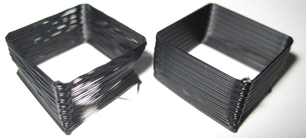
Skeinforge calibration test 1, 2

Test 1, Test 2

Test 1, Test 2

For these tests I used the “single walled test piece” from Da3v

  1. Test 1 on the left
    1. Temperature: 220
    2. Skeinforge -> Carve -> Layer Thickness (mm): 0.36
    3. Skeinforge -> Speed -> Flowrate PWM Setting (if PWM Setting is Chosen): 230
    4. Skeinforge -> Speed -> Feedrate (mm/s): 40
    5. Skeinforge -> Speed -> Travel Feedrate (mm/s): 40
    6. Extrusion diameter: 0.57
    7. Skeinforge -> Speed -> Extrusion Diameter Over Thickness (ratio): 1.583
    8. Wall thickness of the test piece: 0.40
  2. Test 2 on the right
    1. Skeinforge -> Speed -> Feedrate (mm/s): 30
    2. Skeinforge -> Speed -> Travel Feedrate (mm/s): 30
    3. Wall thickness of the test piece: 0.40
    4. Skeinforge -> Speed -> Extrusion Diameter Over Thickness (ratio): 1.583
    5. Skeinforge -> Carve -> Extrusion Width over Thickness (ratio): 1.583
    6. Skeinforge -> Inset -> Extrusion Perimeter Width over Thickness (ratio): 1.583

That’s a pretty big improvement.  I haven’t tried printing something small with lots of details, but now I’m curious how well these settings hold up.  My previous settings (which I zipped in case I totally messed this up) were reasonably good, but the layer adhesion was merely adequate.

How to caliberate and tune Skeinforge for your MakerBot

Update 4/21/2011: This post is more than a year old.  Since then I’ve created ProfileMaker which should eliminate the need for almost all of these steps.  Share and enjoy!


A MakerBot Operators group member, Cliff Biffle, has posted a very comprehensive list his Skeinforge tuning and calibration procedure.  Cliff owns MakerBot #69 from Batch#4, named Kallisti.  Although Cliff has a MakerBot Skeinforge tuning page, it looks like he hasn’t had a chance to transcribe his lab notebook yet.  However, Cliff has been patient enough to type up his Skeinforge calibration information twice for the benefit of the MakerBot Operators group.  Here are links to his original postings on 1/6/2010 and another on 1/15/2010.

The other day I wanted to go back and find his calibration procedure, but had forgotten who had posted it, when it was posted, and which thread it was posted.  Having now found it, I don’t want to lose it again.  It turns out that Cliff had posted it once in response to my own question about dialing in Skeinforge settings in order to print up lego pieces!  Thanks Cliff!

I’ve mashed his two posts together to put together this checklist:

  1. Adjust Temperature:  Skeinforge -> Raft
    1. Find a temperature that allows you to extrude quickly and easily without too much popping or smoking
    2. MakerBlock: I have one of the 1mm thermistors, use the Zach 1 temperature table, and print reliably at 220
  2. Adjust Layer Height: Skeinforge -> Carve -> Layer Thickness (mm)
    1. Cliff uses the default of 0.36
  3. Adjust Extrusion Speed: Skeinforge -> Speed -> Flowrate PWM Setting (if PWM Setting is Chosen)
    1. Make the extruder go slower and lower the PWM value
    2. Cliff uses 230
  4. Adjust Feedrate: Skeinforge -> Speed -> Feedrate (mm/s)
    1. Too fast and you lose the fine detail and introduce errors.  Too slow and it will be too… slow.
  5. Adjust Skeinforge to understand how much plastic is being extruded
    1. Raise the Z axis and perform a test extrusion into the air
    2. Do not pull or stretch the extrusion
    3. Using calipers, measure its diameter, D
    4. Go into Skeinforge and look up the configured layer thickness, T, from Skeinforge -> Carve -> Layer Thickness (mm)
    5. Divide the diameter by the thickness, D/T
    6. Set Skeinforge -> Speed -> Extrusion Diameter Over Thickness (ratio) to D/T
    7. Print a test piece with thin walls
    8. Measure the width, W, of a single extrusion somewhere above the first few layers
    9. Divide the width by the thickness, W/T
    10. Set Skeinforge -> Carve -> Extrusion Width Over Thickness (ratio) to W/T
      • Cliff said this setting may be in Fill, but I think he may have meant Carve

    11. Nick Ames has suggested setting Skeinforge -> Carve –> Extrusion Width over Thickness (ratio), Skeinforge -> Inset -> Extrusion Perimeter Width over Thickness (ratio), and Skeinforge -> Speed -> Extrusion Diameter over Thickness (ratio) all to the same value.  His post also has a lot of information and links about other potential Skeinforge tuning resources.
  6. Adjust other Skeinforge settings
    1. Overlap of grid corners
    2. Infill density
    3. Unpause
    4. Stretch