MakerBot starter kit

A little while ago someone posted on the MakerBot Operators group that they were looking for printed pulleys.  Apparently he had managed to scavenge or hack together everything else.

This got me wondering – what printed parts would someone need to get a MakerBot rolling?  There’s the obvious printed pulleys.  If I had a friend who was putting one together, I’d probably want to give them a spare insulator retainer ring and Z axis pulley.  What else should be in a MakerBot starter/welcome kit?

Differences between MakerBot Batch 9 and 10

Someone recently posted on the MakerBot operators group that there were some minor steps missing on the MakerBot Batch 10 instructions.  Just so you know the three things that person pointed out were fixed almost immediately.  You’re NEVER going to get that kind of service from IKEA.

In any case, this gave me the idea of perusing the Batch 10 instructions to see how they differ from my Batch 9 ‘bot.  Here’s what I’ve noticed:

  1. Different build order.  The Batch 9 ‘bot instructions show the body being built first, then the XY stage, then the plastruder.  Batch 10 shows the XY stage, then body, then plastruder.  I think you could probably build the Batch 9 ‘bot in the Batch 10 order without a problem.
  2. Different Y stage caps.  Batch 10 ‘bots appear to be using an Y stage cap that has more room for the pulley that rides on the Y stage.  My guess is that this will probably buy you a few precious millimeters of print space.  (The pictures say X stage end caps…  but it looks like the Y stage to me.)
  3. Different Y stage pulley.  Unlike my batch 9 bot, these instructions show assembly with a manufactured toothed idler pulley.  I have no idea what benefit is conferred by having teeth on that pulley.  Perhaps it is less prone to slipping on the belt?  Perhaps it makes it easier to tension the Y pulley without disassembling the Y stage?
  4. Different X axis pulley.  This manufactured toothed idler pulley looks similar to the one on the Y stage.

Why the toothed idler pulleys?

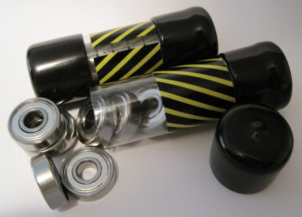
Ball bearings

A standard MakerBot Cupcake CNC requires:

  • 8x 608 bearings for the four X axis threaded rods
  • 2x 608 bearings for the two Z axis pulleys
  • 1x 608 bearing for the X axis pulley
  • 1x 606 bearing for the Y axis pulley

With all the cool things that could be built with the addition of bearings to a MakerBot toolkit I wanted to pick up some additional bearings.  I figure I could print an improved version of my retractable spring loaded tape measure, the microlathe, and other cool things.

But, where to find these things?  My local hardware store didn’t carry them.  I went to a hobby shop nearby which had exactly two bearings for $5.  It sounded expensive, but I’d never priced bearings before and I really just wanted the two at the time.

A few weeks later I had a brainstorm.  Where could I find cheap skate ball bearings?  Well, why not a place that sells cheap skates!  I called my local used sporting goods store and they had a 16 pack of bearings for $5.  Right on.

Ball bearings

Ball bearings

Pulley troubles

My MakerBot (Batch 9) uses printed pulleys.  I had attached them to my MakerBot with the bolt going down into the body with a nut underneath.  As far as I can tell, there’s only two ways to attach the printed pulleys to a ‘bot:

  1. Bolt going down into the ‘bot, nut underneath and inside, pulley with the tapered edge on the top.
  2. Bolt going up from underneath and inside the ‘bot, nut on top, pulley with the tapered edge on the bottom.
Printed pulleys, tapered end down

Printed pulleys, tapered end down

The problem with this orientation is that the pulley can slip down on the bolt.  When this happens it’s very easy for the belt to gradually ride up the tapered edge and then right off the pulley.  This ended up killing one of my test prints as the Z-stage started to descend to start the print.  Because of the way the “tapered end up” orientation of the pulley rides on the belt, I don’t think sanding away the taper would totally remove the problem.

One step forward, two steps back

As I mentioned, I had installed the Z-axis threaded rods without actually cleaning them first.  It wasn’t that bad to undo the caps, pull them out, and clean them.  In fact, it was kinda fun.

The process involves covering one end of the threaded rod with electrical tape to protect the threads and your drill, inserting that end into an electrical drill, adding 3-in-1 oil to the rod, and running the drill while holding a paper towel to the threads with a thumbnail.  It worked great and went much easier than I thought it would be.  I also used this opportunity to lower the threaded rods into the lower section of the MakerBot.  I’ll need to make sure they don’t get caught on any wires, but that will be all part of the process of zip tying all of the wires down anyhow.

Since I was going over things I had already done, I went ahead and also tightened up the Y-axis pulley.  It’s kind of a pain to adjust once the XY stage is installed, but I happen to have a very small adjustable wrench that was able to reach underneath the XY stage.

Shopping list

I’ll need a few extra things to get going:

  • Superglue for the idler pulley and bearing
  • 3-in-1 oil for the rods (I need to clean the threaded rods).  It will be a little bit of a pain to pull them out of the MakerBot, but I want to make sure I’ve done everything I can to make the robot work properly.
  • Popsicle sticks
  • Daft Punk

Building a robot that builds things

Once the painted parts were dry, I couldn’t resist getting started bolting the thing together.  Putting the parts together is pretty fun – it goes quickly and all the parts fit together very well.  In fact, it went so quickly that I didn’t get pictures of each step as I was originally planning.  Oh well, I guess you’ll just have to build one for yourself.  ;)

Behold!  A robot being born!
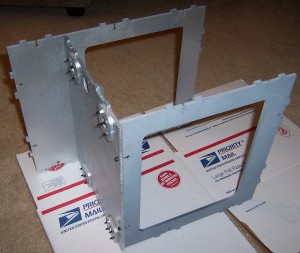
Front, middle, back, and Z-axis brackets bolted on

Front, middle, back, and Z-axis brackets bolted on

And now…
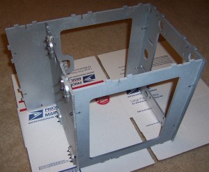
The top

The top

Here the body panels are mostly all put together.  You’ll notice I opted to install the Z-axis threaded rods after assembling the body.
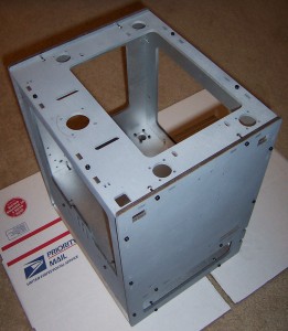
Sides, top, bottom all bolted together

Sides, top, bottom all bolted together

The new system is really huge improvement over the prior.  Before you had to get all of the Z-axis rods identically assembled and installed.  Now I just had to set them up, drop them in, make sure the top of the topmost pulley on each rod was just below the level of the top panel.  Any higher and it would have interfered with the smooth rotation of that axis.
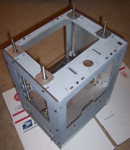
Z-axis installed

Z-axis installed

The Z-stage is also a huge improvement over prior designs.  Since the new brackets are “U” shaped, you can remove the entire stage without having to unbolt the entire assembly.  It’s also possible to adjust one or more rods individually by lifting the stage on that side slightly and rotating the hex nut as required.

I feel smarter just having seen these designs in action.

Second Law, Schmecond Law

Unfortunately, in the haste to get the MakerBots out the door for the holidays the guys at MakerBot left out opto-endstop kits on some shipments.  These guys have been super responsive even before I bought a kit from them, so I’m not that concerned.  Frankly, it’s a little bit of a relief that I can skip the soldering stuff for now and move on to some of the pulley making steps.

In any case, as I understand it, these are not vital to the proper functioning of the MakerBot and that they’re really just a failsafe if the ‘bot forgets the second law of robotics.