Whistles have been a staple on Thingiverse for years, probably because they’re such a small, simple, and impactful way to demonstrate the usefulness of a 3D printer. 1 I don’t know how many there are, but there are a LOT of whistles on Thingiverse. I’ve been curious about which whistles on Thingiverse are the loudest and conducted a semi-scientific experiment to figure this out.
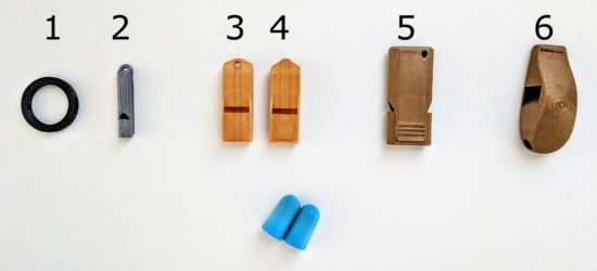
Six whistles
I say “semi-scientific” because I don’t have a decibel meter.2 My methodology was to have my family at one end of the house while I went to the other side, closed the door, put in my earplugs, and wailed away on six whistles as hard as I could. In any case, here’s my findings:
Name
Thingiverse ID
Mass (grams)
Price
Print Time (minutes)
Rank
Decibels
Extremely loud and compact emergency whistle [v1]
2933021
3.9
$0.12
22
1
TBD
2 chamber whistle (LOUD) [w5]
2616512
8.1
$0.24
49
2
TBD
Extremely loud and compact emergency whistle [v2]
2933021
3.7
$0.11
18
3
TBD
v29 (Over 118 db!)
1179160
13.9
$0.42
90
4
TBD
Emergency Whistle with Solidworks 2014 source
495172
1.2
$0.04
7
5
TBD
Whistle Ring Modified [v2]
2027115
1.6
$0.05
9
6
TBD
I added a few columns that may (or may not) be of interest to you. I indicated the weight of each whistle, because sometimes I want to know how many whistles I could produce off a single spool of plastic.3 Sometimes I want to produce the loudest whistle for the time I have to produce a whistle.4 I showed the cost per model5 , because it brings me so much joy to know I can make my daughter’s classroom louder than a jet engine for less than the cost of a pack of gum.
I know there are a number of important variables are are simply not addressed in this test. Different frequencies sound louder or might be easier to hear through the door. I tried to blow each whistle the same amount, but some whistles are louder with less forceful or more forceful blows. Once that decibel meter shows up, I’ll be sure to post another update.
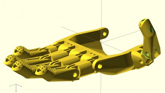
My overall designs for a printable parametric hand are still far from done. And, yet, I’ve come a long long way since jumping headfirst into the realm of open source prosthetics a little more than 30 days ago.12
Forgive the digression, dear reader, before I return you to considerations of prosthetics. After visiting the Asian Art Museum today with the family, I am feeling particularly inspired to discuss dualities.3 I find I am an often-inspired person. This is a very charitable way to describe myself by what would otherwise colloquially and clinically be considered ADHD. When I am inspired by a new topic, I tend to jump right into it – reading voraciously and trying to learn as much about it as I can. When this happens, I also tend to set aside whatever thing I was most recently working on. This means that recently I’ve done little work on drawing robots (big and small) and a multitude of other small projects that would otherwise be just amazing. However, such inspirations/distractions are not only external to a project – but can also be very much internal to a project. Consider, for instance, feature creep – the adding of ever more features to a project, usually at a faster rate than which features are resolved and refined. In order to combat this aspect of my nature, the wanting to add more and better features, I have developed a coping mechanism. To prevent myself from falling down the rabbit hole of features and improvements, I jot them down someplace – either in a blog post4 , in an email to myself, or in a notebook.5 I find that once I’ve externalized and memorialized an idea, I can continue working on a project unfettered and undistracted these other ideas.
To this end, and in the spirit of open source ideals, I will jot down some ideas while I have them:
How large and how small are prosthetic designs typically scaled?
I wanted to have a range of sizes for which my designs were optimized. My guess would be no smaller than 85% and not much more than 160% of the size of the existing Cyborg Beast. Jorge Zuniga was, again, patient enough to discuss this with me. His estimate of a range would be between about 105 – 150%.
What is the diameter of the Chicago Screws typically used in the creation of a Cyborg Beast?
From the retailer’s website, it appears the “barrel” diameter is 0.2 inches, or 5.08mm. I’ll need to make some adjustments to holes for the Chicago Screws in the designs.
How important is hyperextension of these fingers?
The designs of the Cyborg Beast include fingers that can bend “backwards” very slightly. Each finger joint includes a “stop” at the back of the joint. While certainly useful, I question their necessity. I previously designed a connection system for printable snap-fit parts ((For use in an equally noble project)) that connect very tightly and/or bend with a user specified degree of movement. The point with me mentioning these parts is that the “stop” used at the back of each knuckle and joint in the Cyborg Beast may not be necessary at all.
How necessary are metal Chicago Screws to strength and durability of the hand and fingers?
Before you laugh, consider this question – what is the weakest point of any given finger which uses a metal Chicago Screw when having to deal with lateral forces? I would postulate the weakest points would be those thin plastic parts surrounding the Chicago Screws themselves. Thus, even though the hand incorporates metal pins, I have to wonder just how much strength they are providing to the overall device. It would be easy to conceive of a plastic prosthetic hand that was so small that there wasn’t a lot of plastic around each metal screw6. In such a case, the weakest points would be plastic surrounding the metal parts. Extending this conjecture, of what use are metal fasteners to a design that is primarily plastic? The best guess I can offer is that they allow reliable and smooth operation.
Work on proportional fingers
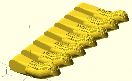
In designing the fingers, I worked to be able to make them customizable in several different ways. The user may specify whether the fingers have the “star grip” pads, whether the finger should be slightly shorter or longer, and scale the finger up or down – without distortion to the hardware and cord channels.
I need to add at least three additional options to these parametric designs. The designs should include the option to add “mouse ears” and easily removable support structures. Additionally, the design should also allow the user to change the diameter of the finger. I did implement this, somewhat, in part of the design. Without implementation throughout the entire design, these partial attempts aren’t helpful.
In creating the fingers shown above, I adjusted their lengths to conform to the measurements of my own hand.7 Next time, I think I would also measure finger diameters.
I think I should create a way to prevent finger parts from being mixed up accidentally while printing. A possible solution is to include “mouse ears” with each finger – but embed an identifying mark in each mouse ear to label the parts.
Ideas on making a better parametric palm
The palm should be redesigned so that the fingers, at the appropriate lengths, would fit into it. I designed the fingers quite a while since working on the palm. I haven’t had a chance to ensure the parts would mesh well without adjustment to the scale.
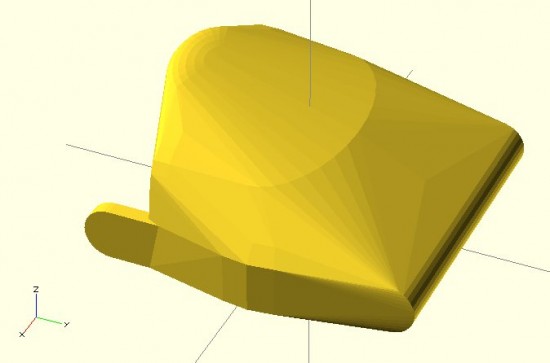
On an entirely different note, I have an idea to redesign the entire palm. By carefully placing deformed spheres, I was able to design a palm. Using a similar process, I subtracted out a void for the user’s hand. The result is a palm with an uneven thickness throughout. Uniform thickness isn’t necessarily an interesting or useful goal. That said, it could lead to a reduction in unnecessary plastic. If I were to redesign the palm, I could design the internal area first8 – and then use the “Minkowski” function to create a uniformly thick shell around the internal form. The bottom would have to be sliced off and the original internal area would need to be subtracted from it.
Ideas on making a more realistic hand
My designs so far are based primarily on the Cyborg Beast, with some minor changes. The “Flexy-Hand” appears to be very organic and realistic. It also features flexible printed connections between each finger segment. Additionally, each finger is comprised of three segments – rather than two like the Cyborg Beast. Interestingly, since the flexible connections between segments allows the hand to return to an “open” position, the hand only requires five tension cords – rather than five tension cords and five elastic cords. The fingers appear to not have any “stops” behind each joint. I have to wonder how having three segments to each finger impacts the function. Does it allow the hand to better grip things? Does it make the hand less sturdy?
Masculine/Feminine hands
One well-intentioned comment to my latest designs is that they are “pretty.”9 While I accept the compliment with the spirit in which it was given, it immediately made me wonder – is the hand I designed “feminine?” Then it occurred to me that with more design effort, I could make “feminine” and “masculine” version of these hands. I think the primary differences would be two-fold – thinner fingers and a less “hefty” palm for a more feminine version and a thicker and perhaps more “blocky” palm for a more masculine hand.
New developments
There have been a number of interesting and new developments and experiments of late.10 In no particular order, these ideas are:
A few days ago my daughter and I were jotting down some ideas in my sketchbook. As we did so, she saw some of the notes from the e-NABLE meeting on 3/21/2014 – including several sketches. We discussed the problem – affordable, customized, and comfortable prosthetics. We talked about amniotic band syndrome, how fibrous amniotic bands affect fetuses, and the different ways in which these bands can cause11 deformities to single fingers, whole hands, and a range of changes in between. I explained how Mr. Jose Delgado Jr. had a $42,000.00 myoelectric prosthetic, the problems he has with that prosthetic, how and why he prefers his $50.00 printed replacement, and how for the price of his one prosthetic people could make 840 more prosthetics.12 She asked, “Why can’t someone use a stump to operate a hand?” I replied that this was exactly how these prosthetics worked – and I drew a few simplified sketches of the Cyborg Beast. Her next question was, “Why can’t it move side to side?” I said that Mr. David Ogreman had designed such a prosthetic.
Default Series Title
My first concrete step was going to an e-NABLE meeting in San Francisco on 3/21/2014. [↩]
The above picture is slightly misleading. I haven’t confirmed that the fingers I’ve designed will properly fit into the palm that I’ve designed – or that the thumb would work at all. Thus, the picture is partially a parlor trick and partially an indication of where I hope to take this design. [↩]
Many of the gods and goddesses in Eastern religions embody dual natures – creation/destruction, life/death, etc [↩]
In one of my several different blogs. Besides, what could be more ADHD than having 3+ blogs?!? [↩]
You may not find this as amusing as I do – but I probably have about four different sketch/notebooks. [↩]
I don’t even know why I’m saying “of late” when I’ve really only been involved a little over 30 days. I guess becuase these developments are new to me? [↩]
Please forgive my lack of a more politically correct term. If you’ve got a better or more sensitive phrase, please let me know as I will gladly adopt it [↩]
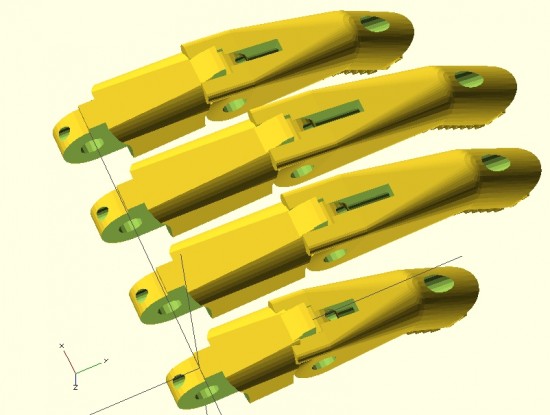
Parametric fingers – different lengths, same scale, with no distortion to hardware
I’m not ashamed to admit it – I’m proud of these parametric designs like few of my other designs. I’ve worked to make this design as customizable and organic as possible. The two modules that define each finger can be customized in two important ways – they can be lengthened1 as well as scaled up or down – without any distortion or change in the size of the holes for the hardware, elastic cords, or tension cords.
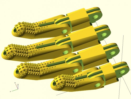
Parametric fingers – with grippy bits
Being able to lengthen2 the finger segments is important because it allows the user to create fingers of different lengths, as normal fingers are of different lengths, all without having to actually scale the fingers to different sizes and without causing a change in each finger’s diameter.
As I’ve discussed in earlier posts, being able to scale the parts up and down without distortion to the hardware holes is important because it allows users to use standard hardware throughout different designs.
For now, it’s back to work on the parametric palm to ensure a proper fit with these parts.
This post is intended as a set of “guidelines” to creating a parametric design in OpenSCAD.
Last Sunday afternoon was spent working out a parametric design for printable prosthetic fingers. Using the OpenSCAD function “hull” it’s relatively easy to crank out a nifty organic appearing design. Admittedly, you have to have a working knowledge the basic union/difference/intersection function first. However, once you do it’s really quite easy.
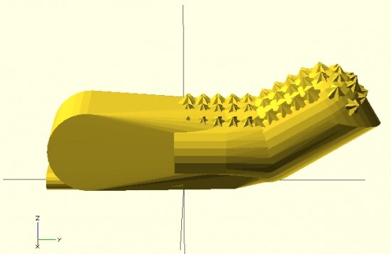
The feature of the design I’m most proud of is the “nail” part of the finger tip. I designed the “nail” by using the OpenSCAD function “intersection()” on two cylinders. The little “nubs”1 consist of a small cube, rotated so a corner is pointed straight up combined, with an identically situated cube rotated slightly.
When I’m designing something to be parametric, I usually don’t really start out designing it that way. I first strive to create a form in OpenSCAD that resembles closely the thing I wish to design. Then, I poke through the design code looking for those elements that are related to the design aspects I’m interested in changing based on parameters. Once located, I replace those parts of the design code with variables that can be specified when the module is called. I realize this is kind of a “high level” description of my design process for parametric things, but it’s still the best description.
Since last Sunday I’ve really done a lot with the design. Some simplifying and a lot of improvements. In the next post I’ll go over these features. I’m really excited to show these off. :)
Above is my first attempt at designing a “solid” finger for the Cyborg Beast DIY printable prosthetic in OpenSCAD.1 The reason this is a “solid” finger is that I haven’t subtracted out any material to allow this partial finger to connect with anything else.
The problem with scaling (up or down) any design that requires fasteners and hardware is that when you do, the holes for the hardware are similarly scaled. This leads to more post-printing work drilling holes to widen them or to find larger fasteners that won’t rattle around in too-large holes.
Thus, if the hardware consists of 3mm screws, the holes for the hardware should be 3mm no matter how much the parts are scaled up or down. To make matters more interesting, not all holes in the model should be excepted from scaling. The above finger tip has a plastic end that is supposed to fit into a mid-finger piece – and those parts should be scaled up or down according to the size of the overall hand. Thus, some voids should be scaled2 and others not at all.3
I’m rather happy with how this finger has turned out so far. It has most of what I understand to be the essential features of the Cyborg Beast fingertips, including little nubs along the finger pad to allow for gripping. I intend to make this an option, in case a user would rather use something like Plasti-Dip to make grippy finger pads, rather than relying on printed plastic bumps.
However, converting a decent design into a parametric design requires a little more work. The way I go about designing a parametric model is to first design one instance of the thing, in this case the finger tip. My next step is to poke through the OpenSCAD code to locate those aspects parts that contribute to the models’ essential features – length of the finger tip, for instance. Once I’ve found these bits, I then try to modify them so that I can insert different variables and arrive at sane variations on the model.
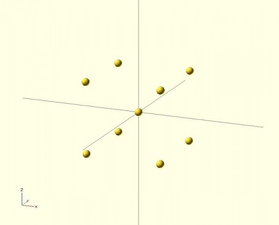
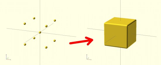
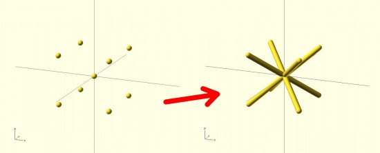
The result looks nothing like a jack! It looks more like a box with rounded edges. The limitation with the “hull()” command3 is that it connects all the outside points from the various shapes. The result is more like what the objects would look like if you covered them in plastic wrap – but not what they would look like if you tried to use shrink wrap.4 However, our goal is to get a jack. How should we go about this? The same way we eat an elephant.56 We need to use “hull()” multiple times7 to connect the central sphere to the eight surrounding spheres.
By breaking the overall design into pieces, you can use the “hull()” command to connect pieces of the design to one another in a seemingly organic fashion. Here’s a set of pictures of my most recent work that uses these design tricks.
I just fired up OpenSCAD, my 3D design program of choice, and then it occurred to me that it’s been quite a while since I’ve used it. A quick search for *.SCAD files on my hard drive revealed I haven’t updated any OpenSCAD documents since 5/13/2012. 1
That’s more than two months! How can this be?! I’ve got a pile of ideas stacking up.
How do you organize your ideas? I created an e-mail address for myself “ideas@DOMAIN.com,” jot down the ideas, and send them to myself constantly. If I have paper, I’ll sketch the idea out, take a picture, and e-mail the picture to this same address. I think I probably send myself about two or three e-mails a day.
I can’t wait to jump back into OpenSCAD and work on some of these ideas!!!
The Thingiverse page actually has a lot of information about the motor mounts. They’re designed in OpenSCAD and are mostly parametric. Since I’m mounting these motors inside a box, the mounts are designed to go into the corners of the box.
OpenSCAD Pirate Ship designed by MakerBlock, printed by BrazenArtifice
I can’t tell you how giddy I get when I see that someone has printed this and uploaded a picture. So, to the eight people who have done so – thank you!
I’ve printed this pirate ship twice and am reasonably satisfied with the result. The first I printed with support structure and the second without. I’m still getting used to Skeinforge v35, so I hope to get a better result. Interestingly, support isn’t really required for the bow!