Printable Parametric Prosthetics and OpenSCAD: Parametric Optimization

Picking parametric fingers

Picking parametric fingers

This post is intended as a set of “guidelines” to creating a parametric design in OpenSCAD.

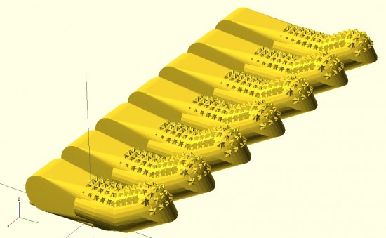
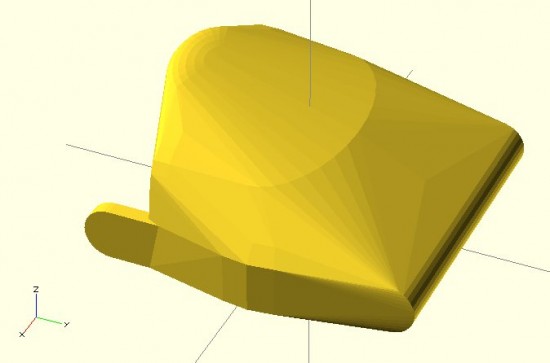
Last Sunday afternoon was spent working out a parametric design for printable prosthetic fingers.  Using the OpenSCAD function “hull” it’s relatively easy to crank out a nifty organic appearing design.  Admittedly, you have to have a working knowledge the basic union/difference/intersection function first.  However, once you do it’s really quite easy.

The feature of the design I’m most proud of is the “nail” part of the finger tip.  I designed the “nail” by using the OpenSCAD function “intersection()” on two cylinders.  The little “nubs”1 consist of a small cube, rotated so a corner is pointed straight up combined, with an identically situated cube rotated slightly.

When I’m designing something to be parametric, I usually don’t really start out designing it that way.  I first strive to create a form in OpenSCAD that resembles closely the thing I wish to design.  Then, I poke through the design code looking for those elements that are related to the design aspects I’m interested in changing based on parameters.  Once located, I replace those parts of the design code with variables that can be specified when the module is called.  I realize this is kind of a “high level” description of my design process for parametric things, but it’s still the best description.

Since last Sunday I’ve really done a lot with the design.  Some simplifying and a lot of improvements.  In the next post I’ll go over these features.  I’m really excited to show these off.  :)

Default Series Title Default Series Title
  1. Meant to give the finger grip and texture []

OpenSCAD Intermediates: How to Make Complex Organic Shapes

Cyborg Beast OpenSCAD prototype

Cyborg Beast OpenSCAD prototype

OpenSCAD tutorials for the MakerBot blog.  In that OpenSCAD tutorial series I covered the basics of the OpenSCAD interface, how to make 2D forms, how to make some basic 3D forms, how to position those forms in 3D space, the different ways to combine forms, how to create mashups of one or more existing STL’s and OpenSCAD forms, how to use modules to reuse your code to make your life easier, how to extrude flat 2D forms into 3D forms, and how to fix design problems.  One of the last tutorials was on how to make organic looking shapes using OpenSCAD.1  However, I have a few design tricks left to share.  A little over 18 months ago I left off the series suggesting as new topics.2 There’s one particular “trick” I am using a lot as I work on designing a printable parametric prosthetic. This trick is somewhat easier to explain using pictures.  Suppose you wanted to make a shape that looked something like a “jack,” but you wanted it to have curved surfaces at the center.  Let’s see what happens when we try to use the “hull()” command.  Do do this, we’ll make a sphere at the center and put eight more spheres around it.  The code for this example is basically irrelevant, but I’ll provide it anyhow.

sphere(r=10);
rotate([0,0,0]) translate([100,100,100*pow(2,0.5)/1.5]) sphere(r=10);
rotate([0,0,90]) translate([100,100,100*pow(2,0.5)/1.5]) sphere(r=10);
rotate([0,0,180]) translate([100,100,100*pow(2,0.5)/1.5]) sphere(r=10);
rotate([0,0,270]) translate([100,100,100*pow(2,0.5)/1.5]) sphere(r=10);
rotate([0,180,0]) translate([100,100,100*pow(2,0.5)/1.5]) sphere(r=10);
rotate([0,180,90]) translate([100,100,100*pow(2,0.5)/1.5]) sphere(r=10);
rotate([0,180,180]) translate([100,100,100*pow(2,0.5)/1.5]) sphere(r=10);
rotate([0,180,270]) translate([100,100,100*pow(2,0.5)/1.5]) sphere(r=10);

There’s a much easier way to create the 8 “orbiting” spheres, but that’s another post unto itself.  :)  Here’s what the above code will create:

Nine little spheres (I named one of them Pluto!)

Nine little spheres (I named one of them Pluto!)

Now, let’s use the “hull()” command to wrap around these spheres.

hull()
{
sphere(r=10);
rotate([0,0,0]) translate([100,100,100*pow(2,0.5)/1.5]) sphere(r=10);
rotate([0,0,90]) translate([100,100,100*pow(2,0.5)/1.5]) sphere(r=10);
rotate([0,0,180]) translate([100,100,100*pow(2,0.5)/1.5]) sphere(r=10);
rotate([0,0,270]) translate([100,100,100*pow(2,0.5)/1.5]) sphere(r=10);
rotate([0,180,0]) translate([100,100,100*pow(2,0.5)/1.5]) sphere(r=10);
rotate([0,180,90]) translate([100,100,100*pow(2,0.5)/1.5]) sphere(r=10);
rotate([0,180,180]) translate([100,100,100*pow(2,0.5)/1.5]) sphere(r=10);
rotate([0,180,270]) translate([100,100,100*pow(2,0.5)/1.5]) sphere(r=10);
)

That code will make this:

Nine spheres to... a box?

Nine spheres to… a box?

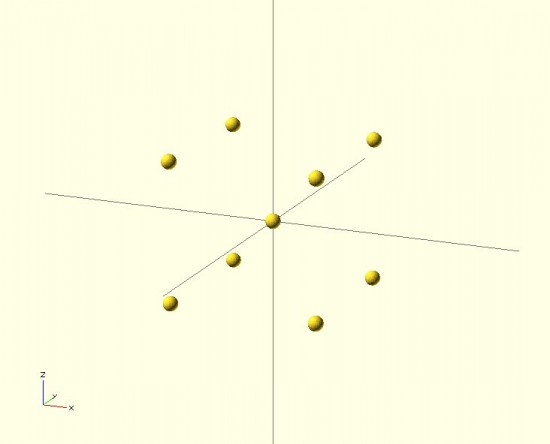
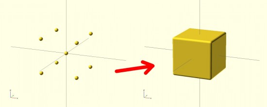
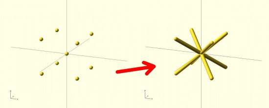
The result looks nothing like a jack! It looks more like a box with rounded edges. The limitation with the “hull()” command3 is that it connects all the outside points from the various shapes.  The result is more like what the objects would look like if you covered them in plastic wrap – but not what they would look like if you tried to use shrink wrap.4 However, our goal is to get a jack.  How should we go about this?  The same way we eat an elephant.56 We need to use “hull()” multiple times7 to connect the central sphere to the eight surrounding spheres.

hull() { sphere(r=10);
rotate([0,0,0]) translate([100,100,100*pow(2,0.5)/1.5]) sphere(r=10); }
hull() { sphere(r=10);
rotate([0,0,90]) translate([100,100,100*pow(2,0.5)/1.5]) sphere(r=10); }
hull() { sphere(r=10);
rotate([0,0,180]) translate([100,100,100*pow(2,0.5)/1.5]) sphere(r=10); }
hull() { sphere(r=10);
rotate([0,0,270]) translate([100,100,100*pow(2,0.5)/1.5]) sphere(r=10); }
hull() { sphere(r=10);
rotate([0,180,0]) translate([100,100,100*pow(2,0.5)/1.5]) sphere(r=10); }
hull() { sphere(r=10);
rotate([0,180,90]) translate([100,100,100*pow(2,0.5)/1.5]) sphere(r=10); }
hull() { sphere(r=10);
rotate([0,180,180]) translate([100,100,100*pow(2,0.5)/1.5]) sphere(r=10); }
hull() { sphere(r=10);
rotate([0,180,270]) translate([100,100,100*pow(2,0.5)/1.5]) sphere(r=10); }

The result would look like:

Much better!

Much better!

By breaking the overall design into pieces, you can use the “hull()” command to connect pieces of the design to one another in a seemingly organic fashion.  Here’s a set of pictures of my most recent work that uses these design tricks.

This slideshow requires JavaScript.

  1. Full list here:

    1. OpenSCAD Basics: The Setup
    2. OpenSCAD Basics: 2D Forms
    3. OpenSCAD Basics: 3D Forms
    4. OpenSCAD Basics: Manipulating Forms
    5. OpenSCAD Intermediates: Combining Forms
    6. OpenSCAD Intermediates: Mashups
    7. OpenSCAD Intermediates: Modularity
    8. OpenSCAD Intermediates: Extruding 2D Objects
    9. OpenSCAD Intermediates: Fixing Design Problems
    10. OpenSCAD Intermediates: How to Make Organic Shapes
    11. OpenSCAD Design Tips
    12. OpenSCAD Design Tips: How to Make a Customizable Thing

    []

  2. These are, in no particular order:

    • How to sketch an object with OpenSCAD
    • How to easily make regular solids – other than cubes and cylinders, like hexagons, pentagons, octagons, etc
    • How to easily make symmetrical solids
    • How to easily make irregular, but symmetrical solids

    []

  3. I almost typed “problem,” but in this case it probably is just a feature []
  4. That’s the best analogy I can come up with []
  5. One bite at a time. []
  6. It’s such a damn shame when a cool domain name is taken – and there’s nothing there.  Such as eatanelephant.com []
  7. 8 times []

OpenSCAD tutorial outline

They’ll continue, but I think the next one will come out on Friday.  So far I’ve covered the interface of OpenSCAD, 2D forms, and 3D forms.

My goal is to show people how to use OpenSCAD in a way that is intuitive and builds quickly on what was taught earlier, with a secondary goal of getting the reader to be able to make something useful as quickly as possible.  Here’s the rough outline/idea of where I’m going:

  1. OpenSCAD interface
  2. 2D forms
  3. 3D forms
  4. Union/difference/intersection
  5. Rotate/mirror/translate/scale
  6. Variables/module
  7. Linear and rotational extrusion
  8. Using other programs to make using OpenSCAD easier (Sketchup, Inkscape, Notepad++)
  9. Include/libraries
  10. Conditional and Iterator Functions

I know I’m leaving a lot out of that outline.  What would you like to see?