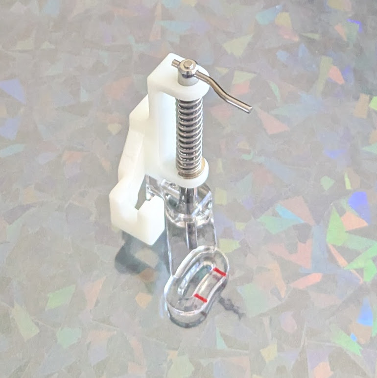
Brother Free Motion Presser / Quilting Foot SA129Apparently I already have one! This is technically the third Brother sewing machine I’ve owned. My first was my Mom’s hand-me-down, which worked for years, then stopped working and was too expensive to fix. :( The second one was also a Brother, that one was fairly inexpensive, but strangely enough some of the rubber wheels inside literally melted into goo. I 3D printed a new one of these wheels, but ended up making everything worse and… once again it was too expensive to repair. I donated both to Goodwill a long time ago in the hopes someone more capable will find and fix them.
In any case, one or more of these sewing machines came with the above free motion foot! On the Brother website it’s listed as the SA129 for $60 and doesn’t indicate it’s compatible with my Brother XM3700. The Brother part elsewhere for only $40 and does indicate it’s compatible with my machine. 1 You can find this exact part available for sale on ebay for under $15, which seems like a pretty great deal. Edit: Ugh, it looks like Amazon has Temu knockoffs for as little as $6, shipped overnight?!2
This little device reminds me of Paul Nosa‘s work with a drawings using a solar powered sewing machine. We’ve seen him at Maker Faire several times – and it’s always a treat to watch him in action. I’m not positive he’s using a free motion / quilting foot for his machine – but it makes sense that’s what he was doing.
The good news is that I don’t have to find this part or wait for it to be shipped. The “bad” news is that I no longer have any excuse for not making something with it!
And, I mean, why wouldn’t it be, really? I can’t imagine Brother would make this one sewing machine not compatible for some reason. That’d be just mean. [↩]
It’s such a simple part, that one of these would work. I’m just torn by my severe dislike for Bezos/Amazon [↩]
When I originally saw the ChompSaw, I had no idea how the thing worked and assumed it was some kind of custom made invention. It wasn’t until much later I learned it was basically a drill + a sheet metal nibbler + plastic box. A maker named Alejandro Leguizamo entered something called the “Builder Box” for the Rocklin Maker Faire in 2025. The description was “Experience the Builder Box! The Builder Box is a power drill accessory which cuts various materials, like cardboard, fabric, and plastic, in a safe manner, perfect for young makers. Test prototypes, share your thoughts, and be part of its evolution.” but I wasn’t sure what it was or how it worked since the only picture was a kind of a logo. I reached out to the maker and it turned out that he couldn’t make it to the event that year, but he explained the project was, as suggested above, a drill + sheet metal nibbler + a box. Suddenly, the logo made sense!
Builder Box Logo
Once I knew what I was looking at, it instantly became easier to find more resources. I found piles of nibblers / sheet metal nibblers for sale online for ~$30-40, several pictures and an unlisted video from ChompShop, and twoInstructables,3 One of the instructables indicated you could use a foot peddle to act as a variable speed controller for the drill. While an interesting idea, I’m not certain the additional incremental benefit is worth the complexity. The ChopmSaw is able to operate at a single speed, so why not this? While an on/off toggle switch is obviously helpful, I’m not going to go out of my way to add this for my own simple prototype/home use. The unlisted maintenance video shows the ChompSaw’s disassembly showing a motor, a nibbler end, bits of wire and such, in a plastic housing, with a fan and tray for catching the cardboard bits – exactly as one would expect.
This slideshow requires JavaScript.
Before I go on, a word about their work station. I got to see one of these at Woodland’s Square One makerspace and thought it was fantastic. It’s cheap, lightweight, sturdy, and attractive. I’m not sure where someone would get the cardboard for these tables, but ChompShop has a guide on building the workstation and an accompanying video. While I would love to have the plans to be able to make one, it’s child sized, would need to be scaled for adult use, and at that point, I really might as well design my own.
I’m reminded of a a guy who invented a simple and attractive business card that turned into a cell phone stand. He went on to create a cardboard furniture / homegoods design studio called “Out of the Box.”4 Like many other people, we accumulate a lot of cardboard. It sure would be great to have plans to draw out designs on cardboard, chop them up with a drill + nibbler, and then fold into furniture.
My understanding of the Gingery lathe is that as you build the device, the portions you’ve built help you build the next pieces. How cool would it be to pick up a nibbler and cheap drill, slap them together, start slicing up parts to make simple mount, then use that to keep building up into a workstation, then desk, then cardboard workshop?
In any case, given the entire project could be basically put together with:
Cheap drill (Harbor Freight has some for less than $20)
Nibbler attachment ($30-$40 at the hardware store or online)
3D printed part to clamp drill in place
Box of some kind
Zip ties to hold drill and clamp in place and hold the drill trigger down or at a certain speed
Extension cord or power strip to turn the drill on and off
Now, I could put my regular corded drill into this, but for an extra $20 I could also have a small dedicated cardboard cutting worktable which seems like a fair investment to me.
Unfortunately, the Maker Faire website regularly wipes out maker entry pages, so I can’t easily link back to the 2023 entry as I would much prefer. [↩]
It’s unclear whether this is the per unit cost from their Chinese factories, to just build a unit, or actual landed cost. I’m guessing landed from their manufacturer. [↩]
Those instructables posted about 9 years ago and 3 years ago, respectively. [↩]
Though, possibly renamed to Creative Cardboard Company now? [↩]
Is there a word for the feeling when you place an online order and the moment you hit “Purchase” you realize there was something else you wanted and now it’s too late? No? Um… me neither.
Since publishing a large blog post about my wishlist / shopping list for building a makerspace two days ago I’ve got two new things to add to the list. I wonder how best to maintain this list. While a wiki would be the best for maintaining evolving content, the tone of my posts tend to be a mix of useful things and nonsense and I’d have to heavily edit / format the content. Maybe one day I’ll get organized and create a page on this site that’s something of a shopping list with links back to the rambling posts.
While I don’t have a ton of uses for a hot foam cutter… but I did purchase some nichrome wire two years ago specifically to make one of these for … reasons I no longer recall. I made the purchase some time in October 2024, so it couldn’t have have been for Maker Faire and likely not for Halloween…
A little extra research brought me back down a rabbit hole to rediscover why I started thinking about hot wire foam cutting.
At Maker Faire 2023 I was excited to see Robert van de Walle’s “composite structures with low VOC materials” 2023 Maker Faire project. The project showed off how he would avoid the use of fiberglass and resins in favor of laminated paper using glue over an insulation foam structure.
Anyhow, I think I was researching these things after Maker Faire because of how miserable it was to cut sheets of foam with a craft knife which then lead to soooo much sanding. I figured in the future I could design something that would let me create almost a small hot wire cutter to consistently and easily cut shapes and beveled edges into foam.
This post has been a long time coming. My kiddo and I made Fallout inspired combat armor out of Harbor Freight floor mats. We’ve now brought these to Maker Faire 2024 and 2025. They’re only $13 for about 16 square feet of 1/2 inch thick sheets of material which was enough for a front and back panel plus enough to do it all again.
I’ll update the photos below with pictures of the finished1 armor. However, below is what it looked like part way through the construction process. We added some 3D printed parts to allow the front and back “plates” to be kept together with some seat belt looking nylon webbing.
This slideshow requires JavaScript.
The very short version of the build guide, for our first simple builds with these mats, would be:
Make patterns on paper or cardboard
Trace and/or cut out of foam using a utility / craft knife you don’t care about because the foam will dull the knife quickly
Bevel/shape/sand as needed
Using gloves, apply a thin layer of contact cement to one piece of foam and the other piece where it’s supposed to go. Let it dry. Then, carefully place one piece upon the other – because the moment the two pieces are joined the contact cement will bond instantly making adjustments2 impossible.
Bevel/shape/sand/paint as needed
If making weathered armor / metallic features, consider using a silver pen or paint to dry brush on the silver color
I tend to take pictures as I build things out of an ambition to turn them into a blog post at some point. So, hopefully these pictures give a sense of how the build went:
This slideshow requires JavaScript.
These were easy enough to create as the entire design was basically just bit flat planks of material. Making more complicated / curved features would probably best be done by using a heat gun to soften and shape or cutting the curved features into flat panels with “darts” / wedges cut out so that when they’re glued together and the form built up, it will take on a curved shape.
The tutorial videos from Robert van de Walle and Evil Ted Smith are absolutely worth watching. The short version would be that when copying another form, you could cover it with aluminum foil, that in duck tape, draw in lines for what could be fairly flat sections, including registration marks, cut the duck tape into flattened sections with “darts” as necessary, trace onto and cut out from foam, heat-shape as necessary, apply and allow contact cement to dry, assemble. Some stills from ETS’s videos might be helpful:
This slideshow requires JavaScript.
These stills won’t do the full videos justice, so you should go watch those. Robert’s point with his short 3 minute video was basically that these materials are incredibly inexpensive, able to build up huge shapes quickly, and look great. I’d agree on all counts.
A friend recently requested some less LLM-centric content. I’ve often said this blog is largely a lab notebook for various ideas or build log. It’s also merely a subset of the stuff swirling around in my brain than a dedication to any one topic. In any case, this post is dedicated to Pete.
I saw the above 3D printed box on Instagram. It looks like a wanted poster from the show “One Piece” of a character named Roronoa Zoro who carries three swords. The box contains a small post in the very center which seems very out of place – until the lights are dimmed and the light under the tip of the post is activated, revealing the light is blocked by the irregular edges of the box and casts a shadow of the silhouette of a figure holding three swords.
I’ve seen other implementations of this stereographic projection technique, but this was easily the coolest. The disparity between the size and shape of the box and shadow was almost startling.
My mind went wild with ideas upon seeing this box. One of the first ideas I had related to some fan-made movie posters by Kevin Collert many years ago.1 Imagine a small projector / box of arbitrary shape that could project that kind of silhouette behind you?
Yeah, a Tony Stark cosplay is neat… but what if you had an inconspicuous stereographic projector on your back that threw up a huge Iron Man shadow behind you!?
This could be extended in any number of ways. A Luke Skywalker cosplay that casts a Darth Vader shadow, Bruce Banner with a Hulk, etc, etc. But, also, what about a shadow of a familiar? A little dragon perched behind you. Or two thugs standing to your side like evil shadow henchmen? Or a crowd of zombies? The neat part about the box / lamp shown on Instagram was that the box didn’t look like it would display that kind shadow of a shadow. It just looked like a box with weird edges to it.
But, how did they do it?
He makes a good point (iykyk)
I’m terrible at Blender. I’ve watched tutorials, tried to use it, but I just can’t wrap my feeble mind around it. My one string is the ability to make things in OpenSCAD. There are plenty of others who can make incredible things in it, but I’m no slouch. The code may not be pretty, but, well, as they say…
And, really, that’s all that counts
I started with a few assumptions.
The light source has to be a single point. If there were multiple LED’s or filaments, it would create fuzzy / duplicate shadow edges. This should be possible with a single bright LED.
The shadow is basically a cone. The edge of the shadow everywhere must be essentially some sort of a distorted cone, with the center point being the single point of light and the edges of the silhouette being the edge of the cone.
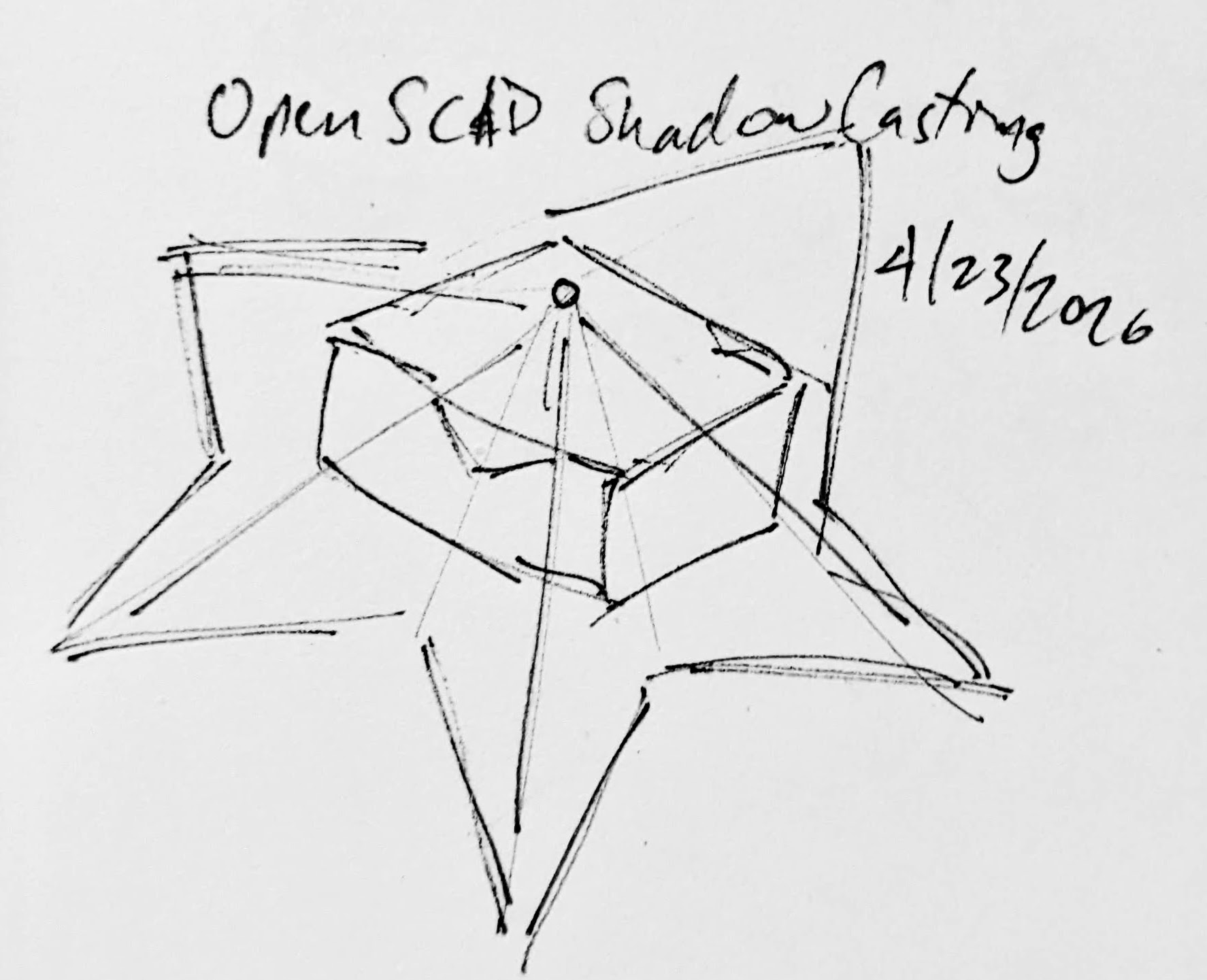
The top edge of the box must be where the cone intersects with the box. If we decide how far off the wall the point of light is and we know where we want the shadow to be and where the shadow edges are, we should be able to intersect the shadow-cone with a thin walled box.
A rough sketch of the idea
Creating the box itself shouldn’t be that big a deal. It’s an easy few lines of OpenSCAD. Creating the arbitrary “cone” was initially a much harder problem. Now, if the design I was trying to create was very simple or entirely convex, I could just use the OpenSCAD hull function around an SVG of the desired shadow and a very small sphere for the point of light. Since a simple shape would be uninteresting, I knew that hull wasn’t going to work. For a while I tried really hard to build a python program that would work by creating a polyhedron built out of the large SVG in the desired location and a very small SVG at the light point – and stitching the sides together programmatically. If you’ve ever worked with the OpenSCAD polyhedron functions, you know what a pain it is. If you don’t define the faces in a certain order or order the faces properly, you’ll end up with flipped faces and a pile of useless triangles. Even when the faces were properly built, the result ended up being difficult for OpenSCAD to render since it involved so many points converging on so few points and weird little overlaps. It was a mess.
I’m listening…
You mean, all I have to do is RFTM? Apparently the linear_extrude function has a parameter called “scale” where you can define how small something should get as it is extruded. This is literally exactly what I needed.
I needed the shadow on the wall to be extruded off the wall as high as the point of light, but scaled down to that same point of light. But, would this work??? I haven’t printed it yet, but I believe it should.
This slideshow requires JavaScript.
From there, the next question is… does this OpenSCAD back-of-the-napkin sketch really work? Again, I’m not sure – I haven’t printed this for a few different reasons. If this design were printed “as is”, there would be a ton of overhangs and support material. I believe when you look at some of the pictures of the lamp lit up from the side, you can see the infill patterns on the sides. I can’t tell from these videos – but I suspect the easiest way to 3D print this box would be to do so in big flat panels. At the point you’re just trying to turn filament into 2D panels, why even bother printing it when you could lasercut it in a fraction of the time?
Let’s look at a few stills of the lamp.
This slideshow requires JavaScript.
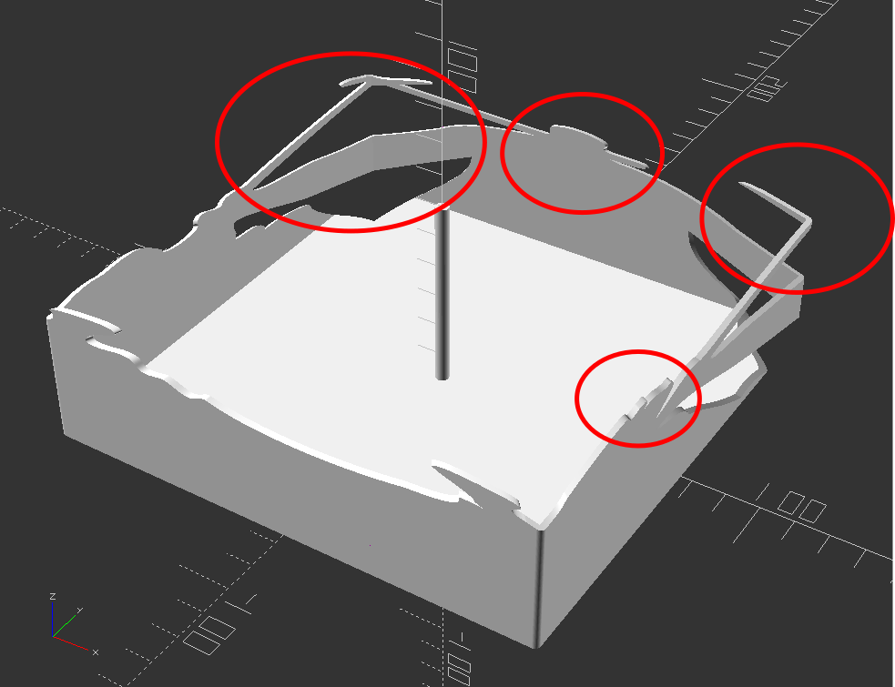
Now, for my quick mockup I just used a simple square shape – but you can definitely see the same features as in the lamp in the video stills. The head, the crossed sword tips at the left, the jagged edges on the bottom right, the floating sword on the right.
Common structural features circled
Given that the theory feels intuitive and sound and that my quick mockup proof of concept seems to have the same structural features as the lamp in the video… this seems like it would work.
If this quick mockup works, then why restrict ourselves to simple boxes? For a mass produced thing you just want to stamp out, a simple box just makes sense. You could lasercut the panels, slap them together, and churn them out all day long. But, the thing that you use to block the light and form the shadow could be any arbitrary shape. It could be a triangle, star, or something far more complex. Here’s another quick sketch:
This slideshow requires JavaScript.
Obviously, this would be a support structure nightmare. But, for a one-off project and a cool enough idea, I think it could definitely work!
His work has been stolen and slapped on so many dropshipped things that it was very difficult to find the original artist! [↩]
It’s always a whirlwind heading into Maker Faire. This year is no exception. This past weekend we got things mostly ready for the Rocklin Maker Faire. All of our robots were functional, which was really great. A quick update to document progress and also act like a to-do list of sorts:
It’s been programmed to “blink” the two LED eyes randomly plus a small number of light shows for the body
Designed/3D printed several eyes, settling on a nice design that should make the eye animations look good
Kim’dael LightningSlayer’s Pendant
The youngest’s project has morphed from an LED arm to a CircuitPlayground in a pendant that just plays some notes when she presses buttons.
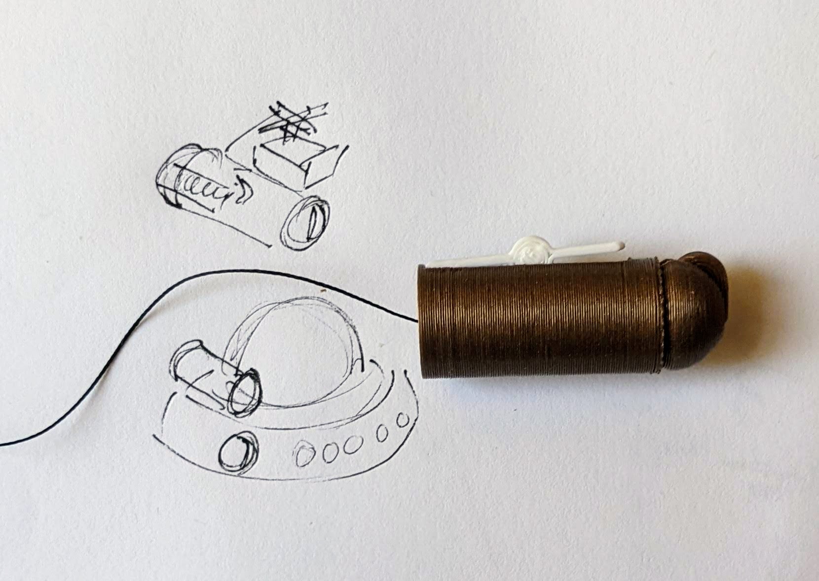
A long extension for the battery pack, using thicker gauge wire wound through the back of stock CircuitPlayground enclosure, is now the “necklace” portion for this project.
Dexter Starfighter’s ED-E
Has a brand new case, a new NeoPixel ring, mount, LED goggles, and a sweet new set of EVA foam armor.
MakerBlock
My robot wasn’t quite ready for Maker Faire last year, but “ready enough” to share. Last year the little bot was just sitting in a jar I carried around and not really visible to anyone.
This year I’ve added feet (entirely cosmetic), changed the battery pack around so it is removeable, swapped out dome diffusers, and am working on new animations/behaviors.
I realized that my old LED goggles were… janky. This was because I had soldered some buttons to one side and then wired them into the Trinket directly, without any resistors. While it /worked/, it caused some problems whenever I pressed a button. I pulled the Trinket out and swapped in my new favorite board, the QtPy.
I really prefer programming / updating via CircuitPython over Arduino since there’s no pre-compile time and fussy Arduino connections.
Besides the programming/uploading, I love the built in RGB, up to 6 capacitive touch sensor, and easy serial communication
As an added plus, I soldered on the 2MB flash chip so the project as a ton of space. 1
And at almost the same price as a Triket ($0.50 more than the original, $0.50 less than the M0 Trinkets), it’s just easier to swap them into any project I would have previously put a Trinket into
Soldering
I’ve really upgraded my soldering experience and it’s made a world of difference. We moved about a year ago and there’s a space in the house where I can keep a soldering station out and ready to use. Just having it available is such an upgrade. I’ve had several handheld / pen style soldering irons over the years and they’re usually pretty terrible. In fairness, this is also because I’m kinda terrible at soldering. I had a basic garbage soldering iron from the local hardware store, upgrade one that had a little temperature control from Adafruit, and then upon the recommendation of a friend upgraded a few weeks ago to an X-TRONIC soldering station.
I gave my old soldering iron to my neighbor so he could work on a project for his wife. As I got to finishing up work on the above projects I realized I couldn’t find my pen soldering iron from Adafruit – and that I didn’t want to find it anyhow. It was fine. It worked. But, my soldering iron holder was cheap and flimsy and easy to tip over and the helping hands I had from Adafruit were “okay” for very small projects, but the joints came loose easily and the helping hands kept falling off. Rather than spend $20 on another soldering iron I would hate, I dropped $70 on the X-TRONIC station which has built in helping hands and soldering iron holder. Setting aside that it heats up very quickly, has good temperature control, melts solder quickly, and has great helping hands… it has a way to hold the soldering iron in a way that isn’t constantly anxiety inducing. 2
Having the soldering station handy has meant I don’t really mind whipping out a quick battery pack extension cable for our projects. I just need to strip some wires, fire it up, drop some solder, and turn it off again.
I may have ruined the first soldering iron tip kinda quickly. Again, I have no idea what I’m doing. I would add solder, dip the tip in flux, wipe on sponge, and then do it all again. This is a terrible process since all it does it add extra contaminants and gunk to the tip, reducing the ability of it to transfer heat effectively. Instead, after watching a video, I learned I should run it at the lowest temperature appropriate for the solder/joint, just dab the tip in the brass wool to clean it up a little, then maybe wipe on the slightly damp sponge, and absolutely coat the tip in solder before putting it down.
Things left to do!
Things to finish
I’d really like to finish up the Fallout themed shirt/vest to go with my project
A way to attach my wife’s octopus to a purse strap
A better way to wear my robot on my shoulder – may use a similar foam paldron
A big chunky seat belt looking thing for the strap wearing my robot
I’ve got designs for a new bag to wear/carry around Maker Faire, but haven’t sewn them up yet – maybe this week!?!!?
Make sure we have
Enough batteries, battery packs, etc for our projects
USB chargers for our LiPo batteries in goggles
Finish my goggles (install battery, update code, possibly change out diffusers
I’m super excited for Maker Faire Bay Area / Mare Island and Mini Maker Faire Rocklin.1 I’m not just excited to see everything, but to show all the things I’ve been working on for a while now. It’s also time to pick up all the little dev boards I’ve somehow accumulated and see if I can make anything with them to show off.
Project Boards
Wemos D1 Mini. A small insanely cheap (~$3?!) WiFi enabled dev board2 , which has 4MB onboard and can run Arduino. I think it can also run MicroPython, but I haven’t tested this yet.
Wemos 600 Pico. An even smaller, even cheaper (~$2 when ordered from China) WiFi enabled dev board that runs… MicroPython? I think?? I’m saying “I think” because I haven’t been able to get it to do anything yet.
As promising asthatseriesofblogpostslooked, I eventually scrapped the Wemos because it was just too much of a pain to get going with MicroPython. I think I could have made it work, but for $7 I could also just use the Adafruit QtPy I already have. The advantages of simply uploading code over a USB cable into a virtual drive just can’t be overstated.
Other Boards
I have a bad habit of picking up dev boards. I’ve got several Adafruit QtPy’s, several Adafruit Trinkets, an Adafruit FX Sound Board, Raspberry Pi Pico (non-WiFi), various Digispark boards, a small handful of ATTiny85’s, and an even weirder assortment of VERY small programmable circuit boards (ISD1806B-COB) designed to go in greeting cards (just 6 seconds), etc.
Companion Robot
Background.
I started this post at least a month ago when I only had a vague idea of what I wanted to make and even fewer skills. After seeing my kid’s companion robot take shape, I wanted to get in on the action and make my own. I decided to make a really small companion robot with just some LED’s, piezo, and small microcontroller unit. I’d taken a stab at making a companion robot a few years ago, but set it aside for a variety of reasons and never went back.
The idea for this new robot would be something a little less ambitious, make more use of NeoPixels than in prior projects3, with a little more interactivity, trying out some CircuitPython, and… let’s be real… more pizzazz!
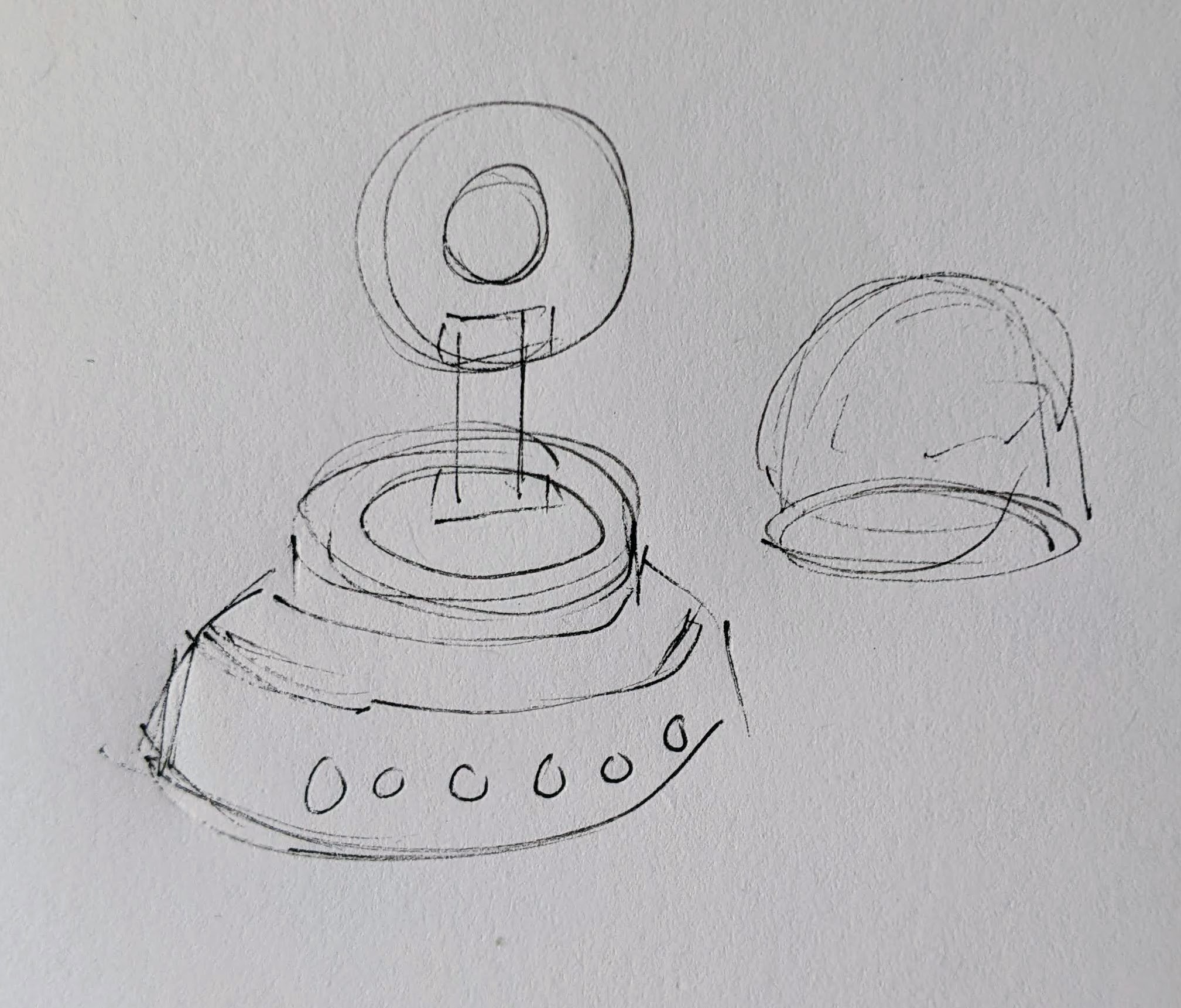
Idea: Friendly Cloud/Vapor/Flame
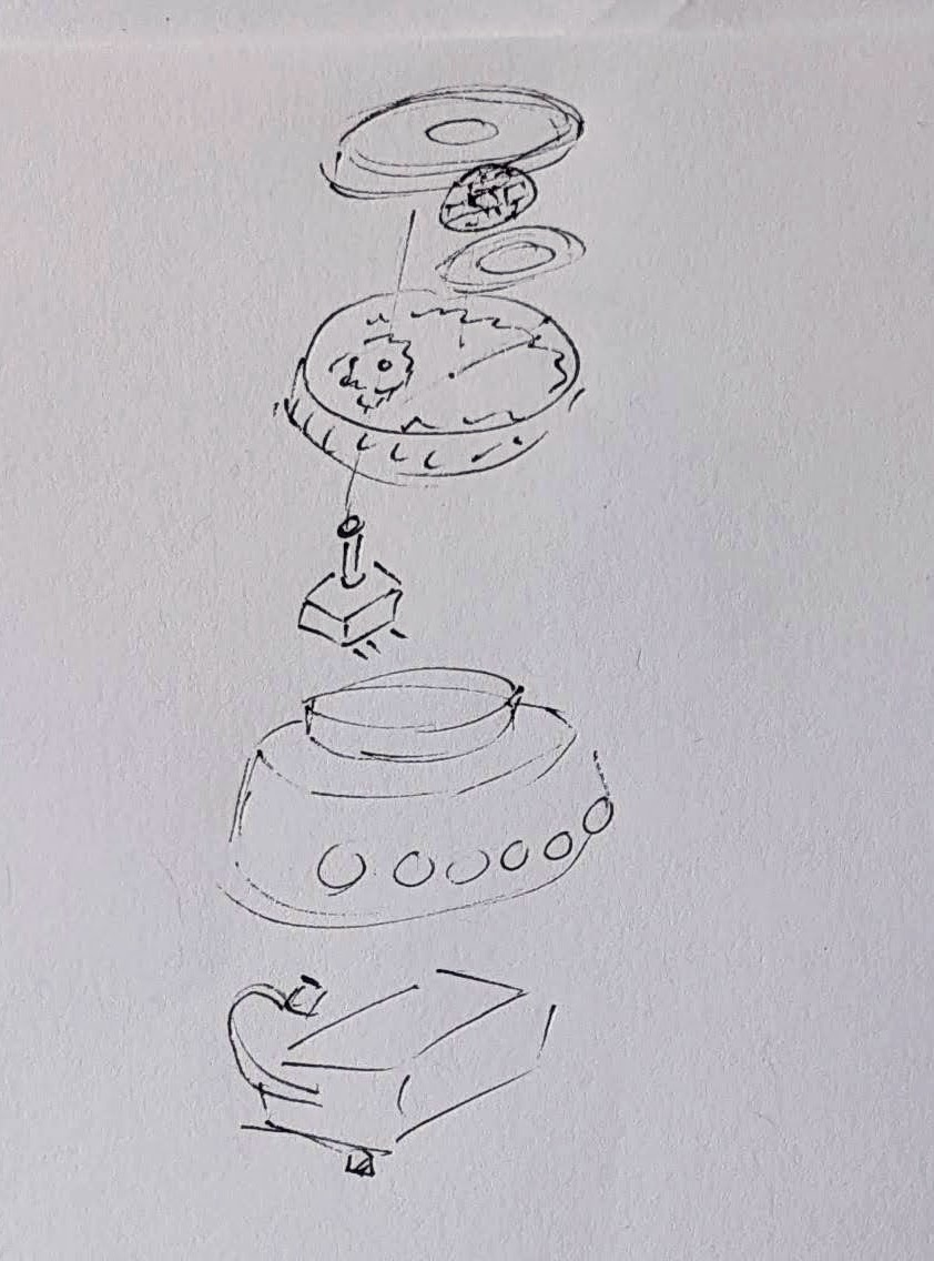
I still really like the copper-toned PLA I’ve been using since it has something of a steampunk flair to it. I settled on repurposing a small plastic enclosure with a clear dome as the “body” for the robot. I wanted it to look something like a small entrapped / captive / domesticated4 sentient cloud of vapor or perhaps flame held within a steampunk enclosure.
As a very small, inexpensive board that could run either Arduino or CircuitPython, I decided on the Adafruit QtPy M0. It could run NeoPixels, there were lots of cool guides on it, plenty of pinouts, and could definitely fit within the confines of my enclosure.
Enclosure:
I started the enclosure by trying to design and 3D print a part to mate with the clear plastic dome. It took a few tries.
This slideshow requires JavaScript.
Once I had that, I extended the base so it could hold more electronics. I could definitely have shoehorned everything into the dome, especially if I took up some of the space inside the dome, but even with an “elevated base” it was still plenty small and could use a battery pack rather than a rechargeable lipo.
Once I had a good design for the enclosure, I tried to make it work with an existing 3xAAA battery pack. In the process I yanked off the connector and ended up soldering the battery pack leads directly into the circuits.
Internal Electronics
I’m just not a great electrical engineer and am still copy/pasting from various guides, tinkering, changing bits of code, swapping out parts, and using “close enough” resistors. Wiring up some LEDs or a piezo to a project isn’t very difficult – it’s some of the more fiddly bits.
Piezo Element Speaker
I wanted to use a piezo buzzer/speaker because they’re large and incredibly thin. They’re not without their downsides. The crystal wafer is also thin and a little fragile. The piezo buzzer without additional electronics has the potential to act as a knock sensor and can generate a high voltage spike which can fry a board. And, without additional electronics, the piezo just isn’t very loud. There are some libraries for the Arduino that basically double the volume of a piezo by connecting it to two pins and then running each opposite of the other, doubling the voltage difference, but they only work for Arduino chips.5
After searching for various ways to increase the sound of the piezo elements, I settled on trying to use the Adafruit piezo amp. I bought two – and tried desoldering the terminal blocks. This completely ruined one. The other one worked great, but for the modest volume gain it was just too big in an already cramped enclosure.
After searching around, I found some amplifier circuits using a small number of common parts.6
Then I tried building an amplifier circuit using an NPN transistor. After reviewing the datasheets for my NPN transistors (and PNP transistors), and breadboarding the circuit with resistors, I sketched it a few times, laid it down with copper tape, soldered it in place with SMD resistors, then pulled it off and placed it onto a piece of Kapton tape and put another piece on top – “laminating” it in place.
Capacitive Touch
Buttons are great and all, but with a capacitive touch pad, I could add metallic elements to my robot rather than a much bulkier button. I bought a few brass upholstery tacks because they looked great – but they just would not accept molten solder. I ended up cutting the prongs short with wire cutters, wrapping the stub with copper tape, then soldering the wires to the tape. I’d also added a little piece of heat shrink tubing over the connection to help keep it together. It’s been working well so far.
LED Animations
As we know from Phillip Burgess‘ incredible “power sipping NeoPixel” guide, we can conserve power and increase the impact of the LED’s by reducing the number of LED’s, keeping max brightness ~20% for a disproportionately large impact, running fewer LED’s at a time, and even running fewer colors at a time. Between Phillip’s work, Todbot’s guide, and the specialized QtPy NeoPixel guide by Kattni Rembor, I was able to put together a few neat animations.
Piezo Sounds
I had a heck of time getting the piezo buzzer to do anything interesting. Fortunately, with my kid helped convert the piano music for “Paint It Black” into tones for me. I haven’t gotten all the note timings right, but I’m working on it!
Future Modifications
More Accessible Enclosure. Right now the “lid” with a hole for the LED ring just sits on the enclosure with a light friction fit. One idea is a hinged lid, either with a conventional hinge or perhaps a hidden swivel hinge. The problem with that, of course, is it requires even more internal space. Other ideas include a ring on top that screws down, holding the top down and in place. I’m crap at designing screw threads, so I’ve avoided this.
Knobs. There’s not a ton of room inside the enclosure, but by including a gear within a gear, I might be able to rotate part of the case and have it manipulate a potentiometer.
Offset gear within gear, manipulating an off-center internal potentiometer
Motors. A robot that just flashes lights and makes a few beeps can still be pretty interesting. However, I have some neat potential features that could be added with just one or two motors. There are some interesting limitations with the current incarnation of this robot and using a QtPy. I’ve only got 10 pinouts7 , 1 for NeoPixels, 1 for the piezo, 6 in use for the capacitive touch sensors, leaving 2 for other potential tasks.8 However, space is already tight so one or two micro servos would be a big space commitment. I’ve seen some really tiny micro servos that might work, but I have no idea where to source them. One silly idea is a “weapons system” using a spring loaded projectile activated by a very small servo.
A small spring loaded projectile launcher, actuated by a small servo
Creating Tone Library. The basic piezo tones are easy enough to play, but including the entire list of tones and the frequencies associated with them seems eat up the poor little QtPy’s memory. I think compressing them into a library might be the way around this issue.
Playing WAV files. WAV files are bulky, but that’s the only sound file format a QtPy M0 can play. However, with the extra 2MB from the SPI chip installed, this shouldn’t be a huge problem. I used Audacity to mix the sound clip down to mono then to 22 KHz sample rate. My preliminary tests worked – but it was incredibly quiet. I haven’t run it through the audio amplifier yet, but I’m planning to.
Sleep / Deep Sleep. Ever since I swapped out the tiny LiPo for a 3xAAA battery pack, I’ve had a lot more battery life, so adding sleep / deep sleep functions haven’t been a priority. However, this inclusion just couldn’t hurt.
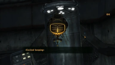
In Fallout New Vegas, ED-E doesn’t use regular dialogue, but communicates through beeps. Basically, he gets <(Emotion) + beeping> as his dialogue. Obviously the only way to research his beeping for this project is to replay Fallout New Vegas and talk to everyone’s favorite eyebot. I came up with a list of some of the emotional beeps he has in the game (and some that I just want) to start programming into him. I have ideas for what I want him to sound like, but I just need to find the right pitches and durations.
By this I mean I am sitting in my room and saying “beep beep” to myself at different pitches in sync with a program I wrote.
Yesterday my dad was checking in on me and how my programming was going and asked how I was doing. I replied, approximately, “bleurrrrghhhhh.”
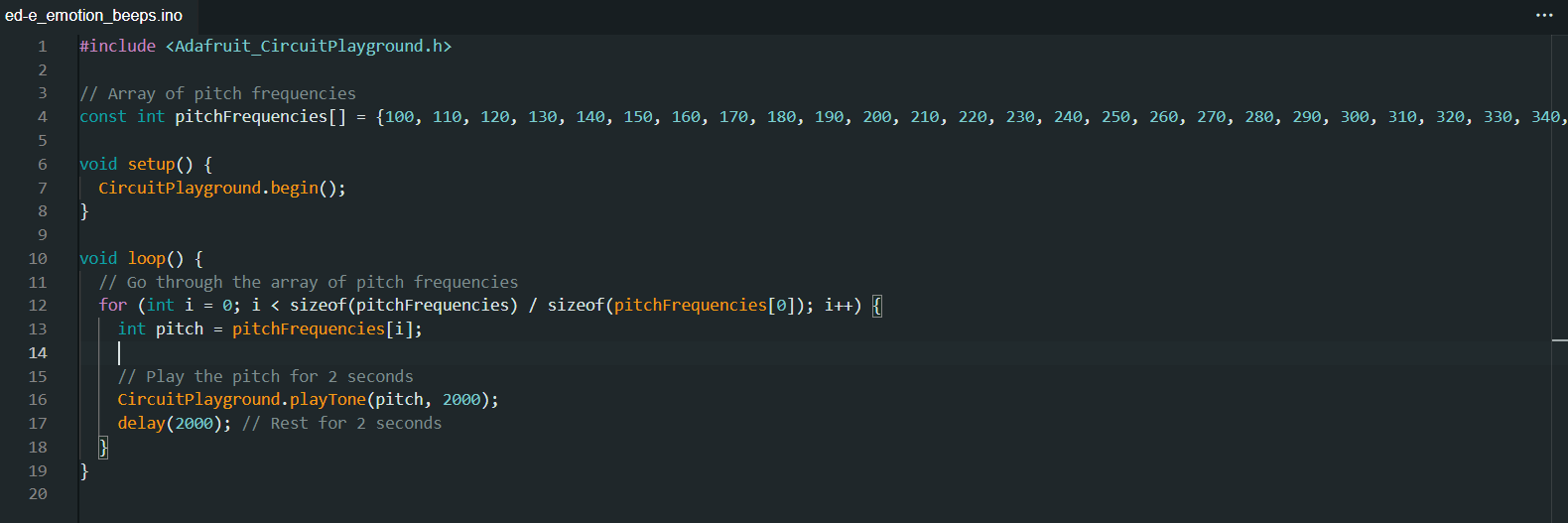
I was having trouble programming the emotional beeps because I have very specific ideas for what ED-E should sound like and no way to get that into a computer. I’m a huge music nerd, but I unfortunately don’t have perfect pitch or some superhuman ability like that to use to get ED-E to sound exactly like I want him to.1 Dad suggested using a loop with an array going up every time, which made everything so. Much. Easier.
This plays frequencies starting at 100hz and going up by 10hz every time. I started with 100hz but going up by 50hz every time, but I liked the specificity of 10hz. Once I get in the ballpark of where I want to be, I can then just run the program and correct the pitches if need be.
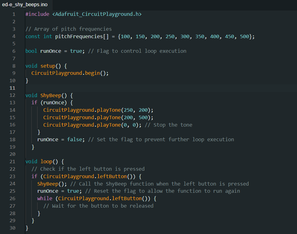
If you read my last post, specifically the spoiler section, you will know why I started with a shy beep. If you didn’t read my last post, go do that! If you didn’t read the spoiler section, that’s fine. What you really need to know is that I want ED-E to make noises.
I’ll admit, this took a while to get right. Not playing the tones or even figuring out what pitches they were or how long they should play for. No, getting the tones to play was easy. Getting them to stop… was much harder.
ED-E was shyly screaming at me on repeat for at least 10 minutes while I was slowly losing my mind and trying to make him shut up.
I turned to ChatGPT to help me fix this, but it was utterly unhelpful and I ended up fixing the problem myself by deleting a bunch of the garbage it generated. Now the problem was that I had to continually upload the code to make the ShyBeep function run again. I was happy that it wasn’t looping anymore, but I wanted to fine tune the beeps and making it upload again and again was a pain. That’s why I decided to make it run when a button is pressed.2
It took a little while to make it run when a button was pressed, but then it would only run once and never again, even if the button was pressed. I finally realized that this was happening because runOnce was set to false, and fixed that.
Now that I have this framework, it has been much easier to program more beeps. Now I have a sad beep, and I’m going to start working on a happy beep because I have had just about enough of ED-E’s negativity.3
I almost decided to use the definitions of pitch from my Rickroll code so I could just ask the computer to start at middle C and go down or say I want the pitch to be a half note in 3/4 time. I then realized I was making this WAY more complicated than it needed to be and just used seconds and hz like a normal-ish person [↩]
I seriously love Circuit Playgrounds. They have everything. [↩]