
I really like 3D printing – but really dislike post-processing. This means I’ll make extra efforts to design things that can just be plucked off the build platform and hand assembled without tools. With my limited build volume, this also means larger objects need to be printed in sections.
I’m very proud of a particular design method in the CuttleBot. I designed the organic and non-angular design of the CuttleBot body by using the “hull” function and several carefully deformed and positioned spheres. However, it would be very difficult to hollow out the interior – since it would mean designing another entire structure to be subtracted out. Instead of creating the outside shape I wanted and using difference to hollow the interior, I designed the interior shape and used that to create the exterior with the “minkowski” function.
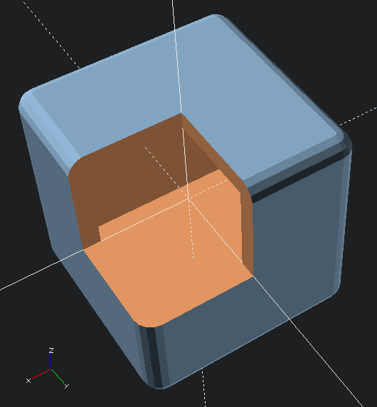
Here’s an OpenSCAD code example:
difference()
    {
    //  Traces sphere around exterior of cube
    minkowski()
        {
        //  Main object
        cube(50, center=true);
        //  Object to trace around main object
        sphere(r=5);
        }
    //  Removing center of object
    cube(50, center=true);
    // Arbitrarily large cutout
    cube(10000, center=false);
    }
Although, now that I think about it, there’s probably an even cooler way to do this! Since the above code needs to refer to the “target” object twice, that code can be simplified by using the “children” function. The below code creates an identical shape.
hollowObject(5) cube(50, center=true);

module hollowObject(thickness)
    {
    difference()
        {
        minkowski()
            {
            children();
            sphere(r=thickness);
            }
        children();
        //  Arbitrarily large cutout
        cube(10000, center=false);
        }
    }
The great thing about a modeling process like this is it allows you to maintain an even thickness all the way around the model. This would be increasingly difficult as the complexity of the underlying model increases.
Lastly, to return to the model, after hollowing out the interior of the CuttleBot, I added areas for the pins to connect the sections together. The body of the robot is in three sections – the head, the mid-body, and the tail sections.
There’s still more to do on the model. Ideally, I’d create a way to open the robot without having to completely take it apart each time. A hinged door would work fine. Also, I should probably add an area where one or more micro servos could be zip-tied or otherwise secured in place. Also, I’ll need to modify the robot’s head later on to allow for multiple (smaller) tentacles and channels for adding wiring for LED’s to the eyes.
There’s also the whole “adding electronics” thing. You know, to make this less a puppet and more a robot.
Companion Robots: Building Robot Friends