
It’s one thing to hack away in CAD software, rendering the idea of a model. It’s another thing entirely to pull it off the print bed and pop it all together.
Last night before going to sleep I started the 2+ hour print job that became the center body piece for the CuttleBot. When I woke up in the middle of the night, I plucked it off the build platform, started the tail section printing (a 90 minute print job), and passed out again. This morning I printed 15 connector pins while getting ready for work.
Just before leaving for work, I yanked out the support structures using some needle nose pliers and popped it all together with the connector pins, and took some pictures to share with you, dear reader.
This was an incredibly satisfying result. Sometimes the work spent on something like the little pins and sockets feels so removed from the design of the main object – so very far from the goals. It feels similar to the work that goes into painting a house – you spend all this time NOT painting before you actually paint. Moving and covering furniture and decorations, taping and masking areas off, removing cabinets and doors. But, as long as I was able to keep my eye on the vision of the final model, laying that ground work on these components meant that I really could assemble a foot long plastic CuttleBot body in a few seconds.
Sigh. At this point, it kinda resembles a CyberMat more than a robotic cuttle fish.
I enjoy sketching out my ideas, so here’s one in case you like looking at them.
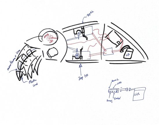
So, what’s left to do? A whole lot. I need to:
- Design newer, thinner tentacles, so I can fit more into the CuttleBot’s head.
- Hollow out the robot’s head or at least create channels for wiring for LED’s inside the eyes.
- There needs to be some mounting areas inside the robot to secure one or two micro servo motors, a small circuit board, a battery, and possibly a few additional components.
- Possibly create a door allow easy access to the interior of the robot. Once I start adding electronics, it might be great to have an on/off switch and nice to be able to connect a USB cable to it to recharge an internal battery or reprogram the behavior.
- Add the electronics and program them.
- This is probably two servos, several chained NeoPixel LED’s, a LiPo battery, an Adafruit Trinket, and possibly a LiPo charger (if I have one lying around).
- If I’m already working towards building a new version anyhow, I might want to drop a few dollars on an OSHPark Board to help make the power from the LiPo easier to route to the servos, LED’s, and board.
However, I don’t think I’m going to be able to finish the robot before Friday.
I think I could probably manage blinking LED eyes by Friday.
Maybe.
Companion Robots: Building Robot Friends