Building a Travel Ukulele: Cutting, Filing, Shaping

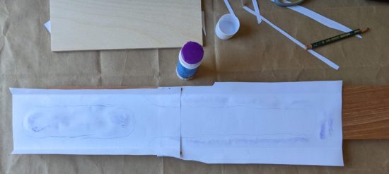
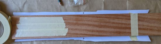
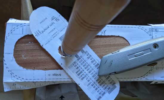
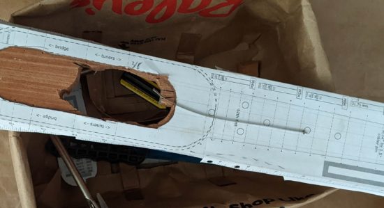
It was going to be hot in California today, so after my morning coffee I went out to the backyard to work on my ukulele.  I already had the center sound hole cut away and part of the neck – now I needed to cut away the excess from along the neck and shape it.

Here’s some photos with some short descriptions.  Some notes on my process after.

This slideshow requires JavaScript.

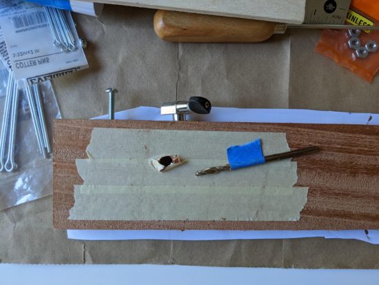
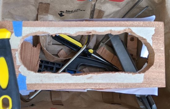
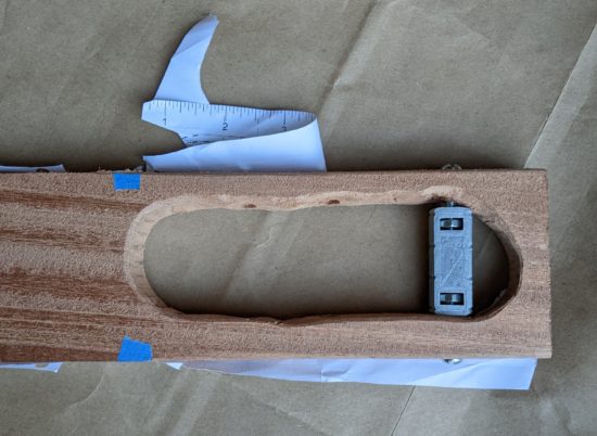
I know the sound hole is wonky.  I’d aggressively attacked it with my most course file, but it’s not a great way to remove excess wood.  I may just up for a slightly lopsided cavity because it will never matter to the sound or the only person who’s ever likely to play it.

The coping saw worked really well today.  The blade that came with the coping saw would probably be described as “fine” and it broke pretty quickly.  After I bought new blades, I replaced it with the most course blade of the assortment which also broke pretty quickly.  I strongly suspect it had more to do with my (lack of) technique than any unreasonable defect in the blades.

This slideshow requires JavaScript.

  • The techniques that probably contributed to broken blades:
    • As I sawed downwards, I would also put a lot of downwards force on the blade.  I found that I was putting force on my thumb along the handle, which created a lot of force on a single point on the blade.  I believe if I had focused on putting force along the teeth, in line with the blade, I don’t think I would have broken the blades as easily.
    • Sometimes, as I was trying to maneuver the blade, I found myself trying to cut an angle by pushing the blade sideways – since it wasn’t possible to rotate the blade since the frame would have been blocked by the neck or the body in some way.  I believe if I’d managed to rotate the blade a little more, it would have allowed me to avoid breaking the blades.
  • Things I should have done better:
    • I should have gone slower or been more careful with the course files.  I added a few more gouges than I should have in a couple of areas.  Hopefully by the time I’m done they’ll either be fixed / filed or sanded out or have become part of the charm and character of the ukulele.
    • When I removed some of the blue tape, it stripped some of the wood off the face of the fretboard.  I’m not sure what I could have done to prevent this.
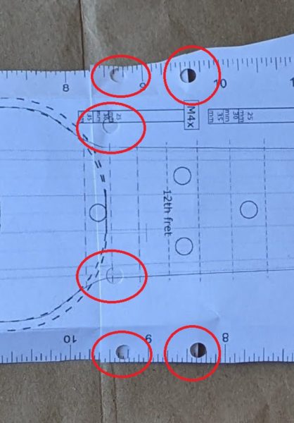
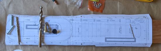
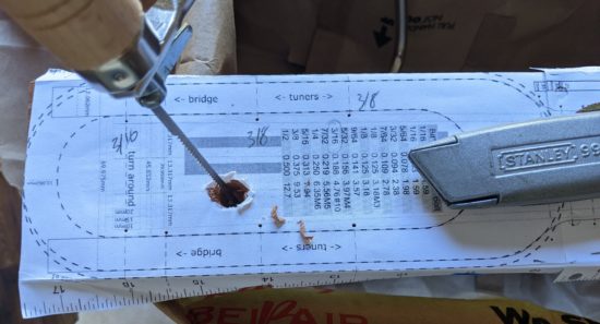
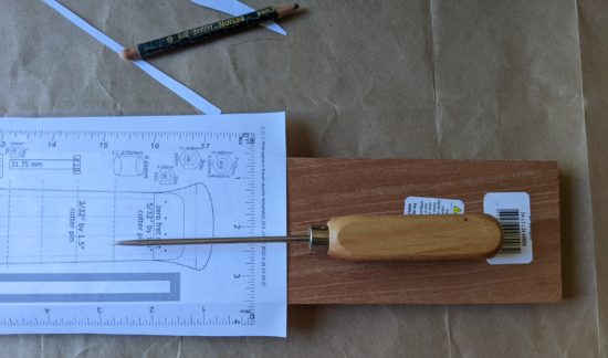
    • Using my awl to mark the board worked well in some spots (way to the sides of the fretboard) and terribly in other areas (around the curve of the body and above where the strings go into the neck).  These are difficult to file or sand away.  Next time I would make lighter indentations as they get closer to the areas to be cut away or just find a way to draw them in with pencil.
  • Things I did that worked well:
    • Making the lateral cuts along the neck (with the hacksaw) really helped.  Not only did it seem to make removing each successive section of wood easier by allowing me to get them out of the way, it also became easier to maneuver the blade without those sections in the way.  It also helped me have little goal posts to point the blade towards as I cut.
    • Rather than using the two “techniques” above, rotating the saw blade when I could or when I couldn’t, some combination of reversing the blade and/or putting the saw inside the sound hole really helped.
    • Still saving the cutoffs so that I can test superglue, wood oil, and wood wax later on.  Excepting the sawdust, I’ve probably saved 95% of the pieces coming off the board.
  • Improvements I may yet make
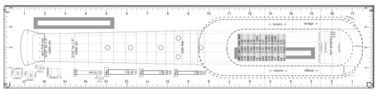
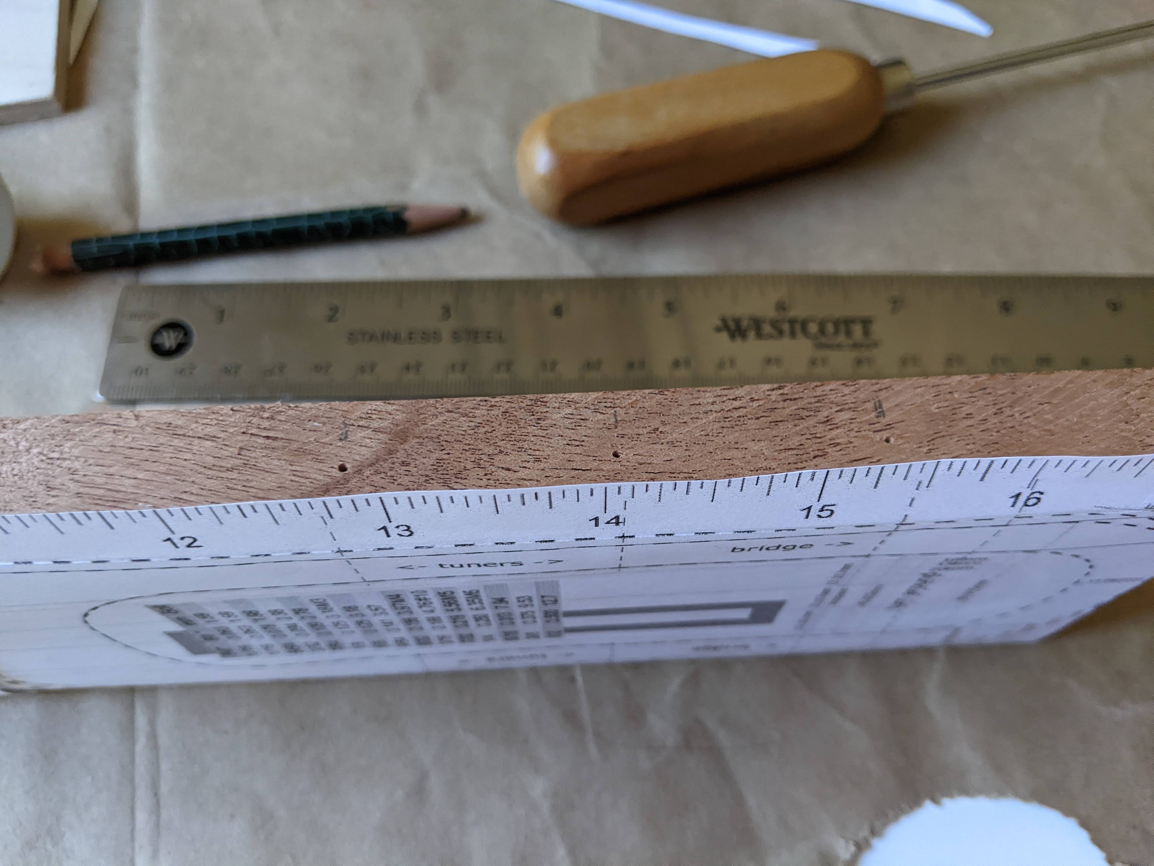
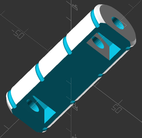
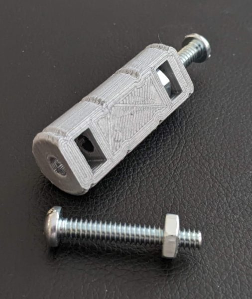
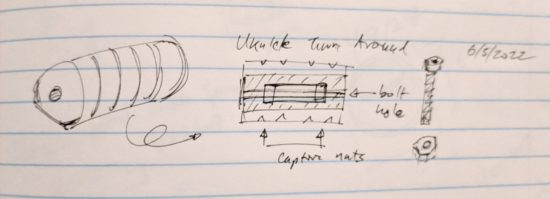
    • I doubt the project requires a solid piece of metal running all the way through the turn around, but I could always swap out one of the two 1.25″ #10-24 machine screws for a 1.5″ screw, to provide more support.  I’m not going to bother doing this unless it looks like the turn around seems to be bowing to the pressure of the four strings.
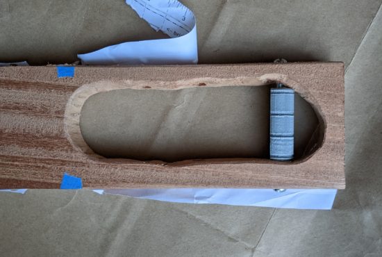
    • I didn’t print the turn around with the highest possible resolution settings.  Even if I had, due to the nature of printing curved top surfaces, it would always look a little rough.  Once the entire ukulele is assembled, it wouldn’t be that big a deal to loosen the strings, pull out the turn around, and replace it with a nicer one.  This could be achieved by simply printing a new turn around with a finer resolution, sanding it a little, and then hitting it with a little spray paint similar to this one at NorwegianCreations.  I would probably print the design with deeper grooves for the strings too.
  • Things I might try on a second go-around
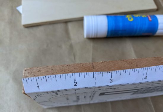
    • The 3/4″ thick plank of wood is a bit thick for the neck.  I suspect I’ll need to file or sand a fair bit away before it feels comfortable and natural to hold.  It’s possible using a thinner piece of wood for the entire project might work out well, possibly down to 1/2″ thick.  The obvious problem with going any thinner than 3/4″ is there won’t be enough material to drill into to install the tuners.  While this could be solved with some 3D printing wizardry, I want a mostly natural wood ukulele, rather than a plastic / wood hybrid.
    • I think a router might be a good way to cut carve this project out.  There are some possible problems, but nothing insurmountable.  I don’t have a work bench or vise to hold the project steady while I routed the wood.  I could possibly work around this by setting the project down on a small piece of plywood, then drilling some scrap wood around it on four sides to keep it from moving.  In thinking back to one of Daniel’s instagram posts, I remembered he used a small router with a roundover bit to make the neck more comfortable to hold.  From the short video, it looks like he’s using the “Drill Master 1/2 HP 1/4″ Trim Router” from Harbor Freight.  It’s $30 right now, but the reviews suggest it’s been on sale recently for as low as $20.  I don’t know if it’s powerful enough to rout all the way through a piece of 3/4″ hardwood.
    • I have some ideas on how I could create a more cylindrical turn around.   It would be to create the turn around in two halves that each have a section the machine screws go through, so that once it’s put together and the machine screws inserted, they’ll stay together.  However, I really don’t think the very slight cosmetic differential is worth the additional effort and engineering time.
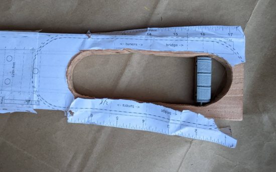
    • There doesn’t seem to be much of a reason, besides spacing, for the turn around to be so far down the body of the ukulele from the bridge.  I would think the turn around could be almost directly under the bridge.  Either way, even if the bridge didn’t have brackets holding it down, it would still be held down in place by the strings pressing it into the wood.  In this case, I would think it possible to create an integrated bridge / turn around.  The real difficulty would be that there would be no good way (absent even more engineering) to make the bridge location adjustable to ensure proper spacing.

The photos above were over the course of about two hours.  I suspect I’ve got another two hours of additional filing and sanding to go – and that’s if I don’t try to file the sound hole to a more symmetrical shape.1

My next steps, roughly:

  • More filing and sanding
    • Filing and sanding down the gouges
    • Softening the corners and edges
    • Adding more of a curve under the neck
    • Moving from the coarsest file down to my finest file then from my coarsest sandpaper to the finest
    • Wiping all the dust off
    • Drilling a slightly larger hole under the neck, so the string knots are buried inside the neck, rather than poking out
  • Super gluing the frets and zero fret
    • Test supergluing the cotter pins to cutoffs
    • Double check all the measurements for the frets2
    • Erasing bad fretlines and drawing in better ones as necessary
  • Wood oil and wax to finish
    • Looking through Daniel Hulbert’s various ukulele tutorials, I found a reference to “Tru-Oil finish with a gunstock wax polishing.”  These appear to be products used for gun stocks, but according to their reviews and several other blog posts out there, other wood projects including guitars!
    • The good thing about these products, the “Tru-Oil gun stock finish” and “Gun stock wax,” is that they’re both reasonably inexpensive and small (only 3oz each).  I don’t plan on making a ton of ukuleles, so I don’t want to end up with piles of power tools and buckets of liquids at the end of this project.
    • I still need to order the finish and wax.  I think I’ll also save some cardboard boxes to build something I can use and leave outside.  I’m thinking of a box with some holes for wooden dowels in the sides, so I can hang the ukulele while in between coats of oil, similar to the way Soph made hers.
  • Tuners, bridge, turn around, and strings
    • As I filed down the inside of the sound hole, it’s been widened somewhat, so I’ll need to measure the spacing and re-print the plastic turn around.  No big deal.
    • Hacksaw off a ~2.5″ wide piece off the 3/16″ zinc round rod.
    • I’ve noticed the strings on my actual ukulele have slight grooves on their underside, on my most played chords.3 The strings are otherwise still good – so I suspect I could pull them off my ukulele and put them into use on my DIY ukulele.  That’s the plan, anyhow.
    • The tuners are easy enough to install.  I’ve test fit them a few times – and looking forward to adding them at last.

Let’s see what tomorrow brings!

DIY Travel Soprano Ukulele
  1. Learning Curves and Ukuleles
  2. Building a Travel Ukulele: Getting Started
  3. Building a Travel Ukulele: Cutting Stuff
  4. Building a Travel Ukulele: Cutting, Filing, Shaping
  5. Building a Travel Ukulele: Filing, sanding, filing, sanding, filing…
  6. Building a Travel Ukulele: Sanding.
  7. Building a Travel Ukulele: Test Fitting
  8. Building a Travel Ukulele: Preparation, Marking and Cutting Frets
  9. Building a Travel Ukulele: Shaping Frets, Sanding
  10. Building a Travel Ukulele: Building a Drill
  11. Building a Travel Ukulele: No Turning Back
  12. Building a Travel Ukulele: Sanding, sanding, and finishing
  13. Building a Travel Ukulele: Finishing, sanding, painting, etc
  14. Building a Travel Ukulele: So Much Experimentation, Bridges, Printing, and Sanding
  15. Building a Travel Ukulele: Plancratineering
  16. Building a Travel Ukulele: Swapping Hardware, Fret Experiments
  17. Building a Travel Ukulele: Bridge, Stringing It Up, and a Sound Test!
  18. Building a Travel Ukulele: Improvements
  19. Building a Travel Ukulele: Back to Basics
  20. DIY Soprano Scale Travel Ukulele
  21. Repairing My DIY Travel Uke
  1. It’s not displeasing or bothersome to me as it is. []
  2. Cotter pins []
  3. Am, F, C, G, E7 []

Building a Travel Ukulele: Cutting Stuff

Today was mostly about just cutting and shaping the piece of wood.  Gallery with descriptions below.

This slideshow requires JavaScript.

What I didn’t really show in these pictures was me shaving the wood with several different hand files and rasps.  One side of the “sound hole” was a lot wider than the other – too wide to put the tuner through.  I made heavy use of my most course rasp to remove a lot of wood from that side, then the more fine rasps to smooth everything out.  I used the smallest of my files to widen the holes for the tuning machines and turn around a little.  These will come in very handy when it’s time to shape the underside of the neck.

I taped the board to protect the pattern, then drew the rough outline on the masking tape.  I did this on the reverse too.

Cutting out the sides of the neck was very slow going with the blade rotated 90 degrees.  As I was cutting, I did think again about how much easier it would be with band saw.  However, I really did want to make this ukulele with hand tools (plus my electric drill), if at all possible.  Plus, I don’t want to buy or even store equipment I’m not going to use all that often.

For anyone following along at home, I think a router would probably be the single best power tool to help on this project.  A quick search revealed routers started at about $60 and scroll saws started at about $110.  If I were to try and make another ukulele, it might be worthwhile to pick up a router.  It probably would have reduced a multi-day coping saw / hacksaw process into about 20 minutes.

Of course, the best overall tool might well be a CNC router.  ;)  That would have made quick work of the entire process… 1

DIY Travel Soprano Ukulele
  1. Learning Curves and Ukuleles
  2. Building a Travel Ukulele: Getting Started
  3. Building a Travel Ukulele: Cutting Stuff
  4. Building a Travel Ukulele: Cutting, Filing, Shaping
  5. Building a Travel Ukulele: Filing, sanding, filing, sanding, filing…
  6. Building a Travel Ukulele: Sanding.
  7. Building a Travel Ukulele: Test Fitting
  8. Building a Travel Ukulele: Preparation, Marking and Cutting Frets
  9. Building a Travel Ukulele: Shaping Frets, Sanding
  10. Building a Travel Ukulele: Building a Drill
  11. Building a Travel Ukulele: No Turning Back
  12. Building a Travel Ukulele: Sanding, sanding, and finishing
  13. Building a Travel Ukulele: Finishing, sanding, painting, etc
  14. Building a Travel Ukulele: So Much Experimentation, Bridges, Printing, and Sanding
  15. Building a Travel Ukulele: Plancratineering
  16. Building a Travel Ukulele: Swapping Hardware, Fret Experiments
  17. Building a Travel Ukulele: Bridge, Stringing It Up, and a Sound Test!
  18. Building a Travel Ukulele: Improvements
  19. Building a Travel Ukulele: Back to Basics
  20. DIY Soprano Scale Travel Ukulele
  21. Repairing My DIY Travel Uke
  1. I’d say once or twice a year I’m tempted to purchase a Maslow CNC kit. []

Building a Travel Ukulele: Getting Started

What would one of my blog posts look like, if it didn’t involve wild digressions?  The saying, “Everyone has a plan until they get punched in the mouth” is attributed to Mike Tyson, speaking of the impending fight with Evander Holyfield.1

I’ll post some pictures, but suffice it to say very little has gone according to plan.  :)

Travel Uke Design
Travel Uke Design

I got started by putting together a pattern based on Dan Hulbert’s designs.  A few notes about how I put it together:

  1. Designs
    1. I started with Dan’s designs, specifically the “backpacker travel ukulele,” added a rounded base similar to his concert sized “travel ukulele,” and then added a number of annotations.  I wanted to have a way to visualize the size of the bolts, hardware, etc.  I also added a grid showing the various drill bits, keyed to the various hardware.
  2. Process
    1. I created the above described design in Inkscape, using different layers for different aspects of the design.
    2. Printed the design on two sheets of paper, lined them up, and glued them together. I used a hole punch in the top sheet, to help line them up easily. I made sure to put the hole punches through parts with lots of detail, but nothing critical to the pattern.
      1. There are rulers on every side of the diagram, and a 100mm wide gray box, because the first several times I printed it out the scaling was all wrong.
      2. I’m not sure why the scaling was wrong – it could have been somewhere in the conversion process from SVG to PDF to a two-page PDF. In the end, I just measured the box, found it was too small, scaled up the next print, and it was close enough to 100mm that it was fine with me.
    3. I picked up the wood (a 3/4″ x 3″ x 24″ mahogany plank from Rockler Woodworking), hardware from Home Depot (I’m pretty sure they lost money shipping me a 4′ long steel bar), and 3D printed the turn around.
    4. I used a pencil to trace the reverse side of the design. This way, I would be sure not to put glue in any of the areas that would touch the final design. I then applied glue and glued the pattern to the wood using a glue stick.
    5. I used a utility blade to cut out the center “sound hole” paper outline, making it easy to cut out the center.
    6. Used an awl to poke holes through the pattern where the strings go above the zero fret, on either side of the frets (so I could draw a line on the wood between these indentations for the fret locations), and other locations where I needed to drill holes.
    7. Taped the bottom of the wood, so that holes drilled and saw cuts wouldn’t cause the wood to splinter. I really should have taped the top too, but I’m learning!
    8. Drilled a hole in the “sound hole” to put saw blade through.
    9. I don’t have a scroll saw, router, drill press, or CNC – any of which would have made the rest of the process a snap. Instead, I bought a coping saw and cut part of the sound hole out.
    10. Snapped the blade. Bought some new blades. Cut the rest of the sound hole out, snapping another blade in the process.
    11. I installed the turn around – which looks like it is going to work well.
  • Hole punches through the top pattern allow the sheets to be aligned properly
  • Paper lined up on the board
  • Drawing on the reverse of the pattern
  • Glue in just the areas not touching the design
  • Glue!
  • Poking holes through the pattern
  • Taping the bottom of the plank
  • Hole through the center, for the coping saw blade
  • Drill bits and hardware
  • Coping saw blade through the hole
  • Center pattern cut out with utility knife
  • Got my awl
  • Marking spots for the awl holes
  • Marking the wood for the holes to be drilled
  • Partially cut, broken coping saw blade
  • Cut out, tape still on
  • Render of 3D printable turn around
  • Printed turnaround with captive nuts and hardware
  • Masking tape removed, filed down somewhat, turnaround installed
  • Turnaround installed and rotated so the captive nuts are out of view
  • Top view

The result is … wildly uneven.

  1. Improvements
    1. As with any project, I find that as I am going through the first iteration2 I discover a few ways to improve the existing plans.  Here are some ideas I had along the way:
      1. Creating the template so that I can fold the left and right sides down and they will indicate the precise location for the tuners and turn around holes.
      2. Including dotted lines from the widest part of the design all the way up – so I can be sure the pattern is straight all the way up the plank of wood.
      3. Create a cross hair pattern for the places where I need to drill, to make my awl punches through the design more precise.
      4. Add measurements to the gray scale boxes.  (Quick tip – the boxes are exactly 100mm long with 0.0mm thick outlines.  This prevents them from being draw very slightly too wide).
      5. Tape the top and bottom of the board, as well as sides, before drilling and cutting, to prevent the wood from splitting or splintering.
      6. Always print at least one extra3 of the pattern.4
DIY Travel Soprano Ukulele
  1. Learning Curves and Ukuleles
  2. Building a Travel Ukulele: Getting Started
  3. Building a Travel Ukulele: Cutting Stuff
  4. Building a Travel Ukulele: Cutting, Filing, Shaping
  5. Building a Travel Ukulele: Filing, sanding, filing, sanding, filing…
  6. Building a Travel Ukulele: Sanding.
  7. Building a Travel Ukulele: Test Fitting
  8. Building a Travel Ukulele: Preparation, Marking and Cutting Frets
  9. Building a Travel Ukulele: Shaping Frets, Sanding
  10. Building a Travel Ukulele: Building a Drill
  11. Building a Travel Ukulele: No Turning Back
  12. Building a Travel Ukulele: Sanding, sanding, and finishing
  13. Building a Travel Ukulele: Finishing, sanding, painting, etc
  14. Building a Travel Ukulele: So Much Experimentation, Bridges, Printing, and Sanding
  15. Building a Travel Ukulele: Plancratineering
  16. Building a Travel Ukulele: Swapping Hardware, Fret Experiments
  17. Building a Travel Ukulele: Bridge, Stringing It Up, and a Sound Test!
  18. Building a Travel Ukulele: Improvements
  19. Building a Travel Ukulele: Back to Basics
  20. DIY Soprano Scale Travel Ukulele
  21. Repairing My DIY Travel Uke

  1. For a short, fun, deep dive on the origins of these quotes, I’d recommend this post by QuoteInvestigator. []
  2. Sometimes the only iteration… []
  3. Probably two extra []
  4. Two is one and one is none. []

Learning Curves and Ukuleles

Watch the curves

Background

About two years ago I received a ukulele for Father’s Day and started playing it.  It’s an instrument I’ve always been interested in, but nothing I’d ever put any effort into. Thanks go a world-wide pandemic1 I had a little extra time on my hands and figured I’d really give this a shot. Who knows, maybe I’d come out the other side of this pandemic with a new skill? Two years on and I can play several songs, carry a tune, and find it relaxing and enjoyable to play.

Focus + Practice + Time = New Skills

Part of my approach was to see if I could set aside some time every day to devote to learning.  I thought back to a TEDx talk by Josh Kaufman entitled, “The first 20 hours — how to learn anything.”  Josh outlines his process for learning the ukulele in 20 hours.

The essence of this talk is stuff we’ve heard a hundred times before.  Small incremental improvements become big gains over time.  Josh cites Malcom Gladwell’s theory that “ten thousand hours is the magic number of greatness” as argued in his book “Outliers” but points out the 10,000 hours is to achieve world-class, expert-level greatness.  Josh argues all you really need is twenty hours of focused deliberate practice to be pretty good at something. 2  This is amusingly similar to the Pareto Principle that “for many outcomes, roughly 80% of consequences come from 20% of causes.”  This 20% of world-class effort, spread out over time, leads to surprising incremental improvements. 3 4  But, effort and time isn’t enough – it’s the particular focus.  Fenyman’s learning technique is uniquely designed to help identify these features.  A gross oversimplification of this method is: write down the steps as if you were explaining it to someone5 , identify gaps6 , organize / simplify and go back to the first step.

My Learning Process

What does all this rambling mean?  This website tends to be my sketchbook / journal for projects – especially projects where I am starting from scratch.  When learning a new topic or skill, my approach tends to be:

  1. Write down everything I know / have learned
  2. Identify gaps
  3. Break the skill into smaller chunks or modules
  4. Research chunks
  5. Memorialize what I’ve learned
  6. [Practice]
  7. Goto line 1

I used a similar process when it came time to build my first 3D printer, my first drawing robot, and vacuum former.  My two year ukulele playing progress could be summarized as follows:

  1. Watched this ukulele tutorial series by “Andy Guitar,” probably dozens of times, while trying to follow along on my ukulele
  2. Found songs using the easiest beginner chords (Am, F, G, C)
  3. Retyped song lyrics, with the chords interspersed, in a way that made sense to me7
  4. Practiced those chords and songs
  5. Found more songs using additional chords (Dm, E7, Em, D, etc) and repeated steps 2-4

Building a DIY Travel Ukulele

But, this post isn’t about playing the ukulele.  It’s about building a ukulele.  Documenting all of this helps me organize my thoughts, get them out of my brain (since I know I can always return here to find them), and free up my attention to move onto new problems.  (Perhaps most importantly, it lets me close dozens of browser tabs.) I’m not sure how I first stumbled across Daniel Hulbert’s YouTube videos and website, but ever since seeing some of his designs, I haven’t been able to shake the idea that I want to build my very own quiet little travel soprano ukulele.

If you’re following along so far, I’d warn you that as I’m writing this I just have a piece of wood with some holes in it and bits of hardware lying around.  I would not consider what I have to be a tutorial at all. 8

Existing Tutorials, Resources, Examples

After looking at Daniel’s various designs, I also looked at several travel ukuleles (most inspired by Daniel’s work):

I designed a 3D printable model, but have yet to print it.  As I worked on the design, I deconstructed other designs I’d seen, looked at the important parts, including some from Daniel’s templates, and tried to keep the critical components and think about the various design choices he made in building his own instruments.  However, I don’t think I ever will try to print this.  From a learning perspective, it was an excellent exercise – but I think I’d much rather have a wooden travel uke.

Anatomy Lesson

First, a bit of anatomy, swiped borrowed from the Kala website.  (I wanted to leave a message letting them know I was borrowing the image, but the post doesn’t allow comments.)

Parts Of The Ukulele - Kala Brand Music Co.
Parts Of The Ukulele – Kala Brand Music Co.

Everything I Know So Far

The following list is a combination of several of Daniel’s blog posts, PDF downloads, and resources he cites.  I will try to include the links to those references.

  1. My Goals

    1. I want to make a soprano size acoustic ukulele with a shape similar to Daniel’s “travel [concert sized] ukulele (2015),” “backpacker travel [concert] ukulele (2015),” and “travel [concert] ukulele (2012)” but using the elements of his “basic hand tools.”  The reason for the soprano size is because that’s the scale of my regular acoustic ukulele.
    2. The reason for wanting to use Daniel’s DIY hardware store components instead of fret wire for the frets is because I want to avoid the pitfalls described by Anders Strand in this blog post.  If the slots for the fret wire aren’t cut to the same depth, well spaced, inserted to the same depth, and leveled properly, the instrument is likely to sound, to use Ander’s word, like “garbage.” 9  Daniel’s “hand tools” ukulele utilizes pieces of cotter pins super glued to the wood in place of this more exacting process.
  2. (Re)Arrangement / Design Considerations

    1. Most of Daniel’s travel ukuleles use a “zero fret” instead of a “nut” to guide the strings on their way to the tuners.  This lets him basically invert the strings, tying the strings above the zero fret where the nut would otherwise be, and place the tuners between the fretboard and the bridge.
    2. Chris Russell’s review of Daniel’s special custom travel ukulele had very few negatives and made a lot of interesting points.  The head of the travel ukulele was tapered so as to allow it to be placed into a holder.  Extending the head a little would allow it to feel more like a full sized ukulele.  Recessing the strings into the head would allow them to be out of the way and less pokey.
  3. Zero fret, frets, bridge

    1. The strings should have a slight incline from the nut (or zero fret) until it reaches the reach the bridge.
    2. Zero fret made from half of a 5/32″ cotter pin
    3. Remaining frets from half of 3/32″ cotter pins
    4. Bridge from a 3/16″ tube (aluminum, steel or styrene), about 3″ wide
  4. Fretboard

    1. Of course, there’s no reason you couldn’t just buy a pre-made/slotted/measured fretboard and glue that down instead of messing with clipping cotter pins in half.  These are widely available on Amazon, with fretboards, slotted fretboards, and pre-assembled fretboards available over at StewMac.com.  If this scratch built ukulele doesn’t pan out, I might give that a try.
  5. Strings

    1. Fret calculator and guidance on how to use it
  6. Tuners

    1. I’ve got these cheap ~$10 tuners on hand, but if this travel ukulele works out alright, I would definitely throw down for a set of the ~$30 Graph Tech tuners Daniel uses.
  7. Super Glue

    1. I’ve always had horrible problems with super glue.  It always dries completely up before I ever get a chance to use it.  Fortunately, my twitter friends came to the rescue and recommended several brands:
      1. Mercury Adhesives M300M (suggested by @EMSL)
      2. Gorilla Glue (@MattStultz)
      3. Loctite (various)
      4. Bob Smith Industries (various)
    2. I haven’t tried it yet, but supposedly baking soda will help super glue cure faster
  8. Wood

    1. Anders recommends against using normal wood in favor of hardwood.  While he doesn’t say why, I suspect it is because the strings were biting into the softer wood, causing the holes to widen slightly, and the ukulele to continually go slightly out of tune.  He suggests the wood could be sourced from a cutting board, which seems like a pretty neat idea to me.
    2. Dimensions
      1. About +16 inches long (extrapolated from design)
      2. About 3 inches wide
      3. About 0.75 to 1.0 inch thick
  9. Turn Around

    1. The turn around could be fashioned from an aluminum tattoo machine grip.  Searching for “tattoo machine aluminum grip” on ebay seems to turn up some acceptable variations.  The most good looking one appears to be about 2″ wide and a little over 3/4″ in diameter.  Ebay links to particular auctions tend to go bad pretty quickly, so without any form of endorsement, I’ll link to the seller here too.  (I’ve tried to save the auction page in Archive.org for future reference).

      This slideshow requires JavaScript.

    2. However, since I have a 3D printer, these seem very printable.  Anders was kind enough to post his 3D models for the parts of his ukulele.  The design of the turn around is pretty simple.  I published my own version on Printables.com.  The model is little more than a 16mm diameter, 50mm long cylinder with a 5mm bore, some ridges for strings (spaced -17.75, -5.5, 5.5, and 17.75 from the center), and a flattened side to make it easier to print.  These measurements came from Anders’ own work.  I suspect the diameter, more, and ridge depths are immaterial, while the spacing is a little more important.
    3. The hardware for the turn arounds were a lot harder to track down.  Daniel uses these super cool screws that go by an absolutely astonishing array of names.  Chicago screws, Chicago bolts, sex screws, posts, binding posts, etc.  Depending upon which one you search for, you’ll either find nothing, lumber, metal stakes, random screws/bolts, or something altogether very different.  I’d found a truly dizzying array of options from McMaster-Carr, Home Depot, Lowe’s, Amazon, and a few other specialty sites.  Fortunately, Daniel was kind enough to point me in the direction of these posts (with a #10-24 coarse thread size) and patiently explain he uses two of these with about 3/4″ of threaded rod between.
    4. There are some really nice looking black oxide posts on Amazon and elsewhere, but they tend to be metric, which then means drilling a metric hole, finding metric threaded rod…  Because I like the look of the black oxide coated hardware, I was contemplating using some metric set screws in their place.
    5. I had considered using just one with a longer #10-24 machine screw10 on the other side – then I realized the screw side would be too narrow, creating a tilted turn around.  Two posts it is.  :)  I don’t know the diameter of the post, otherwise I’d list that here.  Another possibility is using post extensions.
    6. Sometimes as I’m doing a deep dive on a project, I have an idea for an improvement or a way to do something in a different way from the original.  It’s around this point imposter syndrome kicks in and I wonder “Is this actually a terrible idea that was already discarded by others?”  I am sure the main point of having a post / threaded rod / post sandwich for the turn around is to ensure there’s a length of metal running through the turn around.  It’s probably even more important if the turn around is made of plastic.  Then again, what if there was a 3D printed turn around which had two spots for captive nuts and there was space on either side for two long machine screws / bolts?  It would probably have most of the strength of a solid piece of metal running all the way through, far easier to source (and in black oxide hardware!), and fairly easy to assemble.  Printing in plastic allows such cool options, such as embedded / captive nuts, why not leverage that ability here?  A sketch:

      Turn around sketch for 3D model, using captive nuts
      Turn around sketch for 3D model, using captive nuts
  10. Ordering

    1. I haven’t ordered all the parts, but it looks like the most likely route is for me to place an order with Home Depot and Amazon for the various parts.  I’ll post links if/when I get the full shopping list together.
  11. Tools

    1. Drill and drill bits for the tuners and turn around
    2. Hacksaw to cut out the rough shapes, possibly cut threaded rod if I was using that
    3. Coping saw to cut the interior area out nicely
    4. Nippers (left over from some tilework) to cut the cotter pins
    5. Files and sandpaper for taking the rough edges off the cotter pins and shaping the neck
  12. Process

    1. Create template
    2. Transfer template
    3. Drill holes before cutting out the center, this way the wood in the center won’t splinter
    4. Cut rough shape of ukulele
    5. File, sand, and shape
    6. Glue cotter pins
    7. File, sand, and shape
    8. Add tuners, bridge, and turn around

I guess the next step is getting these ideas off paper11 and ordering some stuff!

DIY Travel Soprano Ukulele

  1. Learning Curves and Ukuleles
  2. Building a Travel Ukulele: Getting Started
  3. Building a Travel Ukulele: Cutting Stuff
  4. Building a Travel Ukulele: Cutting, Filing, Shaping
  5. Building a Travel Ukulele: Filing, sanding, filing, sanding, filing…
  6. Building a Travel Ukulele: Sanding.
  7. Building a Travel Ukulele: Test Fitting
  8. Building a Travel Ukulele: Preparation, Marking and Cutting Frets
  9. Building a Travel Ukulele: Shaping Frets, Sanding
  10. Building a Travel Ukulele: Building a Drill
  11. Building a Travel Ukulele: No Turning Back
  12. Building a Travel Ukulele: Sanding, sanding, and finishing
  13. Building a Travel Ukulele: Finishing, sanding, painting, etc
  14. Building a Travel Ukulele: So Much Experimentation, Bridges, Printing, and Sanding
  15. Building a Travel Ukulele: Plancratineering
  16. Building a Travel Ukulele: Swapping Hardware, Fret Experiments
  17. Building a Travel Ukulele: Bridge, Stringing It Up, and a Sound Test!
  18. Building a Travel Ukulele: Improvements
  19. Building a Travel Ukulele: Back to Basics
  20. DIY Soprano Scale Travel Ukulele
  21. Repairing My DIY Travel Uke

  1. I guess that’s redundant []
  2. He references his research for this figure, but doesn’t mention where it came from.  Perhaps it’s in his book?  I checked it out from the library, so I’ll let you know. []
  3. I’m trying to find a good place to mention the Japanese word for the process of continuous improvement is “kaizen.” []
  4. Another great distillation of these ideas is that 1% improvement every day for an entire year yields a 37.78 times improvement overall. []
  5. Thus, these words! []
  6. Thus, the open questions I’ll pose throughout []
  7. I like this style []
  8. A cautionary tale? []
  9. If you choose to go that route, Daniel’s guides should be helpful. []
  10. Machine screws being screws that don’t have a sharp tapered tip []
  11. Or, the screen? []

Building the Monocle Top Hat Cat for #MicrobitVirtualConcert

This slideshow requires JavaScript.

The last few months there have been some pretty amazing little robots posted online for the Tinkering Studio / Exploratorium #MicrobitVirtualConcert.  I wanted to make something and participate and my 6 year old was interested in helping out.  I don’t have a Micro:Bit, but I’ve got a few other microcontrollers and the Adafruit Circuitplayground Express is perfect for this kind of project.

Here was our basic process:

  1. Brainstorm ideas
  2. I eat a frozen pizza and save the cardboard
  3. Sketch of robot – and what it should do
  4. Taping sketch of robot over white cardboard
  5. Tracing sketch with a pencil with enough pressure to leave an indentation
  6. Coloring robot
  7. Measuring / designing a 3D printed plastic part to fit the servo (before I committed more plastic to it)
  8. Scratching my head and jamming together circuitpython code for servos and musical notes together.  I had really wanted to also have the eyes light up with Neopixels too, but…
  9. Ultimately, I had a sketch for lights + musical tones and another for servo + musical tones.  My daughter made the executive decision to go with servo + musical tones. 1
  10. Revising the design to include some “wings” for more surface area to glue to the card board and increase stability
  11. Adding extra “wings” so that the popsicle sticks could pivot on a piece of paperclip in the plastic holder, rather than in the cardboard
  12. “Drilling” holes in the popsicle sticks with drill bits rotated by hand
  13. Gluing in servo holder and just lashing bits of things together in the back with hot glue, blue tape, and some wire
  14. Testing different kinds of tails before gluing the final version in place
  15. The code and STL’s aren’t anything amazing and I didn’t do a lot to comment them.  However, if you might find them useful, I’ve uploaded them to PrusaPrinters.

Here’s the final robot in action:

Companion Robots: Building Robot Friends

  1. Cephalopod Robot Friend, the story so far
  2. Cephalopod Robot Friend Progress
  3. CuttleBot Body and OpenSCAD Design Tips
  4. An Assembled CuttleBot Body
  5. Building the Monocle Top Hat Cat for #MicrobitVirtualConcert
  6. Companion Robots and Maker Faire Season!

  1. What can I say?  In order to bring her onto the project, I had to agree to give her final cut. []

QMK: The Adventure Begins

Richard Feynman
Richard Feynman

Noted philosopher / physicist Richard Feynman has a now-famous method for quickly learning a topic.  It boils down to (a) pick topic (b) write everything you know (c) research to understand gaps (d) simplify.  While I’m not big on biographies, I found this graphic novel version extremely compelling.

I suspect most makers do something very similar to this, whether they realize it or not.  My own variation on this method is to create an outline of what I want to learn with each feature I want to include, do some preliminary internet research, add links to resources to the outline, read, drill down on topics, ask questions, LRR.1

Sometimes I’ll document stuff in a notebook, but when it’s something I know will take some time to learn and probably require code and other digital resources, I like to type them up in blog posts.  It feels therapeutic, getting all this stuff written down.  I think of it as closing mental browser tabs.  Also, by adding links into a post, I can actually close real browser tabs, which is a distinct side benefit.

Quantum Mechanical Keyboards

  1. Falling Down the Mechanical Keyboard Rabbit Hole
  2. A Cornucopia of Keyboard Options
  3. QMK: The Adventure Begins

  1. Lather, rinse, repeat []

A Cornucopia of Keyboard Options

Once I started looking, I found a lot of options for a custom keyboard.  In fact, I started seeing them everywhere.1 I found these offered as some combination of “media,” “macro,” “button,” “board,” “keypad,” and “keyboard.”  I’m offering this list in no particular order – other than how I noticed each one.

 "6 Key Macro Keypad" by @iHayri1
“6 Key Macro Keypad” by
@iHayri1

6 Key Macro Keypad” by @iHayri1, ~$87

I found @iHayri1‘s keyboard in HackSpace magazine, issue #37, page 101.  If you don’t happen to have it lying around – no problem!  This magazine published by the Raspberry Pi Foundation gives away their digital version!  While on the pricier end of the keyboards, it’s got a lot of interesting features.  Six buttons, a media dial, an RGB LED under each key, a series of LED’s at the base of the keypad, and an LCD screen displaying each key’s current function.  I would have ordered this one, except it’s been out of stock for a little while.  :)

"NoodlePad" by @TheMadNoodle
“NoodlePad” by @TheMadNoodle

NoodlePad” by @TheMadNoodle, ~$86

I found the NoodlePad by @TheMadNoodle on Etsy after searching for media keypads.  This is another beautifully designed board – eight buttons, knurled metal knob, mounted onto a shaped board and thick lasercut acrylic plate.  This was the first board I saw referencing “QMK” firmware.  This board is also offered in a “semi-assembled” state where the buyer supplies their own switches and keycaps.  If you’re going to fall down a rabbit hole on mechanical keyboards, the switches may be what get you.  The ordering options also offer “Cherry Red,” “Cherry Blue,” “Cherry Brown,” and “Cherry Black” switches.  At first I thought this referred only to the color of the switch underneath the keycap.  As it turns out, each color matches the little bit of plastic connecting into the keycap which in turn is associated with a different set of mechanical features for that particular kind of switch.  Maybe you want a key with more bounce, requires more force, or a more gentle touch.  That you can order your keypad with the exact keys you need says a lot about this maker and their product.

This slideshow requires JavaScript.

BYO Keyboard” by @travis_the_makr, starting at $36

I happened to catch @travis_the_makr showing off a prototype “BYO Keyboard” on Adafruit’s Show and Tell.  I should probably feel a little bad for hassling Travis to sell me one of these board immediately after his appearance on the show.  Intended as both a way to get started with soldering and programming as well as an actually useful final project. I kinda love the project is powered by an Adafruit Itsy Bitsy M0 so you can use either Arduino or CircuitPython.  I note QMK firmware support is a stretch goal.  :)  Don’t let this bare bones DIY kit without LED’s, knobs, and displays fool you.  If, like me, you’re only now embarking on your mechanical keypad journey and don’t have a drawer full of Cherry MX switches and keycaps, this is an excellent and affordable starting point.  Suffice it to say, I immediately pledged the Kickstarter and am really looking forward to playing with this project.

BigKnob by Leafcutter Labs

“BigKnob” by Leafcutter Labs, starting at $45

Of all the various keypads I’ve looked at, this was the very first one I ordered.  I opted for the version with the black steel case, wonderfully heavy metal knob, and asked the owner for some variation in the keycaps.  Craig shipped the keypad immediately and it arrived well packed in bubble wrap, only requiring that I pop in my choice of keycaps and apply the included sticky rubber feet.2 This keypad rocks four Cherry MX switches, a big hefty knurled metal knob, six RGB LED’s which glow through the lasercut acrylic base plate.  My configuration (with the metal case) was $62, including shipping.  While this is the only keypad I’ve actually used so far, it’s going to hard to top.

“8K Controller” by 2XLNetworks, starting at $32

Once I started tweeting about picking out some keypads, my buddy Pete told me about the “8K Controller” by 2XLNetworks.  This keypad has no LED’s, no metal knobs, no LCD displays – but it doesn’t need any of that.  It comes with a built-in USB cable, you can order it with pre-programmed with custom button assignments at no extra cost, reprogram it if you like, and it unlike a hipster clicky-clacky Cherry MX switch, it rocks arcade buttons.  If you need a bulletproof box that can stand up to repeated abuse at the hands of the public (perhaps for a photobooth, art project, school installation?), this is be the keyboard for you.

Quantum Mechanical Keyboards

  1. Falling Down the Mechanical Keyboard Rabbit Hole
  2. A Cornucopia of Keyboard Options
  3. QMK: The Adventure Begins

  1. I’m reminded of the Baader–Meinhof phenomenon; after the first time you notice something, you notice it more everywhere []
  2. These are a great touch! []

Falling Down the Mechanical Keyboard Rabbit Hole

The Solace of Quantum (Mechanical Keyboards)

TLDR:  I’m going to try some mechanical keyboards to help me work from home and blog about my experiences.

I’m fortunate that I’ve been able to work from home this pandemic.  I’ve always made a special effort to make my work more “digital,” by scanning and organizing digital copies of important work documents.  In many ways working from home hasn’t required too many changes to my overall workflow.  My entire office and desk space shrunk to just a single laptop propped up on a plank of cardboard with some holes to help distribute heat.  I have to be more disciplined about creating digital notes, since I can’t cover my work space in post-its and illegible scraps of paper.  Two pairs of noise cancelling bluetooth headphones are are taking the place of four walls and a door to help me concentrate and communicate “I’m working” to the kids. 1  While I’ve gotten used to one medium sized laptop screen, in place of a dual monitor setup, the one thing that’s been extremely difficult is using a laptop keyboard instead of a full fledged keyboard.

Which brings me, dear reader, to the QMK or “quantum mechanical keyboards.”  The QMK is a keyboard firmware2 that allows you to create very customized keyboards and keyboard layouts.

A while back I wrote a Chrome extension to help me with some work related data entry tasks.  It works by intercepting some of the top row function keys, preventing their default actions, and replacing them with some macros.  This setup probably slashed the number of required clicks and keystrokes by 75%.  My fevered dream is for a custom keyboard which could cut this yet in half.

Now, if that keyboard also has some media controls and sweet RGB goodness, well, then, awesome.  Of course, this means I can’t just go order a keyboard off a shelf.  While there are plenty of neat custom and QMK keyboards, to really get the most out of a board, to get exactly what I need, I will need to roll up my sleeves and actually dive into the firmware itself.

Next up – which keyboards?!

Quantum Mechanical Keyboards

  1. Falling Down the Mechanical Keyboard Rabbit Hole
  2. A Cornucopia of Keyboard Options
  3. QMK: The Adventure Begins

  1. Why two pairs?  I originally bought one for myself and one for my wife, but now I’m just using one while the other charges… []
  2. “Firmware” is nothing more than software built to run inside a piece of hardware []

An Assembled CuttleBot Body

This slideshow requires JavaScript.

It’s one thing to hack away in CAD software, rendering the idea of a model.  It’s another thing entirely to pull it off the print bed and pop it all together.

This slideshow requires JavaScript.

Last night before going to sleep I started the 2+ hour print job that became the center body piece for the CuttleBot.  When I woke up in the middle of the night, I plucked it off the build platform, started the tail section printing (a 90 minute print job), and passed out again.  This morning I printed 15 connector pins while getting ready for work.

Just before leaving for work, I yanked out the support structures using some needle nose pliers and popped it all together with the connector pins, and took some pictures to share with you, dear reader.

This was an incredibly satisfying result.  Sometimes the work spent on something like the little pins and sockets feels so removed from the design of the main object – so very far from the goals.  It feels similar to the work that goes into painting a house – you spend all this time NOT painting before you actually paint.  Moving and covering furniture and decorations, taping and masking areas off, removing cabinets and doors.  But, as long as I was able to keep my eye on the vision of the final model, laying that ground work on these components meant that I really could assemble a foot long plastic CuttleBot body in a few seconds.

Sigh.  At this point, it kinda resembles a CyberMat more than a robotic cuttle fish.

I enjoy sketching out my ideas, so here’s one in case you like looking at them.

It’s NOT a CyberMat! It’s a robotic cuttlefish!

So, what’s left to do?  A whole lot.  I need to:

  1. Design newer, thinner tentacles, so I can fit more into the CuttleBot’s head.
  2. Hollow out the robot’s head or at least create channels for wiring for LED’s inside the eyes.
  3. There needs to be some mounting areas inside the robot to secure one or two micro servo motors, a small circuit board, a battery, and possibly a few additional components.
  4. Possibly create a door allow easy access to the interior of the robot.  Once I start adding electronics, it might be great to have an on/off switch and nice to be able to connect a USB cable to it to recharge an internal battery or reprogram the behavior.
  5. Add the electronics and program them.
    1. This is probably two servos, several chained NeoPixel LED’s, a LiPo battery, an Adafruit Trinket, and possibly a LiPo charger (if I have one lying around).
    2. If I’m already working towards building a new version anyhow, I might want to drop a few dollars on an OSHPark Board to help make the power from the LiPo easier to route to the servos, LED’s, and board.

However, I don’t think I’m going to be able to finish the robot before Friday.

I think I could probably manage blinking LED eyes by Friday.

Maybe.

Companion Robots: Building Robot Friends

  1. Cephalopod Robot Friend, the story so far
  2. Cephalopod Robot Friend Progress
  3. CuttleBot Body and OpenSCAD Design Tips
  4. An Assembled CuttleBot Body
  5. Building the Monocle Top Hat Cat for #MicrobitVirtualConcert
  6. Companion Robots and Maker Faire Season!

CuttleBot Body and OpenSCAD Design Tips

This slideshow requires JavaScript.

I really like 3D printing – but really dislike post-processing.  This means I’ll make extra efforts to design things that can just be plucked off the build platform and hand assembled without tools.  With my limited build volume, this also means larger objects need to be printed in sections.

I’m very proud of a particular design method in the CuttleBot.  I designed the organic and non-angular design of the CuttleBot body by using the “hull” function and several carefully deformed and positioned spheres.  However, it would be very difficult to hollow out the interior – since it would mean designing another entire structure to be subtracted out.  Instead of creating the outside shape I wanted and using difference to hollow the interior, I designed the interior shape and used that to create the exterior with the “minkowski” function.

Here’s an OpenSCAD code example:

difference()
    {
    //  Traces sphere around exterior of cube
    minkowski()
        {
        //  Main object
        cube(50, center=true);
        //  Object to trace around main object
        sphere(r=5);
        }
    //  Removing center of object
    cube(50, center=true);
    // Arbitrarily large cutout
    cube(10000, center=false);
    }

Minkowski sample
Minkowski sample

Although, now that I think about it, there’s probably an even cooler way to do this!  Since the above code needs to refer to the “target” object twice, that code can be simplified by using the “children” function.  The below code creates an identical shape.

hollowObject(5) cube(50, center=true);

module hollowObject(thickness)
    {
    difference()
        {
        minkowski()
            {
            children();
            sphere(r=thickness);
            }
        children();
        //  Arbitrarily large cutout
        cube(10000, center=false);
        }
    }

The great thing about a modeling process like this is it allows  you to maintain an even thickness all the way around the model.  This would be increasingly difficult as the complexity of the underlying model increases.

Lastly, to return to the model, after hollowing out the interior of the CuttleBot, I added areas for the pins to connect the sections together.  The body of the robot is in three sections – the head, the mid-body, and the tail sections.

There’s still more to do on the model.  Ideally, I’d create a way to open the robot without having to completely take it apart each time.  A hinged door would work fine.  Also, I should probably add an area where one or more micro servos could be zip-tied or otherwise secured in place.  Also, I’ll need to modify the robot’s head later on to allow for multiple (smaller) tentacles and channels for adding wiring for LED’s to the eyes.

There’s also the whole “adding electronics” thing.  You know, to make this less a puppet and more a robot.

Companion Robots: Building Robot Friends

  1. Cephalopod Robot Friend, the story so far
  2. Cephalopod Robot Friend Progress
  3. CuttleBot Body and OpenSCAD Design Tips
  4. An Assembled CuttleBot Body
  5. Building the Monocle Top Hat Cat for #MicrobitVirtualConcert
  6. Companion Robots and Maker Faire Season!

Test