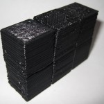
X-Ray view of the 3x2x1 puzzle cube
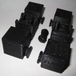
This is easily my most intricate digital design for the MakerBot yet. It’s a 3x2x1 variation on the Rubik’s cube puzzle I had posted earlier.
This version incorporates the prior improvements as well as designing a connector system inspired by R3bbeca‘s beco block connectors.
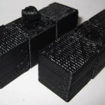
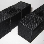
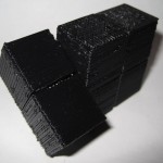
This has enabled a totally printable toy. This just makes me happy. The idea that I can crank out a set of these parts, clean them up a little, and just snap the toy together is just amazing.
TomZ‘s original 1x2x3 “friendlier” Rubik’s cube designs were also totally printable – but required a printed pin that was later glued in place. I like the ideal of all printed parts – but strongly prefer a design that can later be disassembled easily. And, as I mentioned above – the ability to hand assemble the toy is important to me.
I wasn’t able to recreate R3bbeca’s female connector designs so I made a simplified version that should suffice.
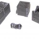
The simplified connection mechanism is essentially two plastic fingers that will (hopefully) pinch the barbell into place. This was made by designing the outline of the gripping “fingers,” creating a horizontal cylindrical hole slightly larger than the intended end of the barbell, then creating a vertical cylindrical hole in the center for the barbell to be inserted through, then a bit of cleanup.
The biggest potential problem is that this design will require a carefully tuned ‘bot. The center cube pieces have a lot of stuff packed in there – semi-circular slots for the semi-circular tabs, connectors for the barbell, and thin walls separating things. With those thin walls and interior overhangs, this may be a difficult design to print.
I think Bender is up to the task, but we’ll see in a few hours. :) I can’t wait to print this!
For me, having a MakerBot is like waking up to Christmas every morning.
Oh, and before I forget, if you want one of these – leave a comment or send me an e-mail through the Contact page. Make me an offer.