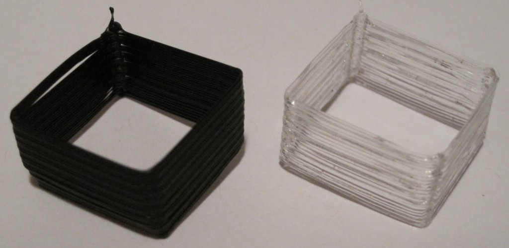
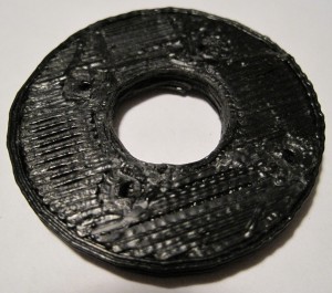
PLA versus ABS, initial thoughts

I’ve yet to print something big as I am still working out some of the black ABS specks from the extruder.  Of the things I have printed so far, it looks like the PLA feels more brittle than the ABS.  ABS will flex slightly when pressure is applied, whereas PLA seems to resist until it snaps.  I like that I’m not wasting PLA by building rafts any more, now that the raft option is turned off in Skeinforge.

PLA takes a little longer to cool which has a few effects on a build.  If the layer underneath is still molten and saggy, the layer on top will sag too.  When an ABS part is done printing you’re basically ready to remove it.  I find that a PLA object can still be a little soft for as much as 15-30 seconds after a build.

I’m loosing finer details on prints.  I just reprinted the toy fire truck swivel.  It turned out really nice except for the actual swivel part.  Unlike the ABS model where the swivel snapped off immediately, the PLA model’s swivel was pretty solid (once it cooled and hardened).  However, it came out too thin!  As I watched it print, the PLA was so warm that it just stretched back during parts of the print – meaning the extruder nozzle made the full circuit, but the plastic stretched a little and pulled back closer to it’s last position.  Uh, that may not sound like the clearest example.

Suffice it to say that small round details such as the swivel didn’t turn out very well.  Which is pretty odd since similar small round detailed parts on the teapot did turn out well.  I suppose part of the reason is the swivel was one small round part where the next hot layer was set down on the prior still hot layer, unlike on the teapot where the thin round spout would be drawn, then the body, then the thin round part for the handle and back over the body – so that by the time the next thin layer was set down the prior layer had cooled.

Skeinforge settings changes

I figured, why not treat this blog as my lab book, right?  It’s a good way to document changes in settings, as well as my rationale for doing so.  Thusly, and without further ceremony, delay, pomp, or ado, I present for your kind consideration and review my latest Skeinforge changes:

  1. Skeinforge->Raft->Activate Raft: checked->unchecked
    • Now that I’m printing in PLA, I won’t need the raft.  As you can probably tell from the pictures below I’ve covered my acrylic build base in blue painter’s tape.  I think I’ll probably just take one of my spare foamcore build surfaces and cover that with blue tape and give that a shot.  I’ve noticed that as soon as my extruder heats up the PLA starts to ooze out.  This isn’t a problem as far as I can tell.  However, it does let some PLA drip – but when I start to run the extruder again it doesn’t extrude at all.  My guess is that the oozing PLA is dripping out of the nozzle, which then has to be filled back up to extrude.  ANYhow, my point is that if I heat up the extruder and don’t immediately start to print it will take a while to fill the nozzle, which means the raft gives the extruder sufficient time to get going before the part is being printed.  Rather than print a raft, waste the plastic, and then have to chip it off later it makes more sense to make sure I advance the extruder a little before I start printing.
  2. Skeinforge->Fill->Infill Solidity (ratio): 0.4->0.3
    • I’ve printed with as little as a 20% fill with no noticeable problems.  I suppose it would really depend on your model.  If the top of the model begins to taper up to a point, then you could probably print with 0% fill.  However, if the top of your build is flat, the topmost layers won’t have much to rest on and will sag just a little.  This doesn’t appear to be a structural problem, but more of an aesthetic one.
  3. Skeinforge->Fill->Infill Begin Rotation (degrees): 45.0->90.0
    • I tried reprinting Zaggo’s whistle in PLA and it didn’t come out – just like it didn’t come out in ABS.  I’m not sure how or why, but my infill rotation got set to 45.  I figure I might have a more solid fill/wall if I had this rotate to 90 degrees.  We’ll find out!
  4. Skeinforge->Fill->Solid Surface Thickness (layers): 3->4
    • This was just a slight tweak to see if I could make solid layers slightly more solid and waterproof/airtight.

PLA success?!

I figured, what the hell – I built it and I can (probably) repair it, right?

So, I backed out the black ABS I have been printing in, jammed in some freaking sweet PLA, ramped up the heat on the extruder to the exact settings I use for ABS, and then FIRE THE MAKERBOT!

For comparison’s sake I used the same exact settings, same exact Gcode file from the last single walled test piece.

What did it look like, pray tell?

I thought you’d never ask.

PLA printing success!

PLA printing success!

How to diagnose and fix a burned out thermistor

Unfortunately, Bender just stopped working.  As I was keeping the nozzle warm while I was working on a new model, I looked up to see a flash of fire/spark shoot out from the nozzle area, ricochet off the build platform, and disappear.  Looking at the RepG control panel I discovered that I wasn’t getting any readings from the thermistor.  Not good.

The RepG control panel showed 0.0 as the temperature, so I shut the plastruder down, not wanting the heater to burn out of control.  I restarted Bender and RepG – but I discovered that while I could control all three axes very slugishly, I could not move the extruder motor or detect temperature.  I’m guess I couldn’t have increased the temperature either, but I didn’t want to try it since I couldn’t monitor the temperature.  That about covers the symptoms.

In order to diagnose the problem I tried to isolate the various parts.  I pulled all of the wires out of the extruder board.  Then, while the wires were still out I tested the nichrome for resistance – still around 6ohms.  Then I tested the thermistor – no connectivity.  Again, not good.  I tested the  motor for continuity, and it was fine.  Since the nichrome and motor seemed fine, that left the thermistor and extruder board.  I popped a random resistor into the thermistor ports, but still couldn’t get a reading on it.  Unfortunately, after several resets of the motherboard and extruder board, I still couldn’t get the motor to move or a reading from the thermistor.  Also, I was getting an error message that the Payload was not big enough.

Rick Pollack of MakerGear suggested on the MakerBot Operators group that I reflash the extruder firmware.  After several failed attempts, I finally figured out how to flash my extruder firmware from the Arduino environment by holding down the extruder reset button.  This got rid of the payload error message as well as the avrdude errors and let me reflash the extruder.

I pulled the entire extruder apart and did a little maintenance.  I flossed the extruder pulley teeth, pulled all the stray bits of plastic out of the idler pulley wheel area, removed the old thermistor, unwrapped the nichrome (which was wound down and then doubled over itself as the original pictures in the wiki suggested) and rewrapped the nichrome (a single layer from the nozzle up the barrel following closely in the threads to make good contact everywhere) as suggested by several people in the MakerBot operators group.  I then tested the nichrome again once it had been taped down for the proper resistance, check.

Once I pulled the thermistor out of the heater assembly, I tested the thermistor at its own leads, rather than at the wires soldered to it (in case the thermistor had come apart from the wires).  Still nothing.  I plugged a random resistor into the thermistor ports and was now able to get a reading off the extruder (as well as move the extruder motor). Concluding my problem was the thermistor, I forged ahead with a plan to replace it.

Luckily, I had placed an order for some PLA and nearly every single part needed for a secondary extruder (or what would be needed to fix a broken extruder) including a new thermistor.  If you haven’t picked up backup parts, I highly recommend it.

I clipped the old thermistor off the wires, pulled out the new thermistor and taped it to a white piece of paper immediately, putting the tape across the leads just below the bead.  I then bent the leads upwards, tinned them, soldered them to the wires, taped down the wires, pulled up the original piece of tape, and then sandwiched the thermistor in tape as per the instructions.  I then plugged the heater, the motor, and the thermistor back into the extruder board – and was able to get a temperature reading, apply a little heat to the barrel, and move the extruder motor.  I also noticed that this removed the sluggishness from the 3 axes stepper motors.

With the heater, motor, and thermistor working separately I put everything back together and reassembled the plastruder, plugged it back into the board and tested it again – readings, heat, and extruder motor working.  I then popped it back into the dinos, did a test extrusion, and starting printing again.

“Rock on completely with some brand new components”
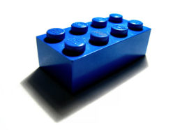
New print: MakerBot Insulator Retainer Ring

Insulator Retainer Ring

Insulator Retainer Ring

Lots of non-robot stuff keeping me busy…  but not too busy to print a replacement insulator retainer ring!  I should really start a list of the first things you should print once you get a MakerBot.  This should be way at the top, even above the Z-axis crank.

From what I gather from the MakerBot operators group, the 5mm acrylic insulator retainer ring that comes with the MakerBot kit will eventually fail.  If this happens, the heater will basically pop off and melt into whatever you were building at the time.

Really, it’s all about choices, right? The extruder motor is super slow but super strong.  Chances are it will eventually deform some part of your assembly.  With this in mind, you can build your heater assembly with and without the nut.  Depending upon which you do, different parts will be bearing the brunt of the force exerted by the extruder motor.

If you assemble the heater without the nut below the washer, the majority of the force will be applied by the motor to the filament and into the barrel and nozzle, eventually forcing the nozzle downwards, ruining the PTFE insulator barrier, stripping the PTFE barrier threads, pushing out the nozzle, and making a molten oozing mess of everything.

If instead you assemble the heater with the nut below the washer, the nut will hold the washer in place and the majority of the downwards force applied by the extruder motor will be placed on the insulator retainer ring.  If the insulator barrier ring fails, it will crack or shatter dropping the heater into whatever you were building.

The good news about the second method is that its pretty easy to print up a replacement insulator retainer ring to keep handy!

MakerBot Raft Settings

I was having some trouble getting my rafts to stick to the build platform until I did the following:

  1. Switched to the acrylic build base (which I promptly pock-marked with a hot extruder)
  2. Changed the Skeinforge raft settings to those suggested on the Thingiverse blog

If you’re having raft trouble, do both of the above and don’t look back.

My first hack

Seeing as how I already had the heater in pieces, I figured it couldn’t really cause that much harm to move the plastruder board.  I totally get why the MakerBot guys put the board on the extruder – that way all you had to do was swap out an extruder and you can roll with a totally new print head.

I don’t really intend to do printing beyond single color plastic.  This may very well change if we see a support material extruder being offered.  But for the foreseeable future, I am really looking forward to printing away with my giant coil of black ABS.

That said, I’m not attached to the idea of having totally modular heads. 1  On the right side of the MakerBot there’s a really large area above the motherboard and to the left of the three stepper motor boards.  The only things preventing the plastruder board from being mounted right there are (1) the motor wires are too short and (2) four holes in the body.

I had dissected a piece of ethernet cable for the wires running to the nichrome wire and thermistor, so I still had four wires left.  I used another two and a bit of solder to extend the wires to the extruder motor.

Sometimes when I need to drill a small hole through soft or thin material I don’t even bother with the drill.  I used a small drill bit with a rubber band wrapped around the non-drill-bitty-end to give it a grip and rotated it into the right panel of my MakerBot.  Bolt it on and…

Presto!  Now I can see all the way through the plastruder.  :)

  1. Sorry about the pun. []

With a little help from my friends

Thanks to the kind folks at the MakerBot Operators Group I’ve been diagnosing what’s going on with my Y axis stepper board and plastruder.

1. Y Axis Stepper Board

No matter what I was doing I couldn’t get the Y axis stepper board to respond to any commands.  Also, the power light on the board would light up as the MakerBot powered on – however it would immediately dim to nothing.  I swapped out every single cable, the motor, and it was always the Y axis board!  Finally, I completely pulled the board off the ‘bot, pulled every cable, and started adding the cables back one by one… and it worked!

I was concerned with why it wasn’t working, but happy it was working.  So, I bolted it back on, connected the wires… and it didn’t work any more!  What went wrong?  It was one of the opto-endstop cables.  I discovered that when I connected the front opto-endstop cable it would kill the power to the Y-axis board – or any other board!

The Y-axis three prong cable is easy to insert upside down.  And that’s what I was doing – because it fit better in that orientation.  Well, flip it upside down and rock on!

2. Plastruder / Extruder Temperature 0.0

Now that I could manipulate the 3 axes, I tried to use the plastruder.  I noticed that even at room temperature the thermistor was reading 0.0.  Also, the heater was smoking a little, I could smell something burning faintly, and the extruder was oozing something clear and sticky.  Not ideal.

With a lot of help from the guys at the MakerBot Operators Group I attempted to diagnose the problem.  Here’s what I tried:

  • Testing the resistance of both the nichrome and thermistor while both were still plugged into the plastruder board.  Both seemed okay – but I still could not get a reading from the thermistor.
  • One suggestion was to plug a random resistor into the thermistor ports to see whether the board and software was receiving information.  Being a complete novice and having zero spare parts around, I actually had to make a trip to the local electronics store for a single resistor. 1  Once plugged in the resistor (a quarter watt 10k) must have been resisting stuff because the board interpreted it as a temperature.  Thus, the board and software are probably fine. 2
  • Thus, I disconnected the heater wires and thermistor wires and tested them away from the board.  I really should have done this in the first place.  It would have told me that the thermistor was either burned out or no longer connected to the wires.
  • Taking the heater apart was almost painful.  The ceramic tape was a little scorched, parts of the kapton tape closest to the print head were actually burned to a blackened crisp and flaking off.  It was just not pretty.
  • The nichrome seemed to still be intact and giving the proper resistance, but the thermistor was not showing connectivity.  I was pretty bummed that I may have cooked it.  But, when I started to peel that tape away, I tried to test the resistor leads – which did show the proper resistance!  I checked the connections between the thermistor leads and the solder and discovered that one of the leads had lost its connection with the solder/wire.
  • I then tried to resolder the wire to the thermistor and then rewrap it into the kapton tape and tried its resistance again – and got a proper reading.   Then I taped it to the extruder head, to see if I could get a heat reading off of it – and I did!
  • This time, I went VERY slowly.  I tested the heater/extruder head completely apart from the printing assembly with the thermistor taped to it – I could heat and read the temperature.  I then wrapped it in tape, tried again, success again.  Then I wrapped it back in the ceramic tape, heated/read again with success.  Then I put the assembly back on the plastruder, heated/read again.
  • Now, a decision I made that I may very well regret later was to leave the nichrome wrapped as it was and not pull it all off and rewrap it.  The testing showed it was intact, it was still in its fiberglass insulation, and I had done a pretty good job of wrapping it in the first place.  In rewrapping the heater I took out as much of the burned kapton tape as I could and then wrapped it back up.
  1. I picked up a lot of other stuff while there, but this a single resistor was the actual purpose for the trip. []
  2. Thanks Rick Pollack! []

Things I learned while assembling my MakerBot

I’ve assembled quite a lot of my MakerBot today.  This entailed assembling and putting together the X axis stage, Y axis stage, pulleys, putting gears on stepper motors, mounting gears, putting in the slider rods, Z axis threaded rods, bolting on the motors, and assembling the two “dinos.”

  • If you’ve got a Batch 9 MakerBot, definitely install the Z-axis after assembling the body of the MakerBot.
  • Put off adding the Z-stage/extruder-stage for as long as you can.  It will just be in the way.
  • Keep that sandpaper handy – you may need to sand down some tabs or widen slots or holes to make things fit, especially if you painted your MakerBot.
  • If the smooth slider rods are just a smidge too short, they will slide back and forth causing a little extra noise as your MakerBot operates.  I haven’t gotten mine running yet, but I have read this is the case.  I noticed that one of the slider rods for the X axis on my Batch 9 MakerBot was about 1mm too short.  When I put the caps on, I noticed that it still had some wiggle room.  I took a scrap of paper towel, folded it up so that it would push up against the end of the rod, and clamped it down.  There’s no wiggle room now, so hopefully that’s it.
  • Make sure the top bearing is just under the top edge of the top panel.  This is in the directions, but it’s really important to make sure everything spins freely.
  • Putting gears on the stepper motors is tough!  Even when you back the tightening screws on the gears out as much as you can, the fit is incredibly snug.  I eventually sanded the inside of the gear slightly, put the motor on cardboard, and then pushing downwards slowly and forcefully.
  • When you’re installing the geared belts, get them as level as you can manage.
    • For the top stage this will involve adding/subtracting washers/nuts from the printed pulleys as well as adjusting the gear’s placement on the stepper motor.
    • For the X and Y stages, the height would essentially be dictated by the height of the belt on the clamps.  The height of the belt on the clamp is essentially set, so the pulleys and gear on the stepper need to be matched to that.
  • When assembling the carriages with the plastic sliders, the instructions suggest you may need to sand the circular hole they fit into.  Just make a point of sanding them, if they’re tight they could affect the looseness of the stage on the rods.
  • Inspect your Y-stage pulley (this is the smallest printed pulley) to make sure the top is level and there are no protuberances.  Even a little bit of a nub will prevent it from rotating properly.
  • The easiest way to remove the itty-bitty sticky-paper protective acrylic cover is to use a razor blade or exacto-knife to pop them off.  You probably don’t need to, but it’s an aesthetic thing.