Print 5: Replacement toy fire engine part

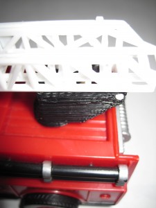
Here’s another part I printed.  The original piece was from a toy fire truck.  It served as a rotating platform, hinge, and guide for the fire ladder.  The toy broke when the part was pushed laterally, shearing the axle off.  Overall, I’d say it was a poorly designed piece.  The entire toy would have been much sturdier if the axle stuck out from the body of the truck in the form of a low round stub the rotating platform fit around.  However, I’m rarely consulted in the engineering of toy fire trucks.  :)

As with the window latch, I had taken the measurements and modeled the piece in Google Sketchup several months before ever purchasing my MakerBot.  I had to make several small changes to the design of the part to reduce overhangs.
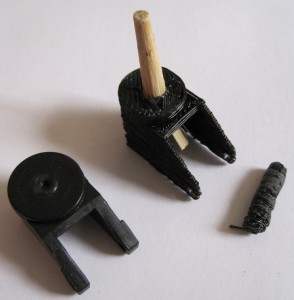
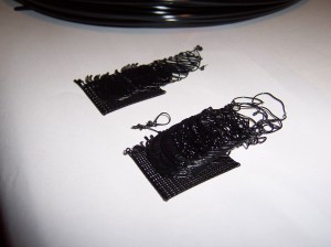
Replacement toy fire truck part, for comparison

Replacement toy fire truck part, for comparison

Replacement toy fire truck part

Replacement toy fire truck part

This wasn’t the cleanest piece I’ve printed, but it’s fine for a part that is destined to be broken all over again.  If I were printing it again I’d widen the two walls which serve as the hinge to the ladder.  The piece I printed had the same kind of unevenness in the tall thin axle that I had on the handle of the Z-axis crank. The part became so blobby that I tried to sand it down to be more even – and accidentally snapped the axle off.  Hence, the piece of round chop stick glued into the part.  I’m still fiddling with the Skeinforge settings to deal with this issue.

The process was really pretty easy:  Measure broken piece -> model in Sketchup -> export to STL file using a plugin -> Skeinforge -> ReplicatorG -> FIRE THE MAKERBOT!

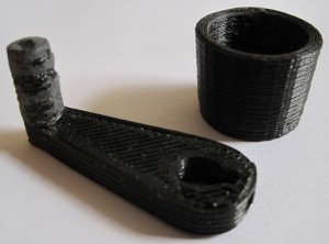
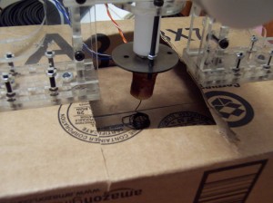
First and second test prints

Well, I’m trying the traditional mini-mug!

Mini-Mug test!

Mini-Mug test!

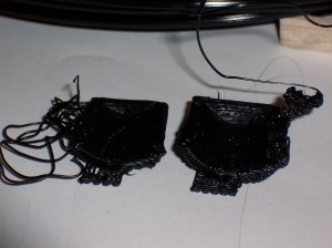
Something tells me they’re not watertight.  The first one (left) snapped off the foam-core raft part way through the build.  The second one (right) got all gloppy and then snapped off the foam core raft part way through the build.

Except for the fact they’re not even close to done, the adhesion between the layers seems pretty good.  The raft on the second one was a little gloppy which caused me to be a little apprehensive throughout the build.  After a few layers the gloppiness evened out.  However, it cropped up again, accumulated, got super gloppy, and ruined the build.

Suggestions?

Building a robot that builds things

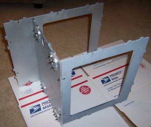
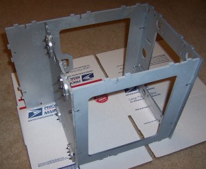
Once the painted parts were dry, I couldn’t resist getting started bolting the thing together.  Putting the parts together is pretty fun – it goes quickly and all the parts fit together very well.  In fact, it went so quickly that I didn’t get pictures of each step as I was originally planning.  Oh well, I guess you’ll just have to build one for yourself.  ;)

Behold!  A robot being born!

Front, middle, back, and Z-axis brackets bolted on

Front, middle, back, and Z-axis brackets bolted on

And now…

The top

The top

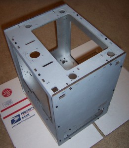
Here the body panels are mostly all put together.  You’ll notice I opted to install the Z-axis threaded rods after assembling the body.

Sides, top, bottom all bolted together

Sides, top, bottom all bolted together

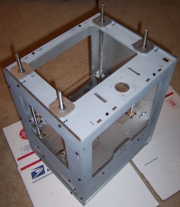
The new system is really huge improvement over the prior.  Before you had to get all of the Z-axis rods identically assembled and installed.  Now I just had to set them up, drop them in, make sure the top of the topmost pulley on each rod was just below the level of the top panel.  Any higher and it would have interfered with the smooth rotation of that axis.

Z-axis installed

Z-axis installed

The Z-stage is also a huge improvement over prior designs.  Since the new brackets are “U” shaped, you can remove the entire stage without having to unbolt the entire assembly.  It’s also possible to adjust one or more rods individually by lifting the stage on that side slightly and rotating the hex nut as required.

I feel smarter just having seen these designs in action.

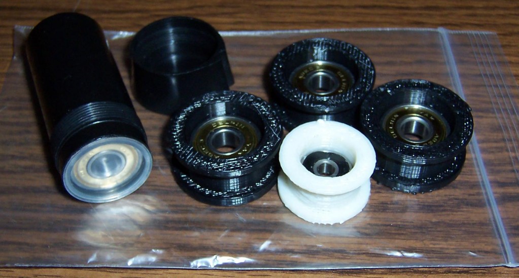
Printed Pulleys Assembled!

I’ve just take the first step to building my MakerBot!  Admittedly, two of the bearings were already in the printed pulleys, but that’s just not the point.  I’ve taken a material step towards building it!  Huzzah!

Printed pulleys assembled!

Printed pulleys assembled!

Oh, and I don’t think I was supposed to have a pack of 8 extra bearings.

No, no, I’m supposed to have these 8 bearings.  I suppose it would help if I read the directions.  (I’m just so used to grabbing things and tossing them together and expecting them to work.  I guess it’s a little more complicated than that when you’re building a robot, eh?)

Soldering?

I have NO idea what I’m doing!

If you’ve got a Batch IX MakerBot all the surface mount boards should have arrived pre-soldered.  This means the first actual material step to building the robot is to solder the opto-endstops.  These are little circuit boards that contain optical switches that will prevent the machine from moving the build platform (and print head?) too far in a particular direction.  You can find the kits for the opto-endstops in the MakerBot store.  According to the page for these kits:

An optical switch usually used to detect when your robot has reached the minimum or maximum position of travel.

An optical endstop AKA opto endstop is a switch made out of light. When something interrupts the light-beam, then it signals the motherboard. Useful for detecting if your robot is attempting to self-destruct. ;)

Also, there are no moving parts to wear out, so they will last pretty much forever.

So, when all is said and done, hopefully I will have taken this:

OptoEndstops Parts

OptoEndstops Parts

To this:

OptoEndstops v2.1

OptoEndstops v2.1