What would you charge?

I know some people use their MakerBots as small scale rapid prototyping services.  What I don’t know is what or how they charge for providing these services.  Obviously, there’s a cost associated with the plastic, electricity, wear and tear, failed prints, etc. 1 Setting aside the intrinsic value of what you have produced 2 , what’s a reasonable way to set the price of an object printed on a MakerBot?

I can think of several ways to look at this:

  • Resource cost. $0.04 per cubic centimeter, of pure cost in terms of just MakerBot ABS/PLA.  Electricity is probably around $0.02 per hour of print time.  The laptop connected to the MakerBot is capable of multitasking, so there’s no real opportunity cost there.
  • Shapeways. Their gray ABS is $2.50/cc.  They also have a white nylon polymide for $1.50/cc with a $1.50 start up charge.  Their colored prints are made with a plastic powder that is relatively fragile.  At $2.50/cc and assuming it takes 4.5 minutes to print 1cc, this comes to $0.56/minute.3
  • Ponoko. Their UV curable resin is $2.76/cc and their white nylon polymide is $0.80/cc. 4 Their colored prints are made with a plastic powder that is relatively fragile.  At a MakerBot’s printing speed, $2.76/cc comes to $0.61/minute.
  • Metrix:Create. They charge $0.50 per actual minute of build time.  However, Metrix:Create members get 20% discounts and anything printed from Thingiverse gets a 20% discount.  Without any associated discounts and assuming we print at the same speed, this comes to $2.25/cc.

I believe transparency makes for a better customer experience.  That way a customer can see right up front what they may be spending, avoiding “sticker shock.”  It is probably a lot easier for the average customer to estimate the volume of a digital design than it is for them to guesstimate how long my printer would take to print such a thing.

What metric and pricing structure do you use to charge for your printing services?  Do you go by volume, weight, plastic used, machine time, or something else entirely?

  1. It takes about 4.5 minutes to print one cubic centimeter of ABS or PLA.  This is a rough average of several different types of settings, but assumes a roughly 0.36mm layer thickness. []
  2. Pretending 19cc of a puzzle cube is worth exactly 19cc of a toy rocket, window latch, or plastic part that will fix the international space station. []
  3. This is more of an analogy to a MakerBot’s printing speed than an actual assumption of the printing capabilities at Shapeways. []
  4. There are discounts for their “prime” members. []

Open Source Printable Building Blocks FTW!

A few weeks ago I posted my criteria for an interlocking  building block system:

  1. The interlocking system should allow interconnections in three dimensions.
  2. The pieces should snap/interlock together reasonably well/easily.
  3. The pieces should stay assembled reasonably well.
  4. The pieces should snap apart reasonably well/easily.
  5. The pieces should not require additional tools to be assembled and disassembled.

Well, just yesterday r3becca of Robots and Dinosaurs posted designs for “Beco Blocks” on Thingiverse.  From the looks of things these Beco Blocks fit every criteria!  I can’t wait to print up a bunch!

Things I learned while soldering opto-endstops

The opto-endstops marked the very first parts I had to solder for this MakerBot.  Not having soldering anything more complicated than two wires together, this was an adventure and learning experience.  Here’s what I learned today:

  • The 3-pin connectors used for two of the opto-endstops (on the Y-axis stage) are in the Generation 3 MakerBot Electronics Kit (Mostly Assembled) with some of the other connector bits.  I was a little confused about this for a while.
  • It helps to lay out all the little bits in an organized fashion beforehand.
  • Keep a long thin rigid stick handy for bending delicate leads into the circuit board holes.
  • Although I read the RepRap electronics fabrication guide and found it helpful, I still felt a little lost.  I found the most effective way to solder the parts in was to:
    • Get the soldering iron good and hot
    • Put the leads through the holes
    • Bend the leads a little so that they stayed in place
    • Flipped the board over so the leads were sticking up
    • Touched the solder to where I wanted the joint
    • Gently stroked the solder with the soldering iron tip towards the joint
    • This process seemed to create a pretty good joint
  • You’re going to burn a finger at some point, accept it.1
  • This almost goes without saying, but go slowly.
  • Check and double check the orientation and placements.
  • I found it helpful to take a large sheet of aluminum foil and shape it into a tray.  This helped contain the parts I was working on and was a good way to catch the flying leads that I clipped off.
  1. I burned two. []

Things I learned while assembling my MakerBot

I’ve assembled quite a lot of my MakerBot today.  This entailed assembling and putting together the X axis stage, Y axis stage, pulleys, putting gears on stepper motors, mounting gears, putting in the slider rods, Z axis threaded rods, bolting on the motors, and assembling the two “dinos.”

  • If you’ve got a Batch 9 MakerBot, definitely install the Z-axis after assembling the body of the MakerBot.
  • Put off adding the Z-stage/extruder-stage for as long as you can.  It will just be in the way.
  • Keep that sandpaper handy – you may need to sand down some tabs or widen slots or holes to make things fit, especially if you painted your MakerBot.
  • If the smooth slider rods are just a smidge too short, they will slide back and forth causing a little extra noise as your MakerBot operates.  I haven’t gotten mine running yet, but I have read this is the case.  I noticed that one of the slider rods for the X axis on my Batch 9 MakerBot was about 1mm too short.  When I put the caps on, I noticed that it still had some wiggle room.  I took a scrap of paper towel, folded it up so that it would push up against the end of the rod, and clamped it down.  There’s no wiggle room now, so hopefully that’s it.
  • Make sure the top bearing is just under the top edge of the top panel.  This is in the directions, but it’s really important to make sure everything spins freely.
  • Putting gears on the stepper motors is tough!  Even when you back the tightening screws on the gears out as much as you can, the fit is incredibly snug.  I eventually sanded the inside of the gear slightly, put the motor on cardboard, and then pushing downwards slowly and forcefully.
  • When you’re installing the geared belts, get them as level as you can manage.
    • For the top stage this will involve adding/subtracting washers/nuts from the printed pulleys as well as adjusting the gear’s placement on the stepper motor.
    • For the X and Y stages, the height would essentially be dictated by the height of the belt on the clamps.  The height of the belt on the clamp is essentially set, so the pulleys and gear on the stepper need to be matched to that.
  • When assembling the carriages with the plastic sliders, the instructions suggest you may need to sand the circular hole they fit into.  Just make a point of sanding them, if they’re tight they could affect the looseness of the stage on the rods.
  • Inspect your Y-stage pulley (this is the smallest printed pulley) to make sure the top is level and there are no protuberances.  Even a little bit of a nub will prevent it from rotating properly.
  • The easiest way to remove the itty-bitty sticky-paper protective acrylic cover is to use a razor blade or exacto-knife to pop them off.  You probably don’t need to, but it’s an aesthetic thing.

Additional parts and tools required for Deluxe kit

Although I have the CupCake CNC Deluxe kit, there are still some parts and tools required.  If you’re getting ready to build your own MakerBot, here’s what else you’d need to build everything in one go:

  • Primer, paint, masks, cardboard, duct tape, and pen – if you’re painting.  While the other stuff is obvious, I found the pen handy for labeling the cardboard next to the parts that had to be painted differently from other nearby parts.
  • Sandpaper for sanding down punch-out-nubs and leveling off plastic parts so they’ll fit.  Based upon my enormous background in robot building, I’d recommend a super fine sandpaper for the nubby bits wooden bits and a medium course sandpaper for sanding down plastic parts.  You won’t need much, so there’s no need to buy a whole pack.  You may also need the course sandpaper for widening the openings for the plastic sliders on the X and Y axis platforms and/or to make some of the tabs fit better if you’ve painted.
  • 3-in-1 oil is needed for the various slides/rods and as part of the cleaning of the Z-axis threaded rods.
  • Paper towels are just a good thing to have around.  Damp they’ll help you wipe down a little bit of the fine ash left by the lasercutter.
  • Electrical tape and an electric drill along with paper towels and 3-in-1 oil are used for the recommended method for cleaning the threaded rods.
  • Zip ties for organizing cables.  But, seriously, you should just have these necessities anyhow.  They’re good for everything.  If you’re going out for zip ties, I’d highly recommend picking up (1) an assortment of colors/sizes in a large pack (2) a pack of uniformly colored small zip ties and (3) a pack of uniformly colored large zip ties.
  • Hot glue gun, hot glue sticks are needed for affixing the plastic sliders on the X and Y axis stages.  Like zip ties, if you have these around you’re going to find they’re a good solution for a lot of problems.  It’s like Windex that way.
  • Popsicle sticks and black paint are needed for completing and installing the opto-endstops.
  • An exacto-knife or razor blade will come in very handy for removing the very very tiny bits of protective cover on the acrylic lasercut parts.
  • Super glue is needed for affixing a pulley to the idler pulley and for laminating some parts of the two “dinos.”

Stopping for now

The body of the MakerBot is complete, rods in, X and Y stages in, pulleys and belts on, motors bolted on.  No opto-ends stops yet for obvious reasons.  The opto-endstops also require popsicle sticks.

On to the plastruder.  I put together the Weird Dino and the Tall Dino, but the idler pulley requires super glue.  I don’t happen to have any lying around, so I’ll need to go out to the hardware store.  But, this is as good a spot to stop as any.

I originally intended to document each step – but the directions on the MakerBot wiki are so good that there’s just no need.  So, the pictures you’re going to see are going to basically jump from a bunch of spraypainted wood giant chunks of the robot already bolted together.

The build process, much of what consists of fitting pieces together and using the MakerBot “t-slot” semi-captive nut method, is very intuitive, relatively easy, and extremely gratifying.  Sometimes its a little bit of effort to get that nut in the notch properly, but it was never that bad.

Building a robot that builds things

Once the painted parts were dry, I couldn’t resist getting started bolting the thing together.  Putting the parts together is pretty fun – it goes quickly and all the parts fit together very well.  In fact, it went so quickly that I didn’t get pictures of each step as I was originally planning.  Oh well, I guess you’ll just have to build one for yourself.  ;)

Behold!  A robot being born!

Front, middle, back, and Z-axis brackets bolted on

Front, middle, back, and Z-axis brackets bolted on

And now…

The top

The top

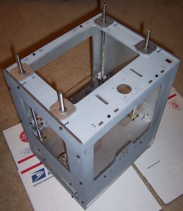
Here the body panels are mostly all put together.  You’ll notice I opted to install the Z-axis threaded rods after assembling the body.

Sides, top, bottom all bolted together

Sides, top, bottom all bolted together

The new system is really huge improvement over the prior.  Before you had to get all of the Z-axis rods identically assembled and installed.  Now I just had to set them up, drop them in, make sure the top of the topmost pulley on each rod was just below the level of the top panel.  Any higher and it would have interfered with the smooth rotation of that axis.

Z-axis installed

Z-axis installed

The Z-stage is also a huge improvement over prior designs.  Since the new brackets are “U” shaped, you can remove the entire stage without having to unbolt the entire assembly.  It’s also possible to adjust one or more rods individually by lifting the stage on that side slightly and rotating the hex nut as required.

I feel smarter just having seen these designs in action.

Things I learned while painting my MakerBot

Painted my MakerBot lasercut wood parts (and plastic pulleys!) today.  Here’s what I learned:

  • Spray paint cans work better when they’re not pointed downwards, so it helps to angle/elevate one part of the painting surface. 1
  • Too much ventilation or cross ventilation will let debris fly into the room.
  • Position the things to be painted close together, it will help you paint faster and will waste less paint.
  • Use primer and buy two cans.  Although, had I positioned the pieces more effectively I may not have needed the second can.  Then again, I think it probably would have worked better to put even more primer than I did.
  • I wiped the edges of some of the smaller parts, but not all of them.  The end result is that some paint wiped off as it had adhered to the ash from the lasercutter.  I think I like this effect as it made the parts look a little worn, but you may not.
  • If you’re painting your MakerBot, don’t forget to consider painting the pulleys!
  • Sand down any stray plastic parts off of the printed pulleys before you paint them.  I didn’t realize the clearance on the small pulley was so low, and I had to sand the painted finish to get it to fit properly.
  • Make sure no parts accidentally shift and overlap before you start painting.  It won’t be a big deal, but it’s a little extra unnecessary work to paint it.
  • If you’re spraypainting different colors, cover other parts while you paint a new color.  A fine mist will be deposited on those other parts.  I like the effect, but it may not work for you.
  • Keep in mind that if you are using a primer and then a coat of paint some of the parts won’t fit as well (or may fit better!) when you go to assemble the robot.  I found it necessary to sand away nearly all of the paint on a few body panel tabs.  I also needed to sand away the pain that got on the inside of the round X and Y axis mount holes.
  • If you’re painting the “MakerBot Industries” logo on the front a different color than the surrounding body, you probably want to do it at this stage.  I didn’t even think about it until I started assembling the body.  It won’t be a problem to paint it by hand later, but I could have done this all at once.
  1. I guess this is why you see graffiti on walls, not floors. []

Here we go!

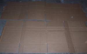
Laying out cardboard on the garage floor.

Spreading out cardboard boxes

Spreading out cardboard boxes

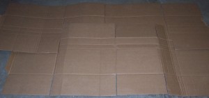
Interweaving layers of cardboard using their flaps.

Interweaving layers of cardboard

Interweaving layers of cardboard

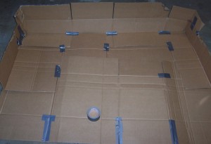
Duct tape layers together, taped shallow sides, duct tape over holes in layers.

Taping up cardboard sheets

Taping up cardboard sheets

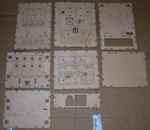
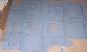
All the wood parts laid out together.  This is just so you can see all the wooden parts at once – they probably wouldn’t paint very evenly this way.  Plus, since I’m painting different parts different colors, I needed to separate them out.

All the wooden bits

All the wooden bits

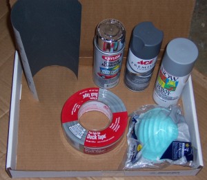
The supplies I picked up from the hardware store.  Super fine sandpaper, metallic spraypaint, medium gray primer, light gray spraypaint, masks, and duct tape. 1

Supplies

Supplies

Well, I just started spraypainting parts!  Now it’s too late to turn back!

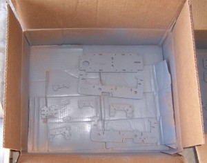
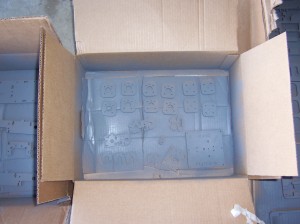
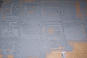
Medium gray primer:

X-platform parts

X-platform parts

Y-platform parts and other bits

Y-platform parts and other bits

Robot body parts everywhere - the horror!

Robot body parts everywhere - the horror!

I couldn’t resist painting the printed pulleys too. There was a lot of interesting variation between the four pulleys. I could also see how one person’s MakerBot had probably been more finely tuned, how another person used a version of the pulleys with fewer facets. The smaller pulley had a little bit of plastic on top of the pulley. I didn’t think anything of it at the time I was painting. However, as it turns out that plastic nub later prevented the pulley from rotating on the Y-stage, so I had to sand it off – ruining the paint job. Once I’ve got the ‘bot printing happily I’ll go back and touch it up.

Printed pulleys - as they were meant to be

Printed pulleys - as they were meant to be seen

Once the primer had dried, I started spraypainting the parts the colors I wanted them to be.

My eyes!  They burn!  These goggles do nothing!

My eyes! They burn! The goggles do nothing!

Painted body parts

Painted body parts

You may notice that I was also painting the leftover parts from which the smaller parts had been punched out.  I did this so I could test the effect of the primer and layers of color.  Without the primer the wood soaked up a lot of the paint, hence the need for the primer.

While painting with the metallic paint a sparse fine mist covered the other parts as well.  I found I really liked the effect of very tiny sliver specks over the flat gray.  If this is something you’re looking to avoid I’d recommend not only spraypainting farther apart, but also covering the other parts you don’t want affected.

  1. I already have duct tape, but it never hurts to have more… []

Sanding

This part is probably unnecessary.  I’m not sanding down the surface of the wood parts because it is so thin the veneer would probably come right off.

However, there are some small tabs throughout the pieces where they were once attached to larger parts.  I’d rather do it now than after painting and then have to paint the sanded parts over again.