Sonic Screwdriver progress

Printable screwdriver

Printable screwdriver

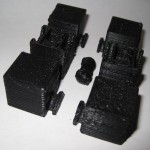
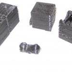
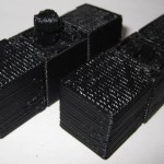
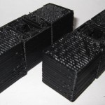
I just redesigned the printable screwdriver in order to make the parts fit together better and be more printable.

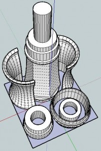
It should be easier to see how these parts go together.

Basically, you take the “mid-handle” at the far end of the build sheet, turn it upside right, clamp the two “lower handle” pieces on either side of it, and slide that bottom ring onto the lower handle.

I still need to redesign the upper handle, hollow out the mid-handle, and make sure there’s enough room inside for the GoodFET / electronic sonic screwdriver guts.

Now I’m wondering if it is also possible to make this a piece of MakerBot origami – and make it printable on one build sheet…

Real life sonic screwdriver

This morning I received an e-mail from Bre out of the blue introducing me to Travis Goodspeed.  Apparently Travis has been working on building sonic screwdriver guts out of the GoodFET, a universal JTAG programmer, a “sonic screwdriver of hacking.”  Travis suggested a GoodFET could be programmed to act as a TV-B-Gone, light show, or any number of other things.  Given that his circuit board is about 3″ x 0.85″ x 0.2″1 , there shouldn’t be a problem finding space for it in the sonic screwdriver I’m in the middle of designing2

Freaking sweet.

So, here’s my real life sonic screwdriver wishlist:

  • Lights.  Red LED3 , white LED4 , green LED5 , and a UV LED6
  • An actual screwdriver bit or spot where you can attach a screwdriver bit.  It would just be cool to have a sonic screwdriver that could be used as a screwdriver.
  • A shakey Tic-Tac container style recharger.  Having a sonic screwdriver that doesn’t need batteries would be awesome.
  • A tiny speaker that played the sonic screwdriver sound.
  • A tiny magnet.  I remember watching Doctor Who back in the day, black and white old school episodes, where he used his sonic screwdriver to take screws out of things, bolts out of doors, etc in the worst stop motion animation the BBC could get away with.  Still, if this sonic screwdriver had a magnet, it could actually affect a physical change via magnetic force.
  • TV-B-Gone.  On the episode “Midnight” Doctor Who shuts off a bunch of TV’s using his sonic screwdriver.  This would be an INCREDIBLE feature!
  • Flash drive and/or mini-memory card reader.  Perhaps with the entire library from PortableApps.com installed.
  1. For those of you non-imperialists out there: 76.2mm x 21.59mm x 5.08mm []
  2. TBuser, if you want to help, lemme know! []
  3. For night vision.  Also, there are suggestions that a sonic screwdriver can have a “red setting.” []
  4. As a flashlight. []
  5. The 11th Doctor’s screwdriver has a green light. []
  6. For making things fluoresce such as secret messages, blood stains, and monsters. []

MakerBot Origami

1. Or, “Design Constraints and Creativity”

Origami is another of my hobbies and it is all about design constraints. 1 The rules are simple2 – one square sheet of paper only manipulated by folding. 3  Yet, within these rules it is theorized that a sufficiently skilled artisan can design and fold any arbitrary figure.  I find folding origami to be at once cathartic and contemplative. 4

Pondering the design constraints within origami reminded me of one of my own recent designs – the 3x2x1 Rubik’s style puzzle cube.  Quite apart from the medium or subject matter, I really liked the idea of a single print job resulting in parts that could be immediately hand-assembled without tools to form a useful object.  Then I thought – if the design constraints are one of the things I like about this design, what else is possible within these same constraints?

Thus, I propose a new style of “MakerBot Origami”:  One MakerBot print5 , multiple components6 , no tools or hardware7 .

What’s the coolest most awesome thing you can design within these constraints?

Update:  Cyrozap – sory fore mispellnig yoru mane.

((I waffled on that title.))
  1. I waffled on that title. []
  2. Modern origami rules, anyhow. []
  3. Designing an origami model is not about figuring a way to cheat those rules – rather a way to work within them to achieve a desired goal. []
  4. I recall one origami master referring to the folding of a particularly difficult and rewarding model as invigorating. []
  5. Or, as Cryozap Cyrozap calls them, “production file.” []
  6. Otherwise, people would be making whistles. []
  7. Thus, no bottle openers []

Printable Sonic Screwdriver progress

STL sheet for printable sonic screwdriver

STL sheet for printable sonic screwdriver

Sketch of Screwdriver

Sketch of Screwdriver

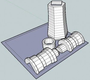
Off to the left is a picture of what the finished sonic screwdriver should look like.  Here’s a picture of the parts I’ve designed so far.  Assembled properly, these parts should be able to be assembled into the lower half of the sonic screwdriver.

I’ve arranged the parts so that they have a less than 60mm x 60mm footprint on the build platform.  I would really like it if the final product could be printed all on one build plate and assembled without tools or additional non-printed pieces.

After my recent design-print fail, I’m going back to the drawing board (slightly)1 wiser.  If nothing else, I like to think what I have so far is pretty neat. 2

  1. Make that very slightly. []
  2. Even if it doesn’t work at all. []

Design-print fail

I’ve been slowly working on the design of a printable (and fully MakerBottable) sonic screwdriver.  This model of the sonic screwdriver is built up of a number of concentric cylinders, has several significant overhangs well in excess of 45 degrees, and is larger than the MakerBot’s built capacity.  In order to deal with these design problems, I modeled it in sections.

In order to make the overall result something I could just pop/snap/slide together I designed it making some sections which were split vertically and other sections which slide around those sections to keep them together.  In order to make the parts quickly printable I designed all the parts at around 0.5mm thickness.

About 40% of the way through the print one of the vertical sections wasn’t coming out properly – probably because it was too thin.  The parts were too thin and flexible and ended up tearing between layers and just being too flimsy.

I also noticed something odd – the extrusion was too thin on that side of the model.   I can’t be sure why this is happening – but I suspect it’s due to the extruder not getting a good enough grip.  Perhaps I need to floss the extruder pulley or install a new extruder idler wheel.  However, it doesn’t explain why the extrusion was too thin on just that one side and no other spots.

Suggestions?

3x2x1 Rubik’s Cube Production File

My prior copy of this 3x2x1 Rubik’s Cube was printed a few parts at a time – I’d print one part, test it, print up another, etc.  Last night I was able to use my production file to generate all seven pieces in one go.  It took 1 hour and 45 minutes to complete the print job, but well under three minutes to clear most of the pieces of the raft off the parts and assemble the puzzle.  In order to help people modify and improve upon my design, I’ve upload the original Sketchup files, the STL I used, as well as my own GCode.

Owenscenic on Thingiverse asked,

I am interested in trying your gcode, how did you generate it? How well does it minimize strings between the printed parts? I’ll look at is to see how it starts and the temp…

In case you’re wondering too, the answers are as follows:

  1. I generated the Gcode using my slightly tweaked RepG v18 built-in Skeinforge settings for ABS with a raft, with a build temperature of 220C.
  2. The Gcode does pretty well with minimizing stringing.  However, some of the credit has to go with the part placement in the STL production file as well as the nature of the object.  As soon as you assemble it and start to rotate the parts, most of the remaining strings and little blobbies will pop right off.

Owenscenic, please let me know how your print of this turned out!  Please post a picture!

3x2x1 Rubik’s Cube assembly pictures

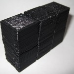
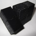
The design should be pretty intuitive.  However, I went ahead and took some pictures of the assembly anyhow.

As I mentioned in an earlier post, I think this one came out really really well.  :)

Tyvek Sled Kite… from office supplies

Tyvek Office Supply Kite

The picture to the right is of a kite that I built several weeks ago and only got around to actually flying this weekend.  It’s basically made out of office supplies.  :)

Originally I just wanted to make the Tyvek sled kite from the Howtoons shown in Craft Magazine, Volume 81  But then I wanted to see how much of the kite I could assemble just using things from the office.  The answer is, basically all of it.

The Howtoons calls for:

  1. A large sheet of Tyvek
  2. Tyvek tape
  3. A washer
  4. Ruler
  5. Scissors

Instead I used:

  1. Tyvek from Tyvek office envelopes, rather than a large sheet or roll of Tyvek house wrap.  My office is sent dozens of these things a day.  It didn’t take long to collect 30 plus.
  2. Clear packing tape.  I used this instead of Tyvek tape.  Tyvek tape would have worked a LOT better, but I have no complaints.
  3. Rather than use a washer, I used a spare keyring.  I had other various office supply bits hanging around in case this didn’t work out.  Paperclips, binder clips, etc.
  4. Yardstick.
  5. Scissors.

Since the envelopes are significantly smaller than the sheet of Tyvek rolls, I had to either make my kite smaller or stitch them together into a larger sheet.  I did both.  I scaled the plans down to about 2/3rds the size from the diagrams and then used packing tape to put them all together.  To get the most surface area out of each envelope, I burst all of the envelopes at the seams and then taped them up.  Once I had a 36″ tall sheet, I started cutting it into the pieces I needed, re-taped it back together as indicated by the diagram, and then set it aside for weeks while I didn’t fly it.  :)

On the day of the launch I made the tail out of strips of leftover envelopes taped together with the gluey bits from some of the envelope flap sealants and more packing tape.  I punched a hole in the three ribs using a pen, ran the line through each of the three ribs, reinforced it with more packing tape…  and launched.

The only non-office supply things used in the construction were:

  • Crayons for coloring the kite (hard to see)
  • The ruler – I don’t have a yardstick at work
  • The kite line, purchased from Amazon

It flew pretty well.

  1. I found a copy of all three pages after googling around a little.  Howtoons: Sled on a Thread pages 1 2, 3 []

3x2x1 Rubik’s Cube – done!

I’m so happy with the way this has turned out.

I’ve made a bunch of changes since the last revision of this printable 3x2x1 Rubik’s Cube puzzle:

  • I’ve totally redesigned the center barbell connector.  I simplified the design, removed the five support struts for each end and replaced it with a single support strut and a flat hexagon in the center of the piece.  The purpose of the hexagon is to give the barbell more contact area with the raft.  One of the earlier drafts didn’t have as many supports or this flat hexagon, and it tore off the build platform partway through the build.
  • I increased the diameter of the tube between the barbells.  This enabled it to print easier, made it a little more sturdy, and decreased the wobbliness of the barbell when everything is assembled.
  • I also shortened the entire barbell by 1mm, so that the entire puzzle is held together more closely.
  • I made the flat semi-circular tabs slightly thinner so they rotate a little more freely.
  • I significantly redesigned, thickened and simplified the two brackets that the barbell snaps into.  It’s been able to easily withstand numerous couplings/decouplings as well as numerous rotations.  With a few rotations, all parts now rotate easily.
  • All of the parts fit together SO much better than my first draft held together with a nut and bolt.
  • There is a slight bit of sideways flex that can occur with the use of the barbell.  It is really minor and it actually seems to help the puzzle be more forgiving as you manipulate it.  I see this more as a benefit than a design flaw.

The was one design choice on which I waffled.  I considered making the center cubes non-identical, with one having half a barbell stick out and with the other having the internal connector you see now.  This would have removed much of the sideways flex – since the barbell would be stationary.  I did not go with this design choice because whether the puzzle used one barbell and two connectors or male/female center cubes, there would always be some flex caused by the use of a connector rather than a static pin.  And, to be honest, I much preferred the symmetry of having everything assembled out of just three unique parts.

I know I’ve mentioned this before, but I really like the idea of a MakerBot printable toy that can be printed in one go and then assembled without tools or any additional hardware.  I also think this would make a great MakerBot print demonstration.

I’ll post some pictures of the parts a little bit later.