RepG – the best one of them all

Adam, if you read this – the latest RepG is AMAZING.  Getting to preview an STL, convert to GCode, and then to an S3G file all from the comfort of the friendly RepG UI is fantastic!

It’s not that I’m scared of the Skeinforge UI or anything.

It’s just that it stalks me while I sleep, steals my happy innocent dreams, and replaces them with a theater of shadow puppet parade of horrors.

Skeinforge UI suggestions

I rather enjoy building the easy-to-use user interfaces for another website of mine.  I’m always tweaking it and trying to make it better.  Small change, test, ask for input, LRR.1

My last post gave me a great idea.  A large physical console with actual knobs, switches, and dials that all operate Skeinforge.  If I had one of these, I would want it to look like the center console of a TARDIS.  Some of the best Doctor Who moments are when he’s zipping around the console, tapping, flipping, twisting, turning and generally being wacky.

Imagine being able to do that sort of thing and then have a plastic object (of a seemingly correspondingly random quality) pop out of the center?

  1. Lather, rinse, repeat. []

Patience

As MakerBots and RepRaps proliferate, so do the websites and content concerning them.  Gian Pablo Villamil had a really great post about his adventures with Skeinforge.  As with BotHacker’s excellent post about the Skeinforge Cool setting and analysis about the benefits of cooling fans, Gian’s post takes us through each of his Skeinforge changes as well as documenting it’s effect on the print quality.

I wish I had more patience for that.  I tried for a while documenting each change…  but quickly became enamored with the idea of spinning dials and flipping switches in Skeinforge in the (sadly badly) mistaken belief I could make it better.

Documenting Skeinforge settings

Uncool tower, cool tower

Uncool tower, cool tower

BotHacker recently documented his adventures in cooling fans and Skeinforge options – to amazing effect. 1  You should read the entire post, because there’s a lot of good info in there.  However, to summarize:

  1. Numerous permutations of cooling fan sizes and speeds offered some improvement.
  2. Using no cooling fans and putting the Skeinforge Cool setting at a minimum layer time of 10 seconds offered a dramatic improvement.

BotHacker’s post is what Skeinforge documentation should look like.

Update: Per BotHacker’s comment below, “Skeinforge must be told to ‘Slow Down’ for this to work. The other option is ‘Orbit’, and may lead to poorer results.”

  1. BotHacker – your photo to the right on Flickr says “all rights reserved” but I thought you might not mind me discussing your post and photos favorably.  If you don’t want me to link or post a copy of your photo, let me know and I’ll take it down. – MakerBlock []

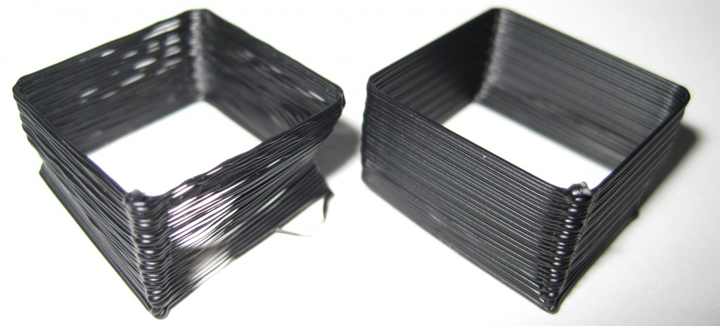
Skeinforge calibration test 1, 2

Test 1, Test 2

Test 1, Test 2

For these tests I used the “single walled test piece” from Da3v

  1. Test 1 on the left
    1. Temperature: 220
    2. Skeinforge -> Carve -> Layer Thickness (mm): 0.36
    3. Skeinforge -> Speed -> Flowrate PWM Setting (if PWM Setting is Chosen): 230
    4. Skeinforge -> Speed -> Feedrate (mm/s): 40
    5. Skeinforge -> Speed -> Travel Feedrate (mm/s): 40
    6. Extrusion diameter: 0.57
    7. Skeinforge -> Speed -> Extrusion Diameter Over Thickness (ratio): 1.583
    8. Wall thickness of the test piece: 0.40
  2. Test 2 on the right
    1. Skeinforge -> Speed -> Feedrate (mm/s): 30
    2. Skeinforge -> Speed -> Travel Feedrate (mm/s): 30
    3. Wall thickness of the test piece: 0.40
    4. Skeinforge -> Speed -> Extrusion Diameter Over Thickness (ratio): 1.583
    5. Skeinforge -> Carve -> Extrusion Width over Thickness (ratio): 1.583
    6. Skeinforge -> Inset -> Extrusion Perimeter Width over Thickness (ratio): 1.583

That’s a pretty big improvement.  I haven’t tried printing something small with lots of details, but now I’m curious how well these settings hold up.  My previous settings (which I zipped in case I totally messed this up) were reasonably good, but the layer adhesion was merely adequate.

How to caliberate and tune Skeinforge for your MakerBot

Update 4/21/2011: This post is more than a year old.  Since then I’ve created ProfileMaker which should eliminate the need for almost all of these steps.  Share and enjoy!


A MakerBot Operators group member, Cliff Biffle, has posted a very comprehensive list his Skeinforge tuning and calibration procedure.  Cliff owns MakerBot #69 from Batch#4, named Kallisti.  Although Cliff has a MakerBot Skeinforge tuning page, it looks like he hasn’t had a chance to transcribe his lab notebook yet.  However, Cliff has been patient enough to type up his Skeinforge calibration information twice for the benefit of the MakerBot Operators group.  Here are links to his original postings on 1/6/2010 and another on 1/15/2010.

The other day I wanted to go back and find his calibration procedure, but had forgotten who had posted it, when it was posted, and which thread it was posted.  Having now found it, I don’t want to lose it again.  It turns out that Cliff had posted it once in response to my own question about dialing in Skeinforge settings in order to print up lego pieces!  Thanks Cliff!

I’ve mashed his two posts together to put together this checklist:

  1. Adjust Temperature:  Skeinforge -> Raft
    1. Find a temperature that allows you to extrude quickly and easily without too much popping or smoking
    2. MakerBlock: I have one of the 1mm thermistors, use the Zach 1 temperature table, and print reliably at 220
  2. Adjust Layer Height: Skeinforge -> Carve -> Layer Thickness (mm)
    1. Cliff uses the default of 0.36
  3. Adjust Extrusion Speed: Skeinforge -> Speed -> Flowrate PWM Setting (if PWM Setting is Chosen)
    1. Make the extruder go slower and lower the PWM value
    2. Cliff uses 230
  4. Adjust Feedrate: Skeinforge -> Speed -> Feedrate (mm/s)
    1. Too fast and you lose the fine detail and introduce errors.  Too slow and it will be too… slow.
  5. Adjust Skeinforge to understand how much plastic is being extruded
    1. Raise the Z axis and perform a test extrusion into the air
    2. Do not pull or stretch the extrusion
    3. Using calipers, measure its diameter, D
    4. Go into Skeinforge and look up the configured layer thickness, T, from Skeinforge -> Carve -> Layer Thickness (mm)
    5. Divide the diameter by the thickness, D/T
    6. Set Skeinforge -> Speed -> Extrusion Diameter Over Thickness (ratio) to D/T
    7. Print a test piece with thin walls
    8. Measure the width, W, of a single extrusion somewhere above the first few layers
    9. Divide the width by the thickness, W/T
    10. Set Skeinforge -> Carve -> Extrusion Width Over Thickness (ratio) to W/T
      • Cliff said this setting may be in Fill, but I think he may have meant Carve

    11. Nick Ames has suggested setting Skeinforge -> Carve –> Extrusion Width over Thickness (ratio), Skeinforge -> Inset -> Extrusion Perimeter Width over Thickness (ratio), and Skeinforge -> Speed -> Extrusion Diameter over Thickness (ratio) all to the same value.  His post also has a lot of information and links about other potential Skeinforge tuning resources.
  6. Adjust other Skeinforge settings
    1. Overlap of grid corners
    2. Infill density
    3. Unpause
    4. Stretch

New print: TARDIS

InnovationByLayers – you rule.  Thank you for modeling and posting this.  I’ve really wanted to print out a TARDIS and a Dalek.  I downloaded the file, ran it through Skeinforge, and started printing away.

1 hour and 8 minutes later:

TARDIS

TARDIS

I am very happy with this print.  You can see some very minor vertical variation in the model, which is quite exaggerated by the photographic angle, but it’s probably about 0.33mm or so.  The variation is barely noticeable.   I suspect I could get better resolution if all four of my Z axis threaded rods were straighter, but I also think my time/effort is probably better spent dialing into the correct Skeinforge settings.