
The design should be pretty intuitive. However, I went ahead and took some pictures of the assembly anyhow.
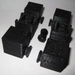
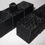
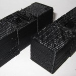
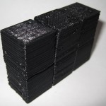
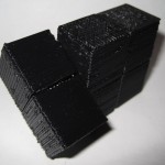
As I mentioned in an earlier post, I think this one came out really really well. :)
Design tips for creating 3D digital models for printing on a MakerBot
The design should be pretty intuitive. However, I went ahead and took some pictures of the assembly anyhow.
As I mentioned in an earlier post, I think this one came out really really well. :)

The picture to the right is of a kite that I built several weeks ago and only got around to actually flying this weekend. It’s basically made out of office supplies. :)
Originally I just wanted to make the Tyvek sled kite from the Howtoons shown in Craft Magazine, Volume 8. 1 But then I wanted to see how much of the kite I could assemble just using things from the office. The answer is, basically all of it.
The Howtoons calls for:
Instead I used:
Since the envelopes are significantly smaller than the sheet of Tyvek rolls, I had to either make my kite smaller or stitch them together into a larger sheet. I did both. I scaled the plans down to about 2/3rds the size from the diagrams and then used packing tape to put them all together. To get the most surface area out of each envelope, I burst all of the envelopes at the seams and then taped them up. Once I had a 36″ tall sheet, I started cutting it into the pieces I needed, re-taped it back together as indicated by the diagram, and then set it aside for weeks while I didn’t fly it. :)
On the day of the launch I made the tail out of strips of leftover envelopes taped together with the gluey bits from some of the envelope flap sealants and more packing tape. I punched a hole in the three ribs using a pen, ran the line through each of the three ribs, reinforced it with more packing tape… and launched.
The only non-office supply things used in the construction were:
It flew pretty well.
I’m so happy with the way this has turned out.
I’ve made a bunch of changes since the last revision of this printable 3x2x1 Rubik’s Cube puzzle:
The was one design choice on which I waffled. I considered making the center cubes non-identical, with one having half a barbell stick out and with the other having the internal connector you see now. This would have removed much of the sideways flex – since the barbell would be stationary. I did not go with this design choice because whether the puzzle used one barbell and two connectors or male/female center cubes, there would always be some flex caused by the use of a connector rather than a static pin. And, to be honest, I much preferred the symmetry of having everything assembled out of just three unique parts.
I know I’ve mentioned this before, but I really like the idea of a MakerBot printable toy that can be printed in one go and then assembled without tools or any additional hardware. I also think this would make a great MakerBot print demonstration.
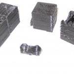
I’ll post some pictures of the parts a little bit later.

This is easily my most intricate digital design for the MakerBot yet. It’s a 3x2x1 variation on the Rubik’s cube puzzle I had posted earlier.
This version incorporates the prior improvements as well as designing a connector system inspired by R3bbeca‘s beco block connectors.
This has enabled a totally printable toy. This just makes me happy. 1 The idea that I can crank out a set of these parts, clean them up a little, and just snap the toy together is just amazing.
TomZ‘s original 1x2x3 “friendlier” Rubik’s cube designs were also totally printable – but required a printed pin that was later glued in place. I like the ideal of all printed parts – but strongly prefer a design that can later be disassembled easily. And, as I mentioned above – the ability to hand assemble the toy is important to me.
I wasn’t able to recreate R3bbeca’s female connector designs2 so I made a simplified version that should suffice.
The simplified connection mechanism is essentially two plastic fingers that will (hopefully) pinch the barbell into place. This was made by designing the outline of the gripping “fingers,” creating a horizontal cylindrical hole slightly larger than the intended end of the barbell, then creating a vertical cylindrical hole in the center for the barbell to be inserted through, then a bit of cleanup.
The biggest potential problem is that this design will require a carefully tuned ‘bot. The center cube pieces have a lot of stuff packed in there – semi-circular slots for the semi-circular tabs, connectors for the barbell, and thin walls separating things. With those thin walls and interior overhangs, this may be a difficult design to print.
I think Bender is up to the task, but we’ll see in a few hours. :) I can’t wait to print this!
For me, having a MakerBot is like waking up to Christmas every morning.
Oh, and before I forget, if you want one of these – leave a comment or send me an e-mail through the Contact page. Make me an offer.
I’ve been fiddling with the designs for the 3x2x1 Rubik’s Cube incorporating some of the changes I had considered:
After playing with this puzzle for a few days I’m really happy with how it turned out and I think the above improvements will make the next version a little bit better. This reminds me of Forrest Higgs’ recent commentary on engineering with a RepRap in the design cycle. It’s so easy to test out a new design that I don’t hesitate to whip something up, print it off, SEE and FEEL how it works and any unintended nuances of that design, and then redesign with these revelations in mind.

Problem: Broken crayons, useless crayon bits, or crayon shavings. Crayola has their own crayon making system – a cross between an easy-bake-oven and little molds. However, I don’t think it is quite versatile enough. Plus, why pay $20 for what could be accomplished easily for $0.20 worth of plastic parts?
Solution: A printed crayon mold!
Description: Crayons melt at about 128 – 147 degrees Fahrenheit, or up to about 66 degrees Celsius. ABS won’t melt until around 88-125 degrees Celsius, so there’s a wide margin for melting the paraffin wax crayons without distorting the mold.1
I would want at least three different molds – the normal crayon size, the fat crayon size, and then a triangular non-rolling crayon size. I’m picturing a two part mold for each, with the seam of the two parts running along the crayon lengthwise and a half funnel for pouring.
In addition to the half-mold, I’d also design a snug fitting square block for fitting the assembled mold into. That way you could stand it up and pour crayon wax into it.
Another potential use for this would be to place the pieces of crayon inside the mold, close it up, then heat. This would allow you to mend a broken crayon.
Usage: I can think of several different ways to use this mold. Frankly, I’m not sure which is easiest/most advisable/least advisable. There are easily several considerations:
I’m not sure which method of heating and cooling are optimal. Though I’d suspect it is preferable to apply the least amount of heat over the shortest period possible.
Variations: It would be interesting to create these molds in different shapes besides cylinders. You could top each one with a geometric shape, the head (or tail!) of some kind of animal or character, or something else entirely. You could mold crayons into spheres, blocks, chips, or little figurines. While not particularly sturdy, you could even mold them into building blocks or components of some larger device. A clever person could use some left over nichrome wire to build a heated metallic funnel.

… or Happy Zombie Day!
My extruder is back online! Huzzah! Since I had it disassembled I made a few minor modifications.
As I tinker and modify my MakerBot it seems I’m moving towards a system where I try to make the extruder assembly as modular as possible. I didn’t have this as a conscious thought when I started, but that’s where these modifications have been headed. While it is very convenient to have a totally modular extruder only connected to the robot by four bolts and an ethernet cable, that system is most useful if you are using drastically different print heads (such as a frostruder, Paxtruder, Bowden extruder, etc).
If you’re just swapping between PLA, ABS, or other plastic filament or color variations thereof, you can reuse the vast majority of the extruder assembly – the board, the motor, and the entire acrylic plastruder. If you had a different heater assembly you could just undo the two screws that attach the heater to the extruder, disconnect the thermistor, disconnect the nichrome, and swap in a new set. Although I don’t have a fully assembled second heater section yet, this set up makes a lot of sense to me just for ease of maintenance and repair.
I’ve already pontificated on the idea that if you’ve purchased a MakerBot Cupcake CNC Deluxe kit, you basically get a second MakerBot for half off. (Spoiler: it’s because you can print a ton of the most expensive parts that go into building a new one). I don’t know why, but the idea of replacing wooden parts on my ‘bot with printed parts just fascinates me. 1
So, let’s have a list of potentially (and actually!) printable parts:
Having more printed components for the MakerBot would reduce a lot of work in it’s assembly. There’s a lot of tiny fiddly bits in the X and Y stages that would become obsolete.
Heck, it might even be possible to replace some of the bolts with some kind of printable fastener system.

Here’s my entry in the Mouse Get! Challenge from Cathal Garvey. I call it the “Peanut Butter Jar Mousetrap Insert.”
The idea is pretty simple. Mice probably like peanut butter enough to squeeze into a small opening for a chance to eat it. If the opening is difficult to wedge back open they might not be able to get back out.
So, buy a jar of peanut butter, eat most of it, leave some peanut butter at the bottom, cut out most of the top from the lid, print the “Peanut Butter Jar Mousetrap Insert“, put the insert with the pointy bits going inside, close the lid, prop it up somewhere so it doesn’t roll away, and wait for your peanut butter covered mouse!