Tony’s recent comment to my post about my alternate extruder controller board mount really deserves its own post. Tony’s comment was:
That’s a pretty logical place for it. Other than needing some more wiring, I wonder why they didn’t design it that way? I wonder if it might introduce some EMI noise?
I’m about 95% sure I know why they designed the extruder mount on the extruder itself rather than the side of the ‘bot. As designed the entire extruder is completely modular. You could swap in a brand new extruder assembly in about 30 seconds (four bolts, one ethernet cable). Heck, if you had a second Z stage and extruder you could probably swap in a new extruder in 15 seconds (one ethernet cable, swap Z stage). They’ve said from the beginning they wanted their system to be totally modular and hackable – and that it is.
I haven’t noticed any symptoms of EMI noise on my prints. In fact, I’m getting some really great prints with my current Skienforge settings. I have a little blobbing and stringing – but I suspect that could be fixed with some attention to oozebane etc.
There are a few really great things about my setup:
- More modularity. A totally new extruder (let’s say dedicated to PLA or a different color ABS) would not require a second extruder board. This means with a printstruder and printed dinos (I’m still refining those designs) you could have a totally modular extruder for about $65 worth of hardware rather than $175 ($125 plastruder kit + $50 extruder controller board).
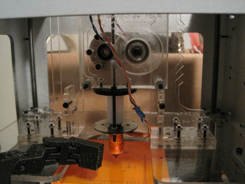
- Visibility. I can easily see what’s going inside the extruder and whether the idler wheel is moving – without lines on the idler wheel.
- Less work. It’s one less thing to take off the extruder when I need to do any kind of work on the extruder. It’s not much time, but it is still a benefit.
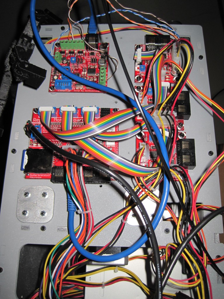
- Ergonomics. My ‘bot is sitting on a surface about 5 feet off the ground. Having the motherboard rotated 90 degrees counter clockwise allows me to front-load the SD card. This is easier for me because of the surface height, but I also had to do it because otherwise the side mounted extruder board would have blocked the SD card slot. Frankly, I would rotate the motherboard even if the extruder isn’t side-mounted.
- Centrality. This keeps all of the electronics all in one spot and makes inter-board cabling slightly easier. 1
- Less movement. I doubt moving the extruder board around on the Z stage would ever cause a problem – but it certainly won’t when it is side-mounted.
However, this setup isn’t perfect:
- Less modularity. One could argue that having the extruder board side-mounted decreases the modularity of the system.
- Counterpoint: That said, if you already have an entire second extruder complete with extruder board, there’s nothing stopping you from swapping it in as easily.
- More wires. I now have six wires2 running to the extruder board. Disconnecting/reconnecting six wires is more work than disconnecting/reconnecting one ethernet cable.
- Counterpoint: In just about any circumstance where you are disassembling your extruder you’re going to need to disconnect those six wires anyhow.
- Counterpoint: I picked up a six pin male/female connecter set the other day. Once I clip the wires I can again have a plug-n-play extruder without needing to fiddle with screw based connectors or with the extruder board in the way.
- More maintenance. Those same six wires need to be maintained/wrangled instead of one ethernet cable.
- Counterpoint: As you can see from the pictures I’m using the little blue twist-ties that came with the ethernet cables to essentially bundle the wires together. I just wind the twist tie around the bundle and compress it to form a tight coil. Works really well with several of these placed at intervals. Clean and still flexible.
- Shielding. There is less shielding on the six thing wires versus one large ethernet cable.
- Counterpoint: This has not been an issue for me.
- EMI noise. I’ve never had problems which I would attribute to EMI noise from wiring, but I suppose it is possible.
- More work. It is slightly more work to put the extra holes in the side of the bot to allow the motherboard to be mounted 90 degrees counter-clockwise and mount the extruder board on the side.
- Counterpoint: Perhaps 5 minutes of work total?
- Z stage blockage. My extruder board is attached by only three bolts because one of them interfered with the Z stage.
- Counterpoint: This just isn’t that much of an issue, especially with the extruder board remaining stationary.
Overall, I find the benefits far outweigh any problems that side-mounting the extruder might cause.
- But, as you can see from the prior post, not much neater. [↩]
- Two each for the thermistor, nichrome, and extruder motor. [↩]


