Tap Light Focus Timer System

I’ve been procrastineering on a “sticky note timer” which would incorporate an e-ink display, be portable, updatable via WiFi, show me what I should be working on, and flash lights at me to give me a sense of movement / time passing / and urgency.  Sometimes I use the word “procrastineering” to refer to when I start to spiral on a project and end up in analysis paralysis.  But, I think it is more appropriately used when I’m doing a deep dive on a project when I really have something much more important / urgent I should be working on.

A long time ago I added a few components to an off the shelf dollar store tap light and turned it into a game buzzer.  While the sticky note timer project was marinating  / incubating1 in the back of my brain, I realized that maybe I don’t need or even want something that high-tech.  Maybe what I need is something dead simple?  As cool as the sticky note timer project is – and it really is neat – there’s a lot of pieces to the puzzle and a fair bit of maintenance that goes along with it once its finished.  You have to connect to it, upload a list, set up timers, etc.

I finally decided on something not so easily adjustable, but still flexible in it’s simplicity.  Rather than making the setup (adding / updating / uploading lists to a timer) something I have to do in order to start the timer, what if I made it part of the timing?

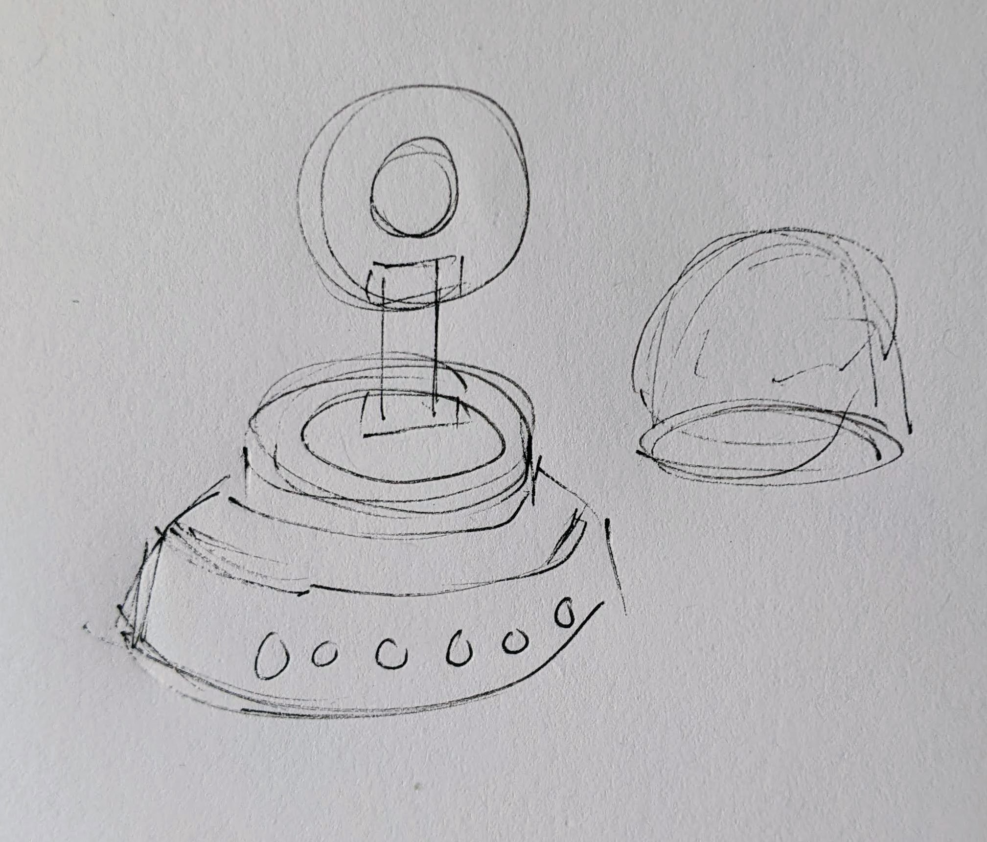
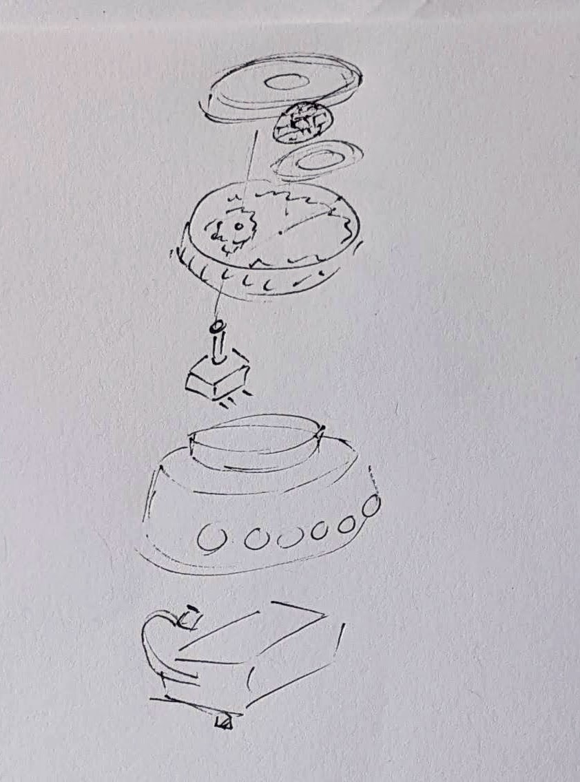
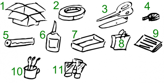
First, let’s look at what the setup.  A dollar store tap light which includes a lot of handy parts – a battery holder, a push button switch, several springs, and a simple and at attractive enclosure.

This slideshow requires JavaScript.

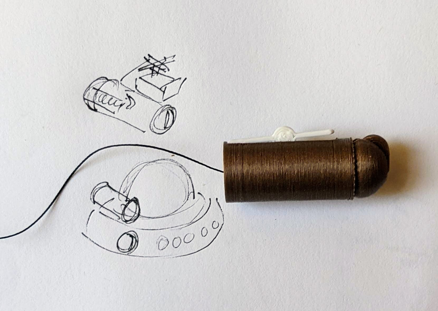
On the far left is a basic off the shelf dollar store tap light.  Next to it are two others I had previously modified to work as game / timer buzzers2  The last picture is the wiring diagram, except that I wired the ATTiny chip to the positive wire coming from the button switch.  Whenever I hit the button, it will toggle the circuit on and off.

Using some parts from my electronics bin3, I cobbled together a prototype on a breadboard that would do the following when the button was hit:

  • Turn orange for 1 minute and beep 3 times in the last 3 seconds
  • Beep once more and turn green for 12 minutes, then fade from yellow through orange over the last 3 minutes
  • Flash red and beep three times after 15 minutes had lapsed (12 minutes of green and 3 minutes of color fading)
  • Turn off, go to a low power mode, and then wake up long enough to flash blue every 8 seconds
  • After 5 minutes, it would flash green and beep twice
  • Then keep doing this 8 second blue flash and green light plus beep every 5 minutes
Animation of LED timer button

You’re probably wondering – what’s with all these timers and lights and beeps?  Here’s how I use them:

  • Place and slap the button to get going
    • I put my phone on my desk and the timer right on top of my phone.  It’s a big 4″ diameter timer and covers the phone pretty well.  I can’t pick up my phone without seeing this timer ticking down.  This is a huge difference between a phone app and a physical thing standing between me and my phone.  There are some web browser based apps – but these don’t really work for me.  Either I have to keep that window open and on top or … I’ll forget it exists.  This timer is right there, front and center, on my desk and lit up no matter where my desktop might take me.
    • Plus, it’s actually a little therapeutic to slap the tap light.  Pushbutton switches like this are built to take a bit of abuse and the physical action of hitting the light is a lot of fun.
  • Orange for 1 minute
    • This is the replacement for the “maintain / update a list.”  Instead of having to fuss with a list, I’ve dumped myself directly into work.  I’m suddenly racing the clock for 60 seconds to write all the things I want to try and accomplish in the next 15 minutes.  Maybe it’s a few emails, make some phone calls, or write / edit a document.  After 57 seconds, the buzzer will beep three times to let me know that the 15 minute timer is about to start.
    • Or, if you already have a particular task to work on, you could use this time to follow a process like Steven Kotler’s suggestions on tactical transitions to a a flow state4.  His three step process is:
      • Anchor your body
        • Practice box breathing.5  You could box breathe 3 times in one minute and have a few second left over to psych yourself up.
      • Focus your mind
        • Write down one clear goal.
      • Trigger your ritual
        • Recite a mantra, perform a gesture, start a “work” playlist
  • Green for 15 minutes
    • It’s go time!  Whatever I wrote down, now I’m in a race to work on those things – and those things only.  I can’t let new emails, calls, etc, distract me – that buzzer is going off in 15 minutes.  As the timer closes in on 15 minutes, with just 3 minutes to go, it turns yellow and fades to orange.  If I look up / down and see this, I know I’m in the home stretch and I’ve got to start moving fast to wrap things up.
  • Red alert!
    • Once the 15 minutes is up the light flashes red and beeps to let me know I’m off the hook.  Now, if I’ve already hit peak productivity, I could keep going.  If I got sidetracked, it’s an alert for me to restart the timer and get back to it.
  • Blue flashes, 5 minute green flash and beeps
    • These blue flashes happen once every 8 seconds6 just to keep the timer present in my vision so it doesn’t just appear into the mess on my desk.
    • If I finished out the 15 minute block of work time and I don’t stop the timer, the 5 minute timer is my reminder to return to my desk, reset the timer, and get going again.
    • If I ended up working past my 15 minute block of work time, the 5 minute beeps still give me a sense of how much time has passed.7
    • Importantly – if I get distracted by a sidequest, one of the beeps every 5 minutes is bound to catch my attention and remind me I’m supposed to restart the timer and get back to work.

So… does it work?  For me, yes!  Here’s why:

  • The hardest part of getting started is getting started.  My tendency is to want to collect all the stuff I’d need, get real comfy, make a list, look up some documents, etc.  This system short circuits all that.  I just need to be able to slap the big button sitting on top of my phone.  If I can manage that, I get 60 seconds to collect myself and then it’s time to rock and roll.  That’s enough time to take some deep breaths, start a playlist, or just sit quietly before I get started.
  • It covers up my biggest distraction.  Unlike an app on the phone or my desktop computer, I can literally cover up my phone with this big damn button.  I won’t see any notifications and if I want to pick up my phone, I have to actually look at and ouch the button – which is itself a reminder to get back to work.
  • It plays into a sense of play, urgency, and my own overdeveloped sense of competitiveness.  I enjoy hitting the timer to turn it on – and I want to beat that 15 minute timer.
  • The 5 minute timer acts like a built in break timer.  If I can get through 15 minutes of work, I can goof off, write a blog post, and without doing anything else that 5 minute timer can bring me back.
  • It includes a “failsafe” to bring me back to the timer if I get distracted by a sidequest.  If I miss the 15 minute timer, there’s another 5 minute timer around the corner.  Even between timers, there’s an intermittent flash of blue light to grab my attention.

The only meaningful “downside” to this timer button for me is there’s no pause button.  However, this isn’t exactly bad.  It helps me really hone in on what’s important and what’s interesting.  If a family member asks me for something or a call comes in, I just need to weigh the benefit of addressing the intrusion against having to restart the timer.  And realistically, if I pause the timer, I’m going to need some time to drop back into “flow” anyhow.

Sticky Note Timer
  1. Ah, just what I need! A new project!
  2. Sticky Note Timer, parts arrived!
  3. Seeed Studio XIAO ESP32C3 and a small sticky note display
  4. Brainstorming More E-Ink Stuff
  5. Smol Fonts for E-Ink Displays
  6. Tap Light Focus Timer System
  1. Fermenting?  Festering? []
  2. The older ones would flash orange a few times to alert you the game was going to start, turn green, fade from yellow to red, then flash red and buzz after 15 seconds. []
  3. I used an ATTiny45 because I had one, but it’s not much more expensive to use an Adafruit Trinket, a buzzer, a RGB/neopixel LED, and some wire.  In a subsequent version, I also used a small prototyping board like the Adafruit Perma Proto Boards []
  4. It’s the second slide []
  5. TLDR:  Breathe in slowly through the nose for 4 seconds, hold for 4 seconds, breathe out slowly through the mouth for 4 seconds, hold for 4 seconds, repeat []
  6. Because that’s the longest the little microchip can do between “deep sleep” to conserve battery life []
  7. I may adjust the program so the first five minutes is 1 beep, second five minutes is two beeps, etc []

Ah, just what I need! A new project!

A rough sketch
A rough sketch

If you’re anything like me, you’re familiar with the idea of Too-Many-Tabs™️.  I see a cool thing, I open it in a tab, I might organize tabs, I might bookmark them, and see them now and then.  The worst part about this for me is that as long as they’re not yet bookmarked and organized, I don’t want to close the tabs – so that I don’t “forget” about them.  But, as long as I’ve not bookmarked/organized/blogged about something, it will feel like it is still using some level of brain bandwidth, running as a “background process” using a small, but non-zero, amount of brain attention.  The only good ways I’ve found to excise these ideas/tabs/processes is for me to act on them (get started building and/or blog about them) or kill them (bookmark/organize).

I’ve seen several projects recently which are swirling around several similar concepts for me:

All of these projects do interestingly adjacent tasks – displaying relevant information, in an attractive way, serving as a reminder, good either on a desktop or perhaps a wearable.  I could see making a version of Tymer as a wearable watch.  The build seems fairly straightforward – buttons to input times, deep sleep functions which wake once a minute to determine if it needs to set off the vibration motor.  I would love a small simple e-display such as the ESticky – to sit on my desktop, perhaps on/near/in front of my monitor.  What’d I’d really like, of course, is something that’s kinda does some of each.

I ordered the parts for the ESticky, since the Tymer appears to basically require just a battery charging board (already integrated into the ESticky’s Seeed Studio XIAO ESP32C3) and a vibration motor (which I have a stack of already).  I’ve not used a Seeed Studio product before, but it appears to be similar in formfactor and function to the Adafruit QtPy’s I’ve been using in various recent projects.  Because I know I’m going to want to use one XIAO board as my dev board with headers and breadboard, one in the project itself, and one because…  they’re cheap ($5) and there’s even odds I’ll blow one up.

My plan is to build a direct copy of the ESticky on a breadboard, add the vibration timer and buttons to manipulate it, see if I can do it in a more permanent format by soldering it together, then design / print a case.

I’ve never worked with a Seeed Studio product and not played with eink displays yet.  Hopefully this will be fun!

Bonus:  Now that I’ve purchased some of the parts, I can close dozens of tabs!

Sticky Note Timer
  1. Ah, just what I need! A new project!
  2. Sticky Note Timer, parts arrived!
  3. Seeed Studio XIAO ESP32C3 and a small sticky note display
  4. Brainstorming More E-Ink Stuff
  5. Smol Fonts for E-Ink Displays
  6. Tap Light Focus Timer System

Custom Cards with DriveThruCards.com

I’ve been looking to get some playing sized cards for various purposes recently.  I’ve enjoyed making my own cards from blanks ordered off of Amazon, but for things that might get used a little more regularly, it would actually help to have these things pre-typed/printed.  And, as a long-time / returning enthusiast of a particular card card game, I was also looking to print up some proxy cards for casual play.  I don’t want counterfeit cards – just make some obviously unofficial stand-ins for real cards in casual play.

  1. Cost Breakdown
    1. If you do any kind of Googling about searching for a company to print up cards of various sizes, you’ll quickly end up at MakePlayingCards.com – or a company that has a website that looks nearly identical to MPC.  Getting a single deck of custom cards printed up through MPC is $26.15 for up to 108 cards (they offer incremental price breaks) plus $11.99 shipping (with tracking taking about 20 days) as the cheapest option, coming to $40.17 (including some tax).  This is roughly $0.37/card.
    2. Lurking in some Reddit forums, I found a few suggestions on different ways to create proxy Magic: the Gathering cards.  These forums renewed my interest in getting some cards printed up – and lead me to DriveThruCards.com.  I just placed an order for 120 cards,1 but I’ll describe the cost for 108 cards for an apples-to-apples comparison.  A single deck of custom cards printed through DTC is $12.42, plus $5.99 shipping (USPS Ground Advantage and anecdotal evidence from Reddit suggests ~10 days), plus  $1.00 in tax, comes to $19.41.  This is roughly $0.18/card.
  2. Benefits / Costs
    1. There’s no question the MPC website is cleaner and slicker, featuring drag and drop options, without a lot of technical jargon about printing, colors, etc.  They also seem to have many more options for card sizes, materials, and finishes.  They also have lots of templates in various formats to download and populate.  The obvious downsides are the length of shipping required and the cost, both estimated to be roughly twice that of DTC which is apparently in Overland, Kansas.
    2. The DTC website is… by their own admission, “challenging to learn.”  While I’m sure the interface permits a ton of customization, the dizzying array of options is daunting.  They have lots of guides on their website and knowledge base, as well as elsewhere, but it’s probably too much information.  I went with DTC for my first custom card order because I wanted to inexpensively try out some ideas and I figured that after the first order, I’d probably get the hang of their system.  However, one thing that really sets DTC apart is the responsiveness of their customer service.  I’d emailed them in the middle the day and middle of the night (aka goblin hours) and someone always back to me super fast.  Although DTC doesn’t have official PDF templates, Brian with DTC kindly whipped one up and emailed it to me which answered tons of my questions.
  3. Anatomy of a Printed Card
    1. Both MPC, DTC, and other print-on-demand (POD) websites have numerous descriptions, graphics, tutorials, and samples all using slightly different words, relating to the various sizes, printing zones, etc.  I found it incredibly confusing.  Now, I’m not certain I’ve gotten everything right, but here’s my best understanding…
      Annotated sample poker card
      Annotated sample poker card
      1. Cut Line / Trim Line / Bleed Line.
        1. The area described by the solid black line will be where the card is trimmed to the exact dimensions of the card.  The good thing about knowing what this line means is that if you know the final dimensions of your type of card, this is easy to look up and then design everything else around it.
        2. Importantly, you don’t want to include this line in your designs.  The purpose of the “safe” zone area is so the critical components of your design are certain to appear on the final product – even if it is perhaps slightly offcut.  The purpose of the “bleed” zone is to make sure a “full art” card doesn’t have bits of white or black at the edge if it is very slightly miscut.
      2. Safe Area Line / Border.  The important part to know here is that the distance from the “cut line” to the safe area is 1/8″ or 3.175 mm on all sides.  Thus, if you know the dimensions of the card you want, you just make sure your critical art and text don’t exceed this area.  All the area inside the safe area line is the “safe zone.”
      3. Bleed Box / Bleed Area / “Full Bleed” / Page Size.  As with the Safe Area Line, this is easy to figure out – it’s just 1/8″ or 3.175 mm outside the edges of the cut line.  This should be a rectangle.
  4. Software / Design Process
    1. I don’t have Adobe InDesign, Photoshop, Illustrator, or Affinity Publisher – and I wasn’t going to buy / subscribe to any of these just for this one project.  What I do have, however, is OpenSCAD and Inkscape.  Using OpenSCAD I started with a rectangle of the precise dimensions to match the exterior of the “US poker” card I wanted printed, then exported this to an SVG file.  I then did this for a rectangle of the “bleed box” size, safe line, and also the trim line.  I then imported all of these into Inkscape, layered them, and used them as guides while I designed my cards.  I made sure the critical areas were within the safe line, but made the safe line, trim line, etc all invisible.  Inkscape will allow you to export a file into a PDF file format which DTC accepts.  I created fronts and backs for cards, each exported as a separate PDF, then combined all of them using one of my favorite pieces of freeware, PDFTK.
  5. Potential Issues, Fixes
    1. Unembedded Fonts.  Apparently Inkscape did not embed all of the fonts used in the creation of the PDF.  When I tried to upload the PDF originally, DTC’s uploader balked at this and said I’d need to embed the fonts.  While I used a different PDF program (Foxit PDF is reasonably full featured and way less expensive than Adobe) to embed the fonts, I think I could have simply re-exported all the card faces as images instead of PDFs, then combined those into a new PDF which just had pictures (including pictures of the desired text).  It might have been possible to change the fonts as well to be more uniform, but given the number of cards I was creating, I didn’t want to do that.
    2. Currency.  I’m putting this here more for me than anyone else who might stop by.  At some point while using their website I accidentally did something which made all the prices and calculations appear in the Japanese Yen.  :/  I’d been through the account settings numerous times and even cleared my cookies and website cache trying to fix this problem.  After an embarrassingly long time, I gave up and emailed Brian to ask for help.  As so often happens to me… moments after hitting send I saw website footer had a drop down box to choose the currency and language.  Sorry Brian!

So, what’s next?  Well, after placing the order at roughly 2am PST on 3/19/2024, now it’s time to just wait and find out if the cards are going to get produced and arrive!  It’s now almost 6 pm PST, and their Order History page says “Sent to printer.”  Some Reddit posts suggest that it takes another 1-2 weeks to actually ship.

Print On Demand Custom Cards
  1. Custom Cards with DriveThruCards.com
  2. Review of DriveThruCards.com
  3. Designing Custom TCG Cards and Proxies
  1. $20.86, if you’re being nosy []

Companion Robots and Maker Faire Season!

I’m super excited for Maker Faire Bay Area / Mare Island and Mini Maker Faire Rocklin.1  I’m not just excited to see everything, but to show all the things I’ve been working on for a while now.  It’s also time to pick up all the little dev boards I’ve somehow accumulated and see if I can make anything with them to show off.

  1. Project Boards
    1. Wemos D1 Mini.  A small insanely cheap (~$3?!) WiFi enabled dev board2 , which has 4MB onboard and can run Arduino.  I think it can also run MicroPython, but I haven’t tested this yet.
    2. Wemos 600 Pico.  An even smaller, even cheaper (~$2 when ordered from China) WiFi enabled dev board that runs… MicroPython?  I think??  I’m saying “I think” because I haven’t been able to get it to do anything yet.
      1. Since starting this blog post, I found a guide on installing MicroPython on Wemos boards that seems promising.
        1. Flashing MicroPython on an ESP8266
        2. https://github.com/espressif/esptool/tree/master
        3. Arguing with Python to let me use “esptool.py”
          1. esptool -p COM13 -c esp8266 flash_id
      2. As promising as that series of blog posts looked, I eventually scrapped the Wemos because it was just too much of a pain to get going with MicroPython.  I think I could have made it work, but for $7 I could also just use the Adafruit QtPy I already have.  The advantages of simply uploading code over a USB cable into a virtual drive just can’t be overstated.
    3. Other Boards
      1. I have a bad habit of picking up dev boards.  I’ve got several Adafruit QtPy’s, several Adafruit Trinkets, an Adafruit FX Sound Board, Raspberry Pi Pico (non-WiFi), various Digispark boards, a small handful of ATTiny85’s, and an even weirder assortment of VERY small programmable circuit boards (ISD1806B-COB) designed to go in greeting cards (just 6 seconds), etc.
  2. Companion Robot
    1. Background.
      1. I started this post at least a month ago when I only had a vague idea of what I wanted to make and even fewer skills.  After seeing my kid’s companion robot take shape, I wanted to get in on the action and make my own.  I decided to make a really small companion robot with just some LED’s, piezo, and small microcontroller unit.  I’d taken a stab at making a companion robot a few years ago, but set it aside for a variety of reasons and never went back.
      2. The idea for this new robot would be something a little less ambitious, make more use of NeoPixels than in prior projects3, with a little more interactivity, trying out some CircuitPython, and… let’s be real… more pizzazz!
    2. Idea:  Friendly Cloud/Vapor/Flame
      1. I still really like the copper-toned PLA I’ve been using since it has something of a steampunk flair to it.  I settled on repurposing a small plastic enclosure with a clear dome as the “body” for the robot.  I wanted it to look something like a small entrapped / captive / domesticated4 sentient cloud of vapor or perhaps flame held within a steampunk enclosure.
      2. As a very small, inexpensive board that could run either Arduino or CircuitPython, I decided on the Adafruit QtPy M0.  It could run NeoPixels, there were lots of cool guides on it, plenty of pinouts, and could definitely fit within the confines of my enclosure.
    3. Enclosure:
      1. I started the enclosure by trying to design and 3D print a part to mate with the clear plastic dome.  It took a few tries.

        This slideshow requires JavaScript.

      2. Once I had that, I extended the base so it could hold more electronics.  I could definitely have shoehorned everything into the dome, especially if I took up some of the space inside the dome, but even with an “elevated base” it was still plenty small and could use a battery pack rather than a rechargeable lipo.
      3. Once I had a good design for the enclosure, I tried to make it work with an existing 3xAAA battery pack.  In the process I yanked off the connector and ended up soldering the battery pack leads directly into the circuits.
    4. Internal Electronics
      1. I’m just not a great electrical engineer and am still copy/pasting from various guides, tinkering, changing bits of code, swapping out parts, and using “close enough” resistors.  Wiring up some LEDs or a piezo to a project isn’t very difficult – it’s some of the more fiddly bits.
      2. Piezo Element Speaker
        1. I wanted to use a piezo buzzer/speaker because they’re large and incredibly thin.  They’re not without their downsides.  The crystal wafer is also thin and a little fragile.  The piezo buzzer without additional electronics has the potential to act as a knock sensor and can generate a high voltage spike which can fry a board.  And, without additional electronics, the piezo just isn’t very loud.  There are some libraries for the Arduino that basically double the volume of a piezo by connecting it to two pins and then running each opposite of the other, doubling the voltage difference, but they only work for Arduino chips.5
        2. After searching for various ways to increase the sound of the piezo elements, I settled on trying to use the Adafruit piezo amp.  I bought two – and tried desoldering the terminal blocks.  This completely ruined one.  The other one worked great, but for the modest volume gain it was just too big in an already cramped enclosure.
        3. After searching around, I found some amplifier circuits using a small number of common parts.6
        4. Then I tried building an amplifier circuit using an NPN transistor.  After reviewing the datasheets for my NPN transistors (and PNP transistors), and breadboarding the circuit with resistors, I sketched it a few times, laid it down with copper tape, soldered it in place with SMD resistors, then pulled it off and placed it onto a piece of Kapton tape and put another piece on top – “laminating” it in place.
      3. Capacitive Touch
        1. Buttons are great and all, but with a capacitive touch pad, I could add metallic elements to my robot rather than a much bulkier button.  I bought a few brass upholstery tacks because they looked great – but they just would not accept molten solder.  I ended up cutting the prongs short with wire cutters, wrapping the stub with copper tape, then soldering the wires to the tape.  I’d also added a little piece of heat shrink tubing over the connection to help keep it together.  It’s been working well so far.
      4. LED Animations
        1. As we know from Phillip Burgess‘ incredible “power sipping NeoPixel” guide, we can conserve power and increase the impact of the LED’s by reducing the number of LED’s, keeping max brightness ~20% for a disproportionately large impact, running fewer LED’s at a time, and even running fewer colors at a time.  Between Phillip’s work, Todbot’s guide, and the specialized QtPy NeoPixel guide by Kattni Rembor, I was able to put together a few neat animations.
      5. Piezo Sounds
        1. I had a heck of time getting the piezo buzzer to do anything interesting.  Fortunately, with my kid helped convert the piano music for “Paint It Black” into tones for me.  I haven’t gotten all the note timings right, but I’m working on it!
  3. Future Modifications
    1. More Accessible Enclosure.  Right now the “lid” with a hole for the LED ring just sits on the enclosure with a light friction fit.  One idea is a hinged lid, either with a conventional hinge or perhaps a hidden swivel hinge.  The problem with that, of course, is it requires even more internal space.  Other ideas include a ring on top that screws down, holding the top down and in place.  I’m crap at designing screw threads, so I’ve avoided this.

      Hinged lid for enclosure
      Hinged lid for enclosure
    2. Piezo Knocks.  Perhaps the next version will include some kind of tap / double tap / knock sensors using one or more piezo elements.
    3. Knobs.  There’s not a ton of room inside the enclosure, but by including a gear within a gear, I might be able to rotate part of the case and have it manipulate a potentiometer.

      Offset gear within gear, manipulating an off-center internal potentiometer
      Offset gear within gear, manipulating an off-center internal potentiometer
    4. Motors.  A robot that just flashes lights and makes a few beeps can still be pretty interesting.  However, I have some neat potential features that could be added with just one or two motors.  There are some interesting limitations with the current incarnation of this robot and using a QtPy.  I’ve only got 10 pinouts7 , 1 for NeoPixels, 1 for the piezo, 6 in use for the capacitive touch sensors, leaving 2 for other potential tasks.8  However, space is already tight so one or two micro servos would be a big space commitment.  I’ve seen some really tiny micro servos that might work, but I have no idea where to source them.  One silly idea is a “weapons system” using a spring loaded projectile activated by a very small servo.

      A small spring loaded projectile launcher, actuated by a small servo
      A small spring loaded projectile launcher, actuated by a small servo
    5. Creating Tone Library.  The basic piezo tones are easy enough to play, but including the entire list of tones and the frequencies associated with them seems eat up the poor little QtPy’s memory.  I think compressing them into a library might be the way around this issue.
    6. Playing WAV files.  WAV files are bulky, but that’s the only sound file format a QtPy M0 can play.  However, with the extra 2MB from the SPI chip installed, this shouldn’t be a huge problem.  I used Audacity to mix the sound clip down to mono then to 22 KHz sample rate.  My preliminary tests worked – but it was incredibly quiet.  I haven’t run it through the audio amplifier yet, but I’m planning to.
    7. Sleep / Deep Sleep.  Ever since I swapped out the tiny LiPo for a 3xAAA battery pack, I’ve had a lot more battery life, so adding sleep / deep sleep functions haven’t been a priority.  However, this inclusion just couldn’t hurt.
  4. Other QtPy and CircuitPython Resources
    1. Adafruit’s QtPy CircuitPython PWM resource
    2. TodBot’s CircuitPython tricks
Companion Robots: Building Robot Friends
  1. Cephalopod Robot Friend, the story so far
  2. Cephalopod Robot Friend Progress
  3. CuttleBot Body and OpenSCAD Design Tips
  4. An Assembled CuttleBot Body
  5. Building the Monocle Top Hat Cat for #MicrobitVirtualConcert
  6. Companion Robots and Maker Faire Season!
  1. I just got a notice they’re no longer a “Mini”! []
  2. pinouts for my future reference []
  3. LED goggles and a Marvel Universe inspired set of “Infinity Knuckles” []
  4. OMG dome-sticated?! []
  5. This is just my very basic understanding of how it works.  I’m entirely positive this is far too simplified. []
  6. And one very long article about using a lot of parts []
  7. 12 if you want to count the onboard NeoPixel []
  8. Or 4… []

Maker Faire 2018 – 3D Printing for Home Improvement

If you’re here checking out my site after my presentation, you can check out all the slides from my presentation above. If you’d like more information about the individual things in the slides, I posted an update for most of them over on Hackaday. If you’ve still got some questions, feel free to leave a comment below, hit me up on twitter, email me directly.

How to Make Awesome Cardboard Paper Mache Anything

Awesome Paper Mache Hats

A few weeks ago a friend of mine had a “bad movie night” where he was showing the film1Sharknado.”  Inspired by the theme for the party, I decided I had to wear a shark hat for the event.  After making my hat, my daughter requested a monkey hat.  This was not a request I could refuse.

I took pictures of the process to show you how you can make your own.  I haven’t ever tried to make paper mache hats before, so this was not only a lot of fun – but a great learning experience.  While I own the really great paper mache monster books by Dan Reeder, I only used them for inspiration and tried out a few new things on my own.

Even though I used this process to make hats, the directions here could easily be adapted to making anything out of paper mache.

Step 1: Gather Materials and Tools

All the things you need to make your own awesome paper mache anything

Here’s what you need to get started:

  1. Cardboard Boxes.  Cardboard forms the “skeleton” of the structure.  It’s cheap, ubiquitous, sturdy, and easy to cut and form.
  2. Masking Tape.  Once the cardboard has been cut, liberal use of masking tape will keep your creation together until it can be covered with paper mache.
  3. Scissors and Utility Knife.  Scissors can be very helpful in cutting cardboard or paper.  While scissors can be helpful, and appropriate for kids, I find a utility knife gets the job done faster.
  4. Measuring Tape.  If you’re not making a hat (or other apparel or armor) you won’t need this.  But it is helpful when making measurements.  ((In a pinch, you could just use a piece of yarn or string to mark lengths, and then put the yarn on the cardboard for reference.))
  5. Plastic Wrap.  Whether you’re working with gluey paper or paint, the process is messy.  I would recommend covering the work surface with plastic wrap.  I happened to have a really large plastic bag, which I taped directly to the table.
  6. Glue.  I just used a big bottle of Elmer’s white glue from the hardware store, but I’m pretty sure wood glue would have worked as well, if not better.  It’s also more versatile and sturdy.
  7. Plastic Tray.  The next time you get take-out or have a plastic liner from inside some packaging, save it.  It makes a great wide tray for mixing water and glue or when your project is dry, it is also great for mixing paints.
  8. Paper Grocery Bags.  The “twist” with this process is that I used torn up grocery bags, rather than the traditional newspaper.  It turned out this was a really good idea for a number of reasons.  Paper bags are a cheap and plentiful material.  When thoroughly wet strips of paper bags are easy to place, mold and shape. However, the most important features of paper bags is that they hold glue and water really well and then dry quickly into a sturdy hard shell.  In fact, they form such a sturdy surface that I only had to do a single layer of paper mache around the entire hat.  This means that you can quickly put down a single layer of paper bag strips all over your cardboard form, wait a few hours for it to dry, and then get to work finishing the project.
  9. Paper or Newspaper.  While grocery bags work really well to cover your cardboard form, they can leave some small gaps where they overlap.  When I found gaps in the project, I simply used a few thin strips of the newsprint style paper to cover the holes and smooth out spots on the rough paper bag layer.
  10. Cup of Water and Paintbrushes.  An old mug is best and pile of cheap dollar store brushes is probably fine.
  11. Paints.  I prefer acrylic paints.  They are cheap, can be diluted with water, easy to mix, they stay wet long enough for you to blend, but not so long that you have to wait days for it to dry.  They also clean up well with water.

Step 2: Create Cardboard Form

Process for creating awesome hat

The process I used to create the cardboard forms for the hats was pretty quick and easy.  I measured the circumference of my daughter’s head and then the distance from her ears to the top of her head.  Using these measurements, I cut out a strip of cardboard as tall as the distance from her ears to the top of her head and as wide as the circumference of her head – with a little extra to allow for overlap.

This slideshow requires JavaScript.

In the pictures above you can see the strip of cardboard cut out and then taped into a cylinder with the masking tape.

This slideshow requires JavaScript.

Cut strips into the cardboard cylinder, fold them down, and add enough masking tape to mold it into a hat-shape.

Step 3: Add Embellishments

This slideshow requires JavaScript.

A paper mache hat is way more interesting with some kind of embellishment, like ears, shark fins, wings, or whatever else.  Here I cut ear shapes out of cardboard, curved them slightly, taped them to hold the curve, and then taped them to the hat.  When I made the shark hat, I cut a long slit into the hat through the tape and inserted the shark fin through the underside of the hat.  Don’t be afraid to use a lot of tape.

Step 4: Prepare the Work Surface, Paper Strips, and Glue Mixture

This slideshow requires JavaScript.

Cover the work surface with plastic sheeting.  I used a big plastic bag from a helium balloon order from my daughter’s birthday.  However, a big garbage bag or plastic wrap would also work well.  Paper bags from the grocery store work really well – but there are too thick in places.  Tear off the handles and pull the paper bag apart at the seams.  You’ll probably need to discard some of the sections where the the paper bag is too thick to use.

Add some glue (I used about a tablespoon) and warm water (about a half cup or so) to the plastic pan.  It should look like milk or heavy cream once you’ve mixed it up.

This slideshow requires JavaScript.

Completely soak the strips of paper bag in the glue mixture.  They should be completely soaked all the way through until they’re nearly translucent.  Unlike paper mache with thin pieces of newspaper, you won’t need to put layers and layers of paper on the form – just one layer where the pieces overlap a little should work fine.  The excess glue from the strips of paper will soak into the cardboard and help make the entire structure sturdy.

Step 5: Set Model to Dry, Patch Holes with Paper

This slideshow requires JavaScript.

Since the cardboard helps soak up the water, the entire structure should dry relatively quickly.  I put the shark hat outside in the sun for a few hours and it was ready for painting.  Once the hat is dry (or dry enough), you’ll probably notice some holes and gaps from the paper bag strips.  Tear up some newsprint paper, soak those in the gluey mixture, and cover and smooth out any defects.  Once these pieces dry, the project will be ready to paint!

Step 6: Paint to Suit

This slideshow requires JavaScript.

The great thing about acrylic paints is that they are so easy to work with.  They dry really quickly, so you can paint one side of the model, work on the other side, and then come back to the first side to add details.  In any case, just paint the project to suit and you’re done!

Each hat went together really quickly.  I put the cardboard form together in about 15 minutes, covered it with the gluey paper bag strips over maybe 30 minutes, let it dry for several hours, and then paint it over the course of maybe an hour.

If you make your own paper mache hat (or other sculpture), let me know in the comments!

  1. And I use the word “film” loosely here []

Ideas for improvements on the Open Source Disc Shooter

Here are some of the ideas I’ve been kicking around:

  • A magazine1 that you clip in the front of the shooter.  When you clip it in it should depress a spring, or more likely, tension a rubber band.  When you press the button clipping the magazine in, it could actually eject the empty magazine.  That would be sweet.
  • Lower profile.  In looking at insides of the Tracer Guns, it looks like the only reason for the bulky barrels over a long thin slot is so the toy looks more like an actual gun.  I’d rather have an optimal design that uses minimal plastic than something that looks like a gun.
  • A variety of discs for maximum aerodynamics.  In the designs uploaded to Thingiverse I included 18 variations on a disc.  Perhaps some will fly or spin better than others.
  • Rubber band powered mechanism.  Rubber bands are easier to find, cut to size, and replace than metal springs.  It could also lead to a more compact design.

I’m sure other ideas will come to me.  I just wanted to jot them all down before I forget them.

Now that I have my chess set complete, it would be pretty cool to have a working OSDS prototype before Botacon.

Default Series Title
  1. Hey, Dave, happy??? []

DIY laser cutting

Peter Jansen's reciprocating laser concept

Peter Jansen’s latest post about selective laser sintering (SLS) is nothing short of amazing.  Most of his posts on the RepRap Builders blog posts deal with his adventures and research into SLS fabrication – basically directing a laser over a bed of powder to fuse powder in successive layers into a 3D object.  Since the object is being created in a bed of powder and any new layer is supported by the powder above it, the powder print media becomes it’s own support material.

His latest post diverges from his adventures with SLS 3D printing and details his efforts at building a DIY laser cutter.  His idea is for a “reciprocating laser” which would change the focal length or the height of the laser above the material being cut.  Peter points out that commercial high power laser cutters essentially brute force burn through the entire depth of the material to be cut.  They’re so powerful that it doesn’t matter that the laser is out of focus and “cooler” at different depths.

He has demonstrated a proof of concept using much lower power laser to cut material by lowering a much lower power laser as it cuts material.  The downside is that the lower power laser requires a much longer time to burn through the material – having to hit the same area several times at different depths to cut all the way through.  His proof of concept setup was about the size of a CD/DVD drive – since CD/DVD drives, motors, and housing provided most of his building materials.  So far he’s been able to burn through most of two CD case backs – about 2mm together.  He’s hoping to push it to cut thicknesses up to 3.0mm to 4.5mm.

The incredibly small size of his setup means that it can only very small pieces of material.  However, this gave me two ideas:

  1. If the low power lasers are so cheap, why not install multiple lasers at different focal lengths?
  2. If the entire setup is that small, what about making the entire setup mobile? 1  Think hexapod CNC mill.  If a laser cutter wheeled or hexapod robot was as small as a CD drive, you could conceivably just take out a large sheet of acrylic or thin plywood, set the robot in the dead center, and let it go. 2
  1. This reminds me of one of my favorite sayings.  “If Mohammed won’t go to the mountain, the mountain must come to Mohammed.” []
  2. The robot could stay oriented in any number of ways.  You could draw a grid on the material, the material could have a thin paper coating with LeapFrog style micro-dots that told the robot it’s location, you could project a grid onto the material with light or guide it with another laser like a laser guided missile. []