Carved Eraser Stamping

I recently stumbled across the world of fantastically charming mini prints and carved erasers by Serena Rios McRae aka Cactus Clouds Art.  This short Instagram post provides an excellent overview of her process.

Serena’s artwork is evocative, accessible, and affordable.  I bought several of her prints the other day.  She also posts how-to’s on YouTube and provides plenty of links to her recommended supplies (Serena’s lists and affiliate links).

These looked like so much fun, I bought a pile of cheap pink erasers off Amazon, repurposed an old set of stamp carvers we had lying around (I had done some linoleum block printing back in high school and my wife had a small stamp making kit from years before), and gave it a shot.  The kids had a great time with this while I fretted about whether they were going to jab their fingers and how many bandaids I’d have to have handy.

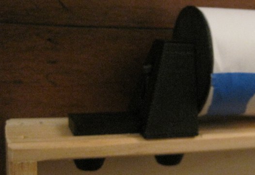
After their first stamp, I hacked together a 3D printed holder.  Despite measuring the erasers carefully, it was too long and really, too big for what it needed to be.  Here you can see version 01 taped to a piece of mahogany wood left over from my ukulele project.

This slideshow requires JavaScript.

There were several problems with this first attempt.  The holder was a little too long, so the eraser would shift back and forth.  It was also much bigger than necessary.  I designed it with those large fins on the side to make it easy to tape down, but it really wasn’t necessary and just made rotating the eraser holder a little more unwieldy.  While my kids were carving things using this holder, I went to work printing a few accessories.

3D printed screw top blade container, extra blade handle

3D printed screw top blade container, extra blade handle

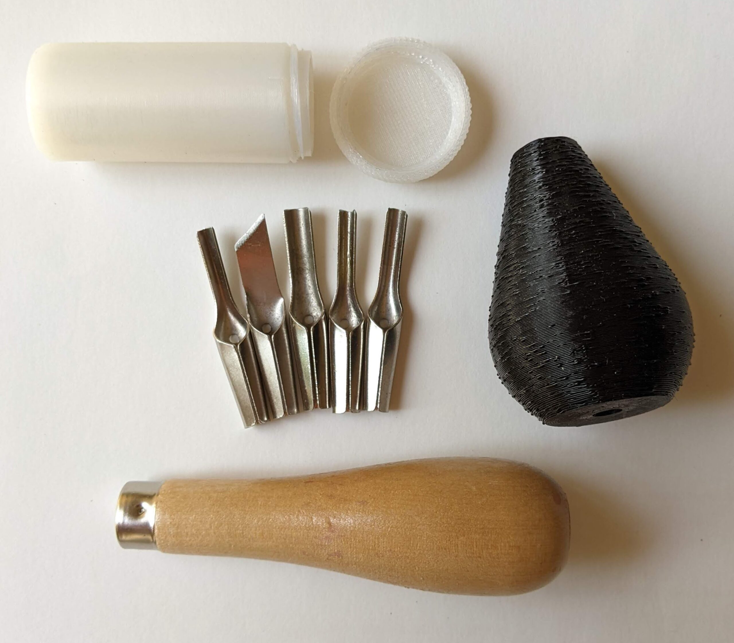
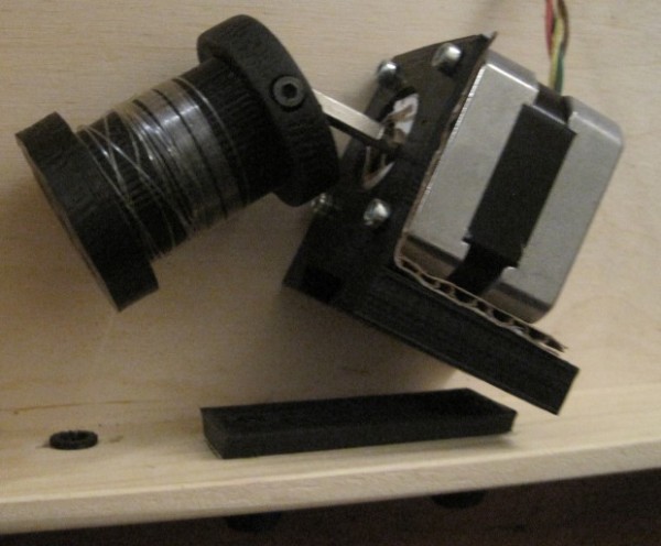
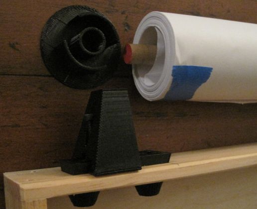
The blades came in a little plastic baggie, so I printed a bespoke screw top container for them so they can be stored securely.  I also printed another blade handle so that two people could carve stamps at the same time – one using the original wooden holder and the other using the printed holder.

The next version was more compact and had dimples on the edges which I hoped would make it easier to hold.  I also added some little ridges inside so the eraser wouldn’t fall through.  Here they are:

Eraser holders for carving, versions 1, 2, 3, 4, and 5

Eraser holders for carving, versions 1, 2, 3, 4, and 5

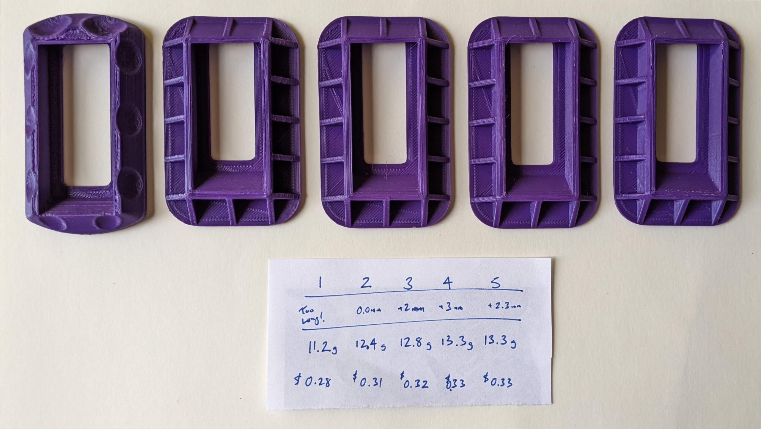
The dimples didn’t work.  They weren’t deep enough and my hand couldn’t really grip it very well to keep it from moving while I was carving.  The area for the eraser was a little too long.  Versions 2-5 involved tuning the length just right.  Each one takes about an hour to print and used about $0.30 of plastic.  The final result fit the erasers like a glove.  They nestle in the holder perfectly and are easy to poke out using the little hole.  Admittedly, they might only fit the specific cheap erasers I found.

Here’s my process:

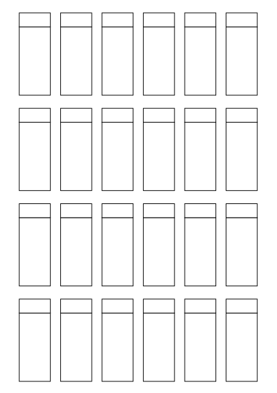
I created a page of eraser templates, which match the length and width of the large and small edges.  Of course, the long section matches the long side of the eraser – but the shorter section only matches the short side of the eraser if you tip it over.

Eraser templates

Eraser templates

I got to use several iterations of the eraser holder for this next section:

All the pieces, laid out nice and orderly

All the pieces, laid out nice and orderly

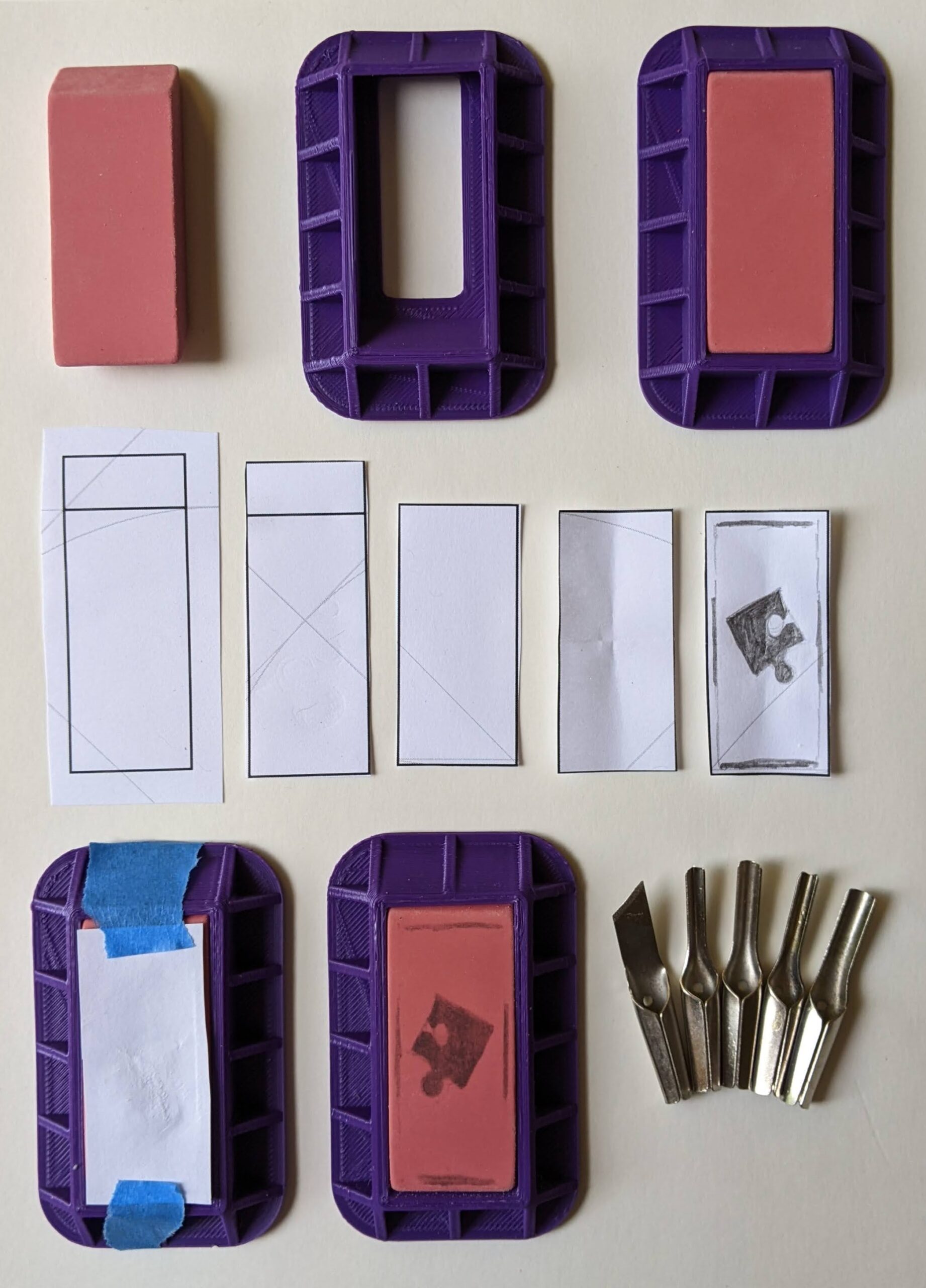
The process is pretty easy.  Put the eraser in the eraser holder – it should slip right in, drop in snugly, and lie flush with the top edge of the plastic holder.  After cutting out a paper strip, it’s trimmed to size, creased to locate the central point, and a pencil drawing (drawn as I’d like to see it printed).  This is taped upside down onto the eraser, rubbed along the back (a coin would work very well, but I just used one of the extra eraser holders), and the design is neatly transferred to the eraser.  The neat thing about this process is that I could design something in Inkscape, print it into the template, and color it in with the pencil for transferring to the eraser.

Lastly, let’s see the result!

Eraser stamp!

Eraser stamp!

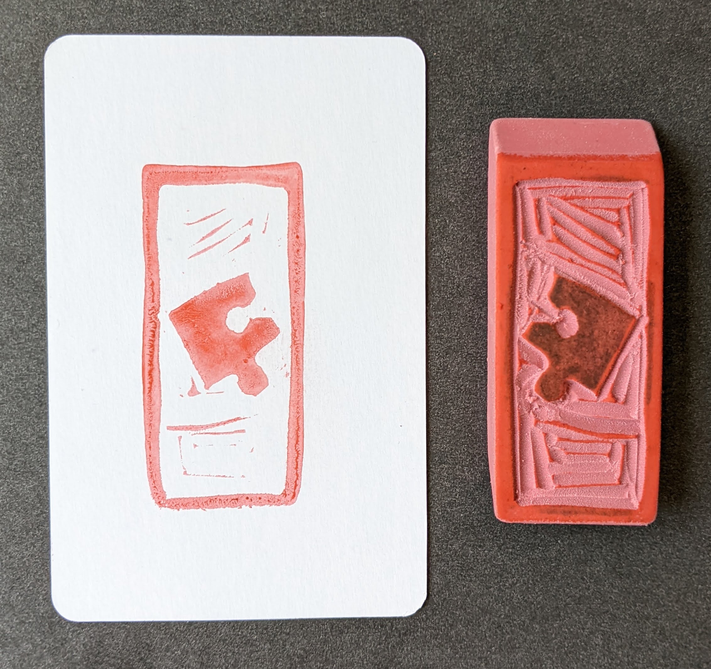
As you can see, the final stamped result matches the orientation of the little drawing.  I just wish I’d saved the little scrap of paper with the original drawing on it!  The eraser holder was a joy to use and the final result looks every bit as great as I was hoping.

If I keep making these, I’ll probably want to upgrade my setup to include Serena’s recommended stamp pad and sharpener (you’ll see them linked in Serena’s Amazon link above).  I’d like to design something to make easy to hold the eraser, center it, and make a clean even stamp, but don’t have a great idea for one yet.  I’ll keep pondering this and maybe whip something up this weekend.

Eraser Stamp Carving
  1. Carved Eraser Stamping
  2. Further Adventures in Eraser Carving
  3. DIY Carved Eraser QR Code Stamp
  1. I mean, I guess it’s version 1 – but I labeled all the purple ones starting with 1 so… []

Maker Faire 2018 – 3D Printing for Home Improvement

If you’re here checking out my site after my presentation, you can check out all the slides from my presentation above. If you’d like more information about the individual things in the slides, I posted an update for most of them over on Hackaday. If you’ve still got some questions, feel free to leave a comment below, hit me up on twitter, email me directly.

Practical 3D Printing for Everyone

This slideshow requires JavaScript.

3D printing can sometimes get a bad rap.  At first people are excited by the possibilities, then after printing a few trinkets the novelty can really start to wear off.  However, our 3D printers have become an absolutely critical part of our home repairs.

We have printed literally dozens and dozens of things in and around our home.  As of the time I’m editing this post, we’re up to 82 things so far!  The vast majority of these are completely bespoke custom creations, with a few things that are printed from Thingiverse or mashups with things from Thingiverse.

My proposed Maker Faire Bay Area 2018 Presentation submission is for a presentation that discusses:

  1. Practical things everyone can 3D print for their own home
    1. Repairs
    2. Improvements
    3. Other useful things
  2. 3D Printing with Family and Friends
    1. Specifying a purpose (“Honey, can you make me something that…”)
    2. Specifying dimensions and purpose (“I need something that will…”)
    3. Simple techniques for creating replacement parts (using good reference photos, GIMP, Inkscape, and OpenSCAD)
  3. 3D Design with Family and Friends
    1. Photographs
    2. Sketches
    3. TinkerCAD and Sketchup
Default Series Title

DrawBot – Printed Parts Tour

Drawing Robot - Preview

Drawing Robot – Preview

This is going to be another long in-depth post about my Arduino powered drawing robot.  If you’d like to know more about how to build one yourself, please help me out by filling out my DrawBot poll.  And, if after reading this post you find you want to know even more, be sure and check out the 68 preceding posts about the exact same topic, all listed in order at the end.

While you can build a drawing robot from 95% scrap, it does look better if you have the ability to design and print your own custom plastic parts.  While I’ve discussed my designs for the spools, stepper motor mounts, filament guides, bolt endcaps, and the pieces I use to hold the Polargraph case in place and I’ve taken you on a tour of the robot, I haven’t actually shown you how all the parts fit together.

While I’m quite happy with how everything has turned out, I haven’t had a chance to fire up the robot and actually try a drawing.  Once a few parts arrive from Sparkfun, I’ll be ready to give it a whirl.  Until then, please forgive me for not sharing these designs yet.  It’s less out of a desire for perfection1 and more out of desire not to strand some poor soul with some flawed printed parts.  Thus, I beg your indulgence a little longer.  Until then, I’d like to show you how all the bits I have so far work together.2

Filament guide and bolt covers

Filament guide and bolt covers

On the bottom left of the above picture you can see the filament guide – with filament helpfully sticking out of it.  Just to the right of that you can see two bolt covers/endcaps.

The filament guides ((One on the left, one on the right side)) serve several important purposes.  First, the monofilament line does not squeak when running through the smooth plastic filament guide as it does through a hole drilled in a piece of wood.  Second, it ensures that the two ends of the filament are always at a constant, precise distance from one another which is important for accurate and repeatable drawings.  Filament that is just spooling on and off can change position on the spool by a comparatively large amount.3 Third, the filament guides allow me to make sure the filament is flowing out of the box very closely to the back/bottom of the box – to help keep the pen holder/gondola against the wall.  Fourth, they just look nice.

The bolt endcaps serve some practical and aesthetic purposes.  Without these endcaps, the M3 bolts on the inside of the project box would protrude outside of the box beyond where they meet the 3mm nuts.  The protruding bolts can scratch or puncture and also make the overall project look a little raw.  One minor benefit to using these caps is that the force exerted by the bolt and nut as they are tightened against each other is spread out across the area underneath the endcap, leaving less marks on the project box.

For a project that could be easily disassembled, it would be interesting to create a variation on these plastic endcaps that essentially turned them into wingnuts.  As you will note from the upcoming pictures, many of these parts were specifically designed to make modular assembly/disassembly/modification a breeze.  Having had to pull these parts apart and reassemble them for these photos, I can assure you that taking everything to pieces and putting them back together is a cinch.

Exposed filament guide and stepper motor rail

Exposed filament guide and stepper motor rail

In the photo above you will see the filament guide once I’ve pulled it out of the hole in the project box.  I believe all I did was drill a 1/4″ hole, design the part to fit, press-fit the guide in place, and run the monofilament line through the guide.  I had to re-print these since the first pair was just a little too short.  Ideally the guides should just barely stick out from the project box, so that the monofilament never has to come in contact with the wood.

Once I get the ‘bot up and running, I plan to try using some endstops for automatic homing and printing.  I’ve seen several drawing robot designs that use metal contacts or simple switches to help the ‘bot automatically home before printing.  I think I prefer the style where metal contacts would go around the filament guides at either end, as they are less obtrusive on the exterior of the project box.

Just to the right of the tiny filament guide, you’ll see the plastic rail that I’m using to mount the stepper motors.  There are holes in that long plank of plastic with recesses for the M3 boltheads.  This rail or track or slide is held in place quite firmly by just those two bolts.  Once the rail is in place, the motor mount can be slid back and forth.  It’s a tight fit and would probably stay in place by itself, but why leave things to chance?  The motor mount includes a bolt and captive nut behind the motor, so that it can be tightened against the rail.

Stepper motor, fully installed

Stepper motor, fully installed

In the photo above you can see the stepper motor completely installed.  It’s not much to look at, but I rather like it.  You can just barely see the bolt just behind the motor that I use to keep the mount on the rail.  The setup is pretty solid and more than enough for the amount minor operational stresses they will endure.

Stepper motor, bolt loosened and off rail

Stepper motor, bolt loosened and off rail

In the above photo you can clearly see the top of the filament guide sticking out of the project box, the motor mount removed from the rail, the loosened bolt I use to keep the mount tight against the rail, and the corrugated cardboard I’m trying out for sound insulation.

Stepper motor off rail and spool off motor shaft

Stepper motor off rail and spool off motor shaft

In this view you can clearly see the bolt in the side of edge of the spool I use as a “set screw.”  The end of the spool has to be as thick as it is in order to accommodate the captive M3 nut.  While the other end of the spool does not have to be nearly as thick, I designed it to be symmetrical.4 You’ll also notice that the spool is not tapered on either end.  I designed the spool to be a two-piece bolt-together design.  This has the beneficial side effect of allowing me to trap the end of the monofilament line between the two pieces, rather than using a knot in the filament or some other such fix. ((OCD again))

End of spool

End of spool

Above you can see the end of the spool.  This is the part of the spool facing away from the motor.  Since I didn’t want the spool to be too unbalanced5 I didn’t want to use just one bolt on one side of the motor shaft.  I couldn’t use one bolt down the middle, since it would make the entire spool much longer than necessary.  Given that I was trying to make wide-diameter spools anyhow, it was little hardship to add a way to bolt the spool together on each side.  The end you see has two hexagonal holes to fit the M3 nuts and the other end has long holes going most of the way through, specifically designed to work with some of the M3x16 bolts I have lying around.

Paper roll mount

Paper roll mount

The paper roll mount system you see above were actually the first plastic parts I designed and installed into the project box.6 The entire assembly is pretty solid.  You’ll notice I used another set of bolt endcaps to keep the bolt threads from sticking into the project box.  While I didn’t anticipate them scratching or puncturing anything inside the box, I do really like the way they look.

Paper roll mount, disassembled

Paper roll mount, disassembled

Above you can see the paper roll mount system disassembled.7 The bolt is simply loosened, allowing the piece of plastic which has a circular hole for the wooden dowel to slide back, in turn allowing the paper roll to be removed easily.  You’ll note that the paper roll does not have any kind of cardboard core, as a roll of wrapping paper might.  This is why I had to create the thin endcap for the paper roll.  It serves to keep the paper roll centered on the dowel while preventing the paper from slipping from side to side.  The plastic rail for the paper roll mount is the same exact rail, only slightly shorter, that I used for the motor mounts.

PolargraphSD case installed

PolargraphSD case installed

When I designed the PolargraphSD case, I was mostly concerned about creating a case that didn’t use a lot of plastic and which could be easily mounted.  What I didn’t take into account was how I would end up mounting it to the inside of this particular project box.  In the end I had to design two plastic parts that would connect to the PolargraphSD case.  The beneficial side effect is that now the entire case is set off from the back/bottom of the wooden project box by the thickness of an M3 bolt head on each of the four corners.  It remains to be seen whether the vibration of the stepper motors would case the case to rattle.

Don’t forget to take a minute and fill out my DrawBot poll so I’ll know what to blog about next!

Default Series Title
  1. Perfection is the mind killer.  Perfection is the little-death that brings total obliteration. []
  2. Well, hopefully work together []
  3. I would estimate perhaps 10mm or more, depending upon your spools []
  4. Such is OCD []
  5. Like it’s designer []
  6. Sorry for the grainy photo []
  7. Hence, the caption []