I’ll start with some spoiler pictures, already posted on my Instagram account:
This slideshow requires JavaScript.
It was a very busy week at work, so I didn’t get a chance to work on the ukulele until this morning. I needed to shape the ends of the frets so they won’t be sharp and pokey while I’m playing, sand the 3D printed turnaround so it won’t abrade the ukulele strings, and general sanding of the wood body.
I don’t have a lot of pictures for it, but I sanded and wet sanded the 3D printed turn around. I used an old compostable tray left over from some prepared food. I just needed something to hold a little bit of water while I sanded the turnaround. There’s nothing fancy about this part. I sanded the turn around with 120 grit to get it mostly even, 150 grit to smooth it out a bit, then 400 and 1500 grit wet sanding paper to get it nice and smooth. I’m anxious to get this ukulele built, so I’ll probably install the turn around as-is. If the ukulele sounds good, I’ll remove the turn around, hit it with a light coat of spray paint (black or silver), and then reinstall it.
This slideshow requires JavaScript.
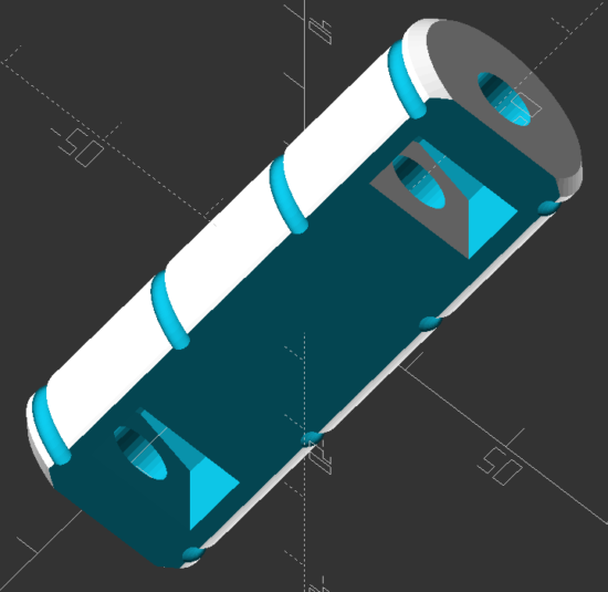
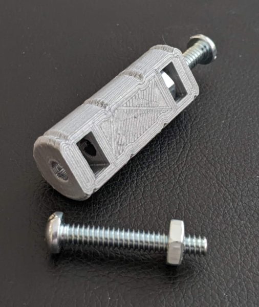
You’ll note the small 3D printed capped container. It’s a 45mm long, 15mm diameter double knurled cap version of this “Customizable Container with Knurled Lid” from Thingiverse.1 I’ve been posting things to Thingiverse since 2009 which almost seems like ancient history now. MakerBot launched the Thingiverse customizer in late 2012 or early 2013 and, unfortunately, 9 or 10 years down the road this functionality no longer works. This handy utility allowed makers to share not only their designs, but permit people unfamiliar with 3D design or programming to obtain custom STL’s of those designs. Although this tool no longer works, the underlying OpenSCAD code is fortunately still available. I used the script for the CCKL to create a small, narrow screw top container that was the perfect size for holding the frets, two machine screws, and two nuts.
Having a bespoke case for parts was a game changer for the way I work on projects. With a day job, kids, limited work space, and a longer term project, I frequently have to work on a project and then put it away for an hour or a week until I can have the time and space to come back to it. By putting a set of small parts into a custom container (that I could conceivably label) I can keep everything organized together.
I have spoken.
Filing and shaping the frets was time consuming, but not arduous. Based on the the time stamps in the photographs, I spent a little over two hours filing and shaping the frets and sanding / wet sanding the turn around. I first flattened or bent flat each fret, then used my finest hand file to taper the end of the frets, rounded them off, then removed burs.
This slideshow requires JavaScript.
While I was at it, I sanded the ukulele body a little more with the 1500 grit sandpaper. Taking time away from the project and then coming back allowed me the distance to find a few new slightly rough patches. I think there’s a few more to go, but nothing that will ever really matter.
The last week has been more planning and preparing than actual progress. However, this wasn’t so bad. Cutting off chunks of wood, filing gouges into a plank, sanding areas smooth all feel like progress, but all the little steps along the way are important too.
Raising the Grain / Sanding. My buddy Andrew suggested lightly wetting the wood, letting the grain swell slightly, and then sanding it back down. I watched a short video and read an article on the topic and gave it a shot. What do I have to lose besides $20 in wood and weeks of work?
I used a lightly damp paper towel and moistened the surface of the wood. After a few minutes, the water had visibly soaked in and the surface had become very rough again. I used the 400 and 1500 grit sandpaper that evening and then again the following day. Some parts are still a little rough and will probably need to be lightly sanded just a little.
I sanded the fretboard area so that it was mostly smooth, but not down to 1500 grit. I still wanted to leave some surface for the superglue to adhere the cotter pin / frets to.
Cut the Cotter Pins. This is a perfect thing to do during hot weather.
Reprinting the Template. This was another easy thing to knock out while staying inside.
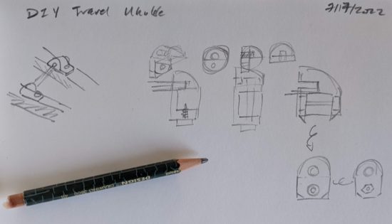
Planned the Bridge Bracket. I came up with several designs. Some are basically standard bracket sketches (the far left one looks similar to the hardware store 3/16″ ground wire straps Daniel used in his basic hand tool ukulele) and others are more novel. I have a few designs still knocking around upstairs, so I don’t know which I’ll go with yet. As far as I can tell, the bracket doesn’t really have to support any weight or meaningful force, it’s really just there to keep the bridge positioned correctly while the force of the strings on the turn around should keep it down and in place.
Sketches for bridge holder
I also made some actual progress this weekend. Some explanations and photos:
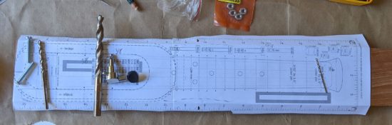
Printing the Template
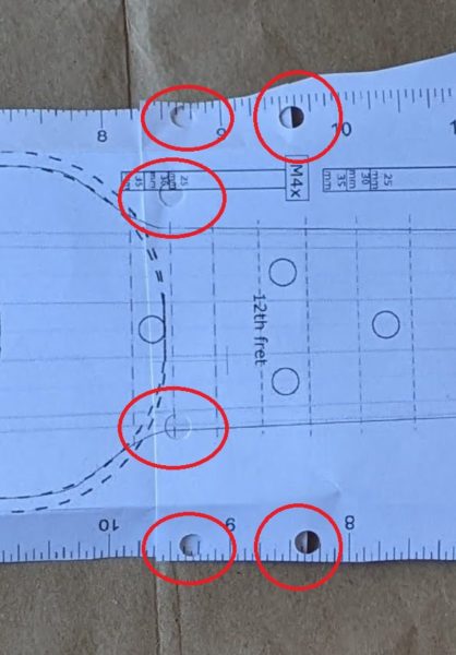
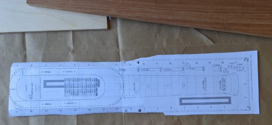
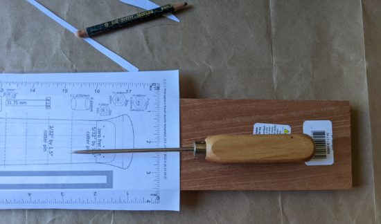
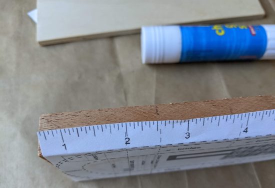
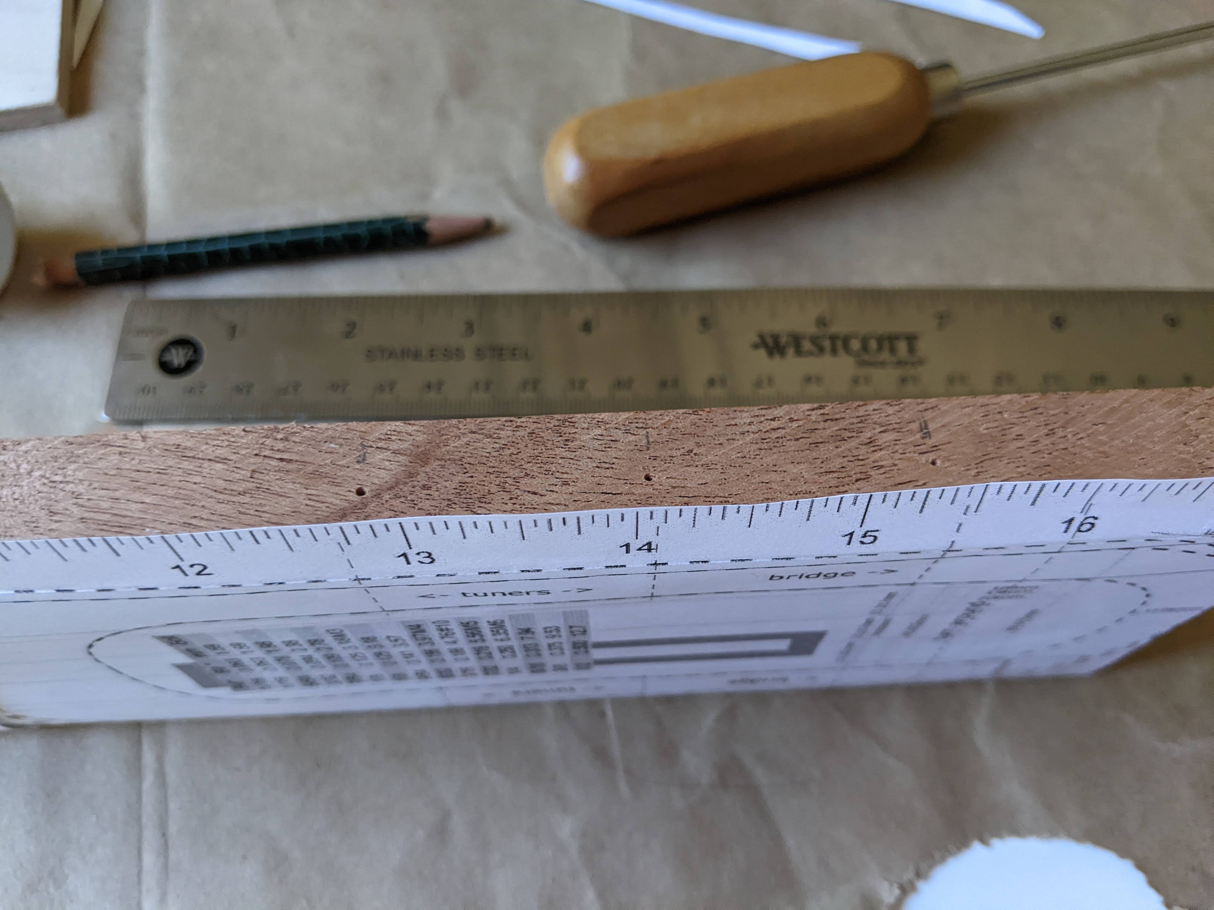
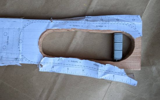
Since I don’t want anything out of scale or misaligned, I double and triple checked my printed pattern / template against a ruler. I’m happy to share the template, but please keep in mind at the time I’m writing this and sharing the document, I’ve never made a working ukulele. If you’re fine with that, here’s the template.
As you’ll recall, the template features a ruler on each side of the pattern, as well as a gray box 100mm long on either half.
When printing, be sure it is printing at 100% unless you discover your pattern is over/under sized, in which case, you can measure against the 100mm box to easily arrive at the percentage for scaling.
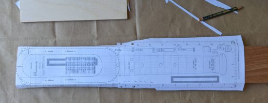
I also made sure to overlap the two sheets as much as the print dialog would allow, which was 2 inches. I figured this would give me more spots to orient and align the sheets of paper as well as more surface area for gluing.
This slideshow requires JavaScript.
Aligning and Gluing the Template
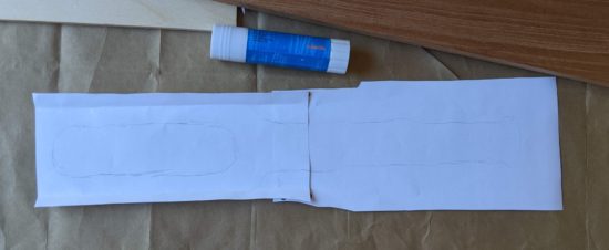
I removed excess paper from the sides of the two sheets of paper. Nothing fancy here, I just created a hard crease and tore the paper.
One of the two sheets needed to be trimmed slightly, so the sheets could be overlapped without any gaps. Once this was done, I also used a pencil to lightly draw on the top sheet approximately where the two sheets overlapped – so that I would know where to best punch holes.
Modern “shrinky dinks” come with these super handy small hole punchers. Since we did several of these projects with the kids, we’ve got a bunch of them left over. I keep one with my craft supplies and another with my office supplies. There were plenty of times when I’d be at a remote meeting (pre-pandemic) and want to add a sheet of paper to file or binder and these saved me from having to use the folder prongs or binder rings to puncture-rip the paper. 1
To create more “registration” holes towards the middle of the design, I folded the pattern, then punched again.
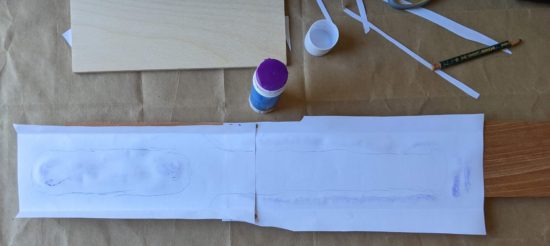
I wanted to glue the pattern together, but the print is on the front. To keep the sheets from shifting, I cut up the sticky part of a post-it note, and used these to lightly affix the sheets together. Once aligned and lightly stuck, I flipped the paper over, used a gluestick, and pressed it flat.
The problem with using paper is that it’s not translucent, so you can’t really tell whether you’re aligning things properly. To get around this problem, I used a toothpick to punch holes where the strings go into the neck past the zero fret, using some closed cell foam underneath.
Using some needle nose pliers, I cut and bent two small “L” shaped pieces of a small paperclip that could be dropped through the holes in the paper into the string holes in the plank.
I trimmed some of the paper and used some blue masking tape to hold the pattern steady. I didn’t want those little paperclips having to be responsible for the entire sheet of paper not shifting.
This slideshow requires JavaScript.
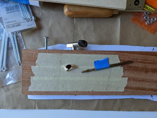
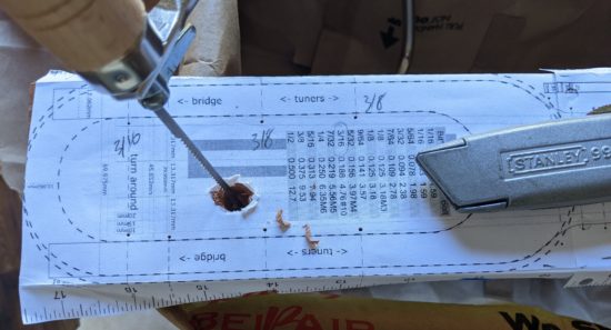
Marking locations for zero fret, frets, fret markers, and bridge
There were several steps along the way I slightly dreaded. The first time drilling into the plank of wood, the first time I took the coping saw to the plank, cutting the round rod to size, reprinting the pattern and getting it right again, and possibly above all else putting down the lines for the fret markers. Two people who followed Daniel’s designs reported their ukuleles didn’t sound quite right and attributed this to the fret placement. It would be a real shame to put this amount of time into a project only to have it sound terrible. I’ve made every effort I can to get these fret lines as precise as I can.
This slideshow requires JavaScript.
Cutting and labeling zero fret, frets
The first cotter pin I clipped ended up with both pieces flying around the room. In an effort not to repeat the same mistake, I cut the rest of the cotter pins inside a fleece cap. Although both pieces continued to be ejected from either side of the wirecutter jaws, they didn’t go anywhere and did no damage to the cap.
The frets get progressively wider as they travel down the neck to the bridge. With some really hot weather and less-than-ideal air quality due fires, I was pretty sure I wouldn’t be filing down the cotter pins today, so I wanted to make sure to label them as I went. A quick fine tip sharpie mark to the topside of the cotter pin let me know where to clip it and some Roman numerals to the underside to keep them straight made sure I could easily pick up where I left off later. As the picture captions below suggest, I used Roman rather than Arabic numerals because it’s a lot easier to write little lines and crosses on a small bit of metal than it is to write a 3 or 8.
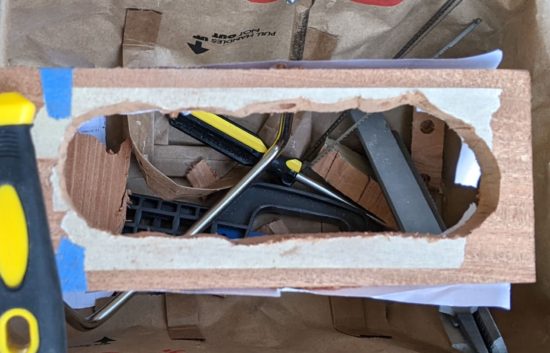
With the cotter pins clipped, I 3d printed a 15mm diameter 45mm tall screw top container to hold them. It took $0.14 of plastic and 30 minutes to print. Yes, it is ridiculously custom and niche, but once this project is done I will undoubtedly reuse it for some other purpose.
I suspect some of the cotter pins might have gotten slightly bent in the cutting process, so I’ll need to remember to bend them flat before I glue them down.
This slideshow requires JavaScript.
What’s left?
Using a metal file and then sandpaper to round, taper, shape, and soften the sharp edges on the cotter pins.
Making sure the cotter pins have not been bent out of shape – and bending them back as necessary.
Gluing down the cotter pins.
Sanding the fretboard smooth.
Wood finish and wet sand, dry, wood finish again.
Wax.
Design / print / install bracket holding bridge in place.
Install tuners (possibly with some 3D printed washers).
Sand, possibly paint, and install the turn around.
This barely qualifies as an update. Or even any kind of a meaningful incremental improvement to include for this blog / project notebook. However, I’m so pleased with the look and feel of the progress, I couldn’t help take a few pictures.
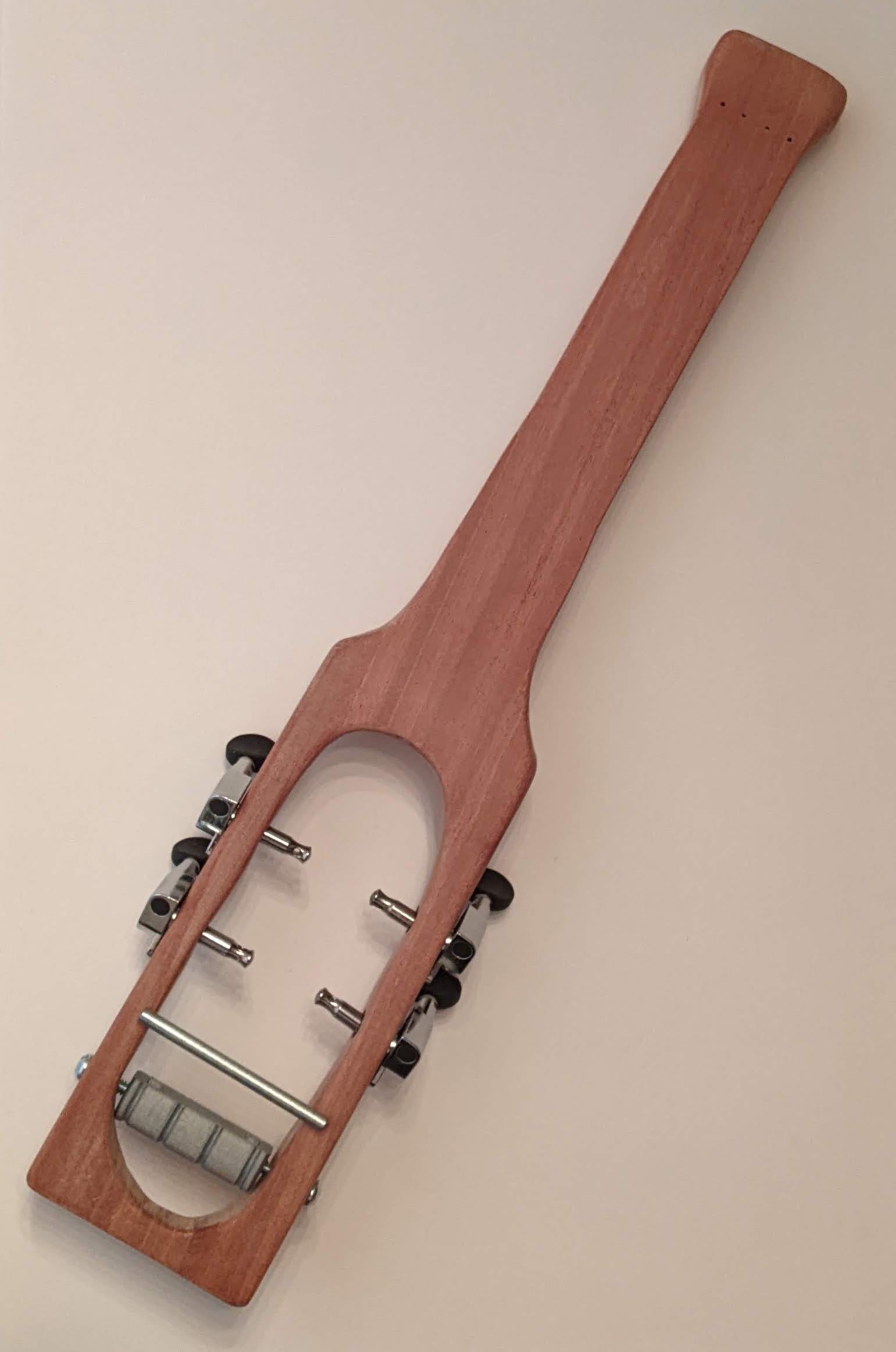
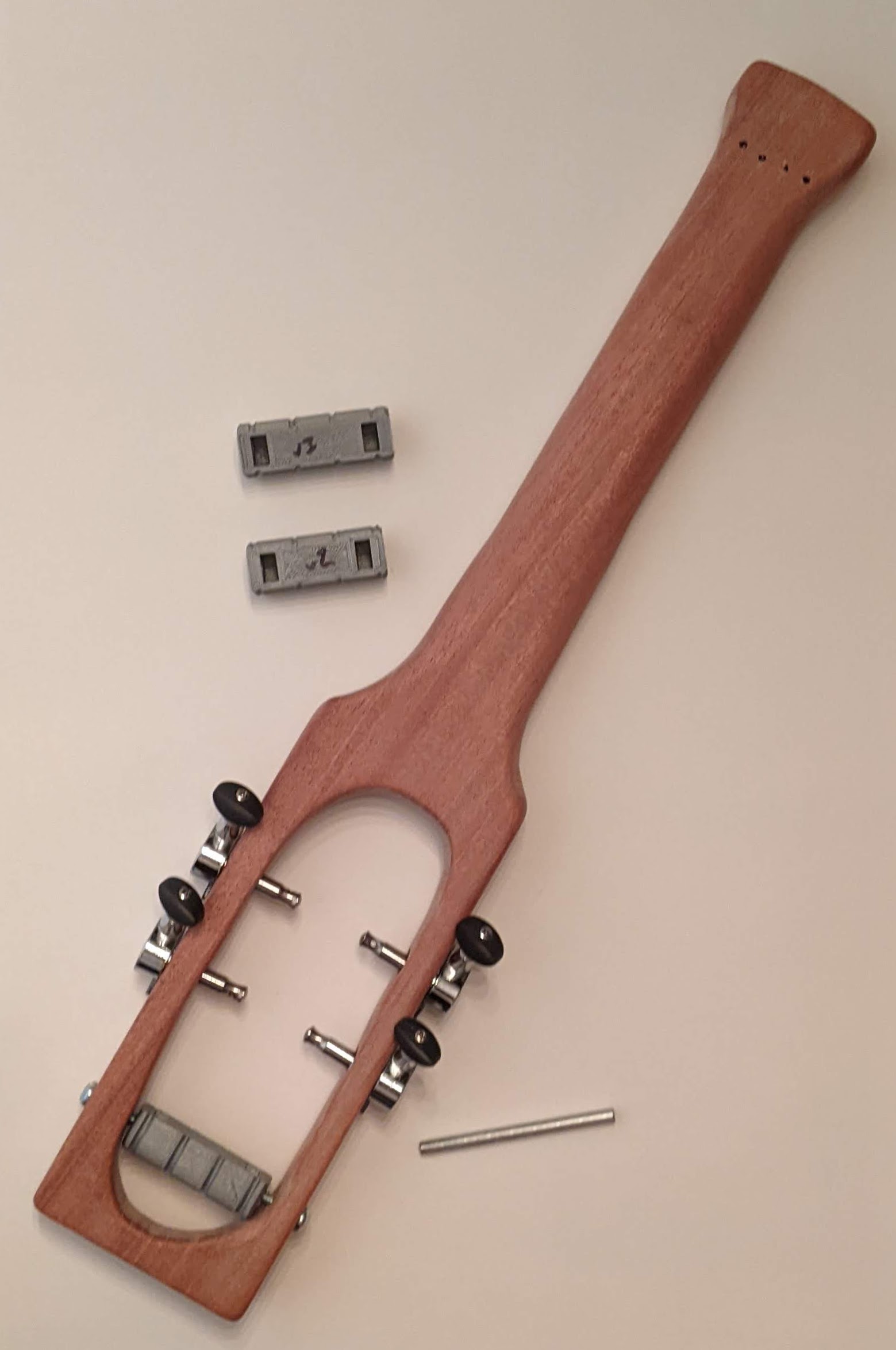
Test fit tuners and turn around
From the underside, with several prior iterations. The very first design / print of of the turn around didn’t have large enough holes for the hex nuts. The second version would still work, but it was about 5mm shorter than the final version and not as cosmetically pleasing. The third version was just barely too wide. I suppose I could have filed or sanded it to fit… but why? I have a 3D printer and it would only take 30 minutes for another version and a perfect fit.
A 3D printed model involves very light layer ridges. I am a little concerned these ridges could, over time, abrade the ukulele strings. Before test fitting them, I used a very thin fine file to smooth out the grooves in the turn around.
The underside, showing two prior (shorter) iterations, bridge uninstalled
In the photo you can’t really see the gap between the tuners and the wood, but you can see the tuner pegs are very slightly angled. This is because the holes I drilled were, unintentionally, very slightly angled. While this isn’t likely to adversely affect the tuners, string tension, or operation of the ukulele, the tuning pegs won’t sit flush against the ukulele body. My options are either to put the drill to it again (for the third time), live with the cosmetic look, or add a washer of some kind. I think the best option is to design a thin, lopsided washer, that I could tighten the tuning pegs against.
I am very happy with the way it’s shaping up! It’s starting to actually look like a ukulele.
There wasn’t a lot of magic to today’s work. My time was probably 29% filing, 70% sanding with successively finer sandpaper, and 1% brushing dust.
A few notes:
Filing. I bought a set of files years ago at Ace Hardware. They had a bargain bin and a set of files – with one missing. I asked for a discount, got it, and these have served me well ever since. I found it helped to brush these off as I worked.
Sanding. I’ve had a modest selection of sandpaper ever since I started work on my first 3D printer kit back in 2009. On this project I used 100, 120, 150, 400, and 1500 grit sandpaper. I believe the last two are “wet” sanding paper, but I kept the process dry – occasionally hitting the board and the paper with my brush.
Gouges. I really went after these and was able to file them out for the most part. However, there are a few spots left. The gouge marks are small and I really felt like I hit diminishing returns on my effort.
Fretboard. After a little agonizing, I decided to sand the fretboard lightly. Now it’s smoother, but all the pencil lines are completely gone. Since yesterday I’ve come up with some ideas on how to put these back on.1
The result is a very smooth vaguely ukulele neck shaped piece of wood. It is very nice to hold.
I found that no matter how finely I sanded the piece, once I rubbed it with a piece of cloth2 I could feel the smallest little burs afterwards. I think some of this may just need wait until after the first layer of finish.
This slideshow requires JavaScript.
I believe most of the “outside work” is done now. I need to:
Cut the cotter pins into frets. Sand the ends down so they’re not sharp.
Measure and redraw zero fret, frets, and bridge lines.
Glue down the zero fret, frets, and bridge lines. I would estimate roughly 99% of the chords I play are A, F, C, G, D, Dm, E7, Em, and a few similar such chords. Really, nothing past the first fret marker. I’ll probably do this in the evening when the weather is slightly cooler, so I can have better ventilation.
Once the frets are glued in place, I would probably sand between them again. I didn’t want to make the fretboard too smooth, otherwise I might have removed some of the texture needed to form a good bond between the metal and the wood.
Measure, adjust design, re-print, and install the turn around.
I haven’t given any thought to fret markers or side fret markers. I should probably do so now.
Once I’ve decided about the fret markers, I would then move on to the finish. From viewing Daniel’s videos and other woodworking videos recently, I would wear some gloves, brush and dust the wood, apply the finish with a cloth, and then sand while it was still wet – so the sawdust could go into any open pores. I’d probably sand again with the 1500 grit sandpaper, finish / sand again, and then move on to the wax.
I have some ideas to prevent the string ends from being too pokey. Perhaps 3D printed string beads or perhaps tying the string around a 3D printed item and fed back into the holes for the strings.
I pretty much only make progress on my ukulele on the weekends – and even then only for a short period in morning since it gets so hot so quickly.1 Unfortunately, last Sunday I didn’t get to it – and as a result spent the workweek daydreaming about what I’d do on Saturday morning.
Here’s what I planned to do:
Filing and sanding. Of course.
Increase the diameters for the holes for the tuners. After a few test fittings, I found the holes for the tuners were pretty snug. I wanted to widen these just a little to make them easier to insert, hoping they would end up flush against the ukulele body.
I’m pleased with my progress so far – it’s not onerous, but it is slow. As with so many things, it’s the journey, not the destination.
Cutting the round rod with the hacksaw went reasonably smoothly. Rather than going for a particular length, I aimed for a length that would go from either side of the body, with about a quarter inch to spare. I marked the spot with a sharpie, cut until I got mostly through, and bent the soft metal until it popped off. I used my full hacksaw instead of my smaller hacksaw and it went quickly. Then I filed down both ends so it wouldn’t be sharp. I don’t like any of the hardware store options and will be designing a 3D printed piece to hold it in place.
Counter sinking the string holes and widening the tuner holes went easy enough. I really should have done these at the beginning, but it’s all a learning experience. I suppose I could have drilled out the turn around hole some, but the machines screws went in and came out fine already.
The filing and sanding isn’t difficult, it’s just slow.
In the photos below you’ll notice I used a soft pencil to draw in and around some of the saw and file gouge marks. I used my medium and fine files, then started with 100 grit, then 120 grit. I still some light gouge marks on the outside to remove, some unevenness to the neck to straighten out, and much of the interior of the body to file, shape and sand. I also made sure to follow Adam Savage’s advice and regularly swap out the sandpaper. There’s no point in rubbing this thing with sandless paper.2
The interior really jumps out as the least attractive part right now.
I gave the outside of the entire board a good sanding to smooth it out – except for the fretboard area. I’m loathe to sand this part and remove the markings for the frets. The fret and bridge positions are critical to getting the sound right and I don’t want to screw this up.
I took turns filing and sanding to get the shape I wanted – then started using the pencil to highlight the areas needing attention, sanding, and then an old toothbrush to remove dust. I have a small supply of the kid’s old toothbrushes for these kinds of tasks. After they’re done with them, I’ll wash them and use my heavy duty clippers to cut them off about 1-2 inches below the bristles. I keep one with my drill bit set, so I can remove dust and debris from the bits before they go back in.
Anyhow, by the time I was done with the neck, I was genuinely surprised how nice it felt to hold. It kinda feels like a ukulele.
This slideshow requires JavaScript.
What’s next? I’m glad you asked!
Still more filing, pencil marks, sanding, brushing.
Using my small thin round files on the string holes so they’re not so sharp.
With particular attention paid to the inside of the body (where it’s pretty rough) and the head (which needs a lot of shaping).
I’m genuinely undecided about the bottom of the ukulele – whether I want to keep it flat or round it off. It’s a lot of wood to remove by file, so I’d probably need to cut into it again if I decided I didn’t like it.
Gluing the zero fret and frets.
Measuring and printing a new turn around. I filed away enough of the interior that although the original turn around would work, it would look a lot better with a new one.
Ordering the finish and wax. I’ll probably go with Daniel’s suggestion for Birchwood Casey gun stock finish and gun stock wax. They’re inexpensive, come in small bottles, and are easy to order off Amazon. I suspect a single bottle of each would be good enough for many more ukuleles than I’m likely to build.
I like the idea of black hardware. I might still pick up some black oxide finish machine screws. Or, I might just await until I finish this ukulele and see how it sounds.
Once the finish and wax come, it’s back to more sanding, finish, sand, finish, then wax. :)
Things I would do differently the next time around:
I would definitely NOT use my awl to put such large holes into the wood. I would have not filed or sanded off as much in many areas if I hadn’t put some of the pock marks into the wood. I don’t know a great way to transfer the design to the wood – but I’m certain this is a problem that’s been solved in the last several thousand years by better minds.
Throughout this entire process I keep thinking “Dang, this would be a lot easier / faster / better looking with a bench vise.” It would have been very helpful to have it for holding the plank while I cut with the coping saw, allowing me to keep the blade perpendicular to the wood, rather than at an angle as I held the plank with one hand and the saw pivoted slightly. It would have been helpful with the drilling, filing, cutting the round rod, and sanding.
If I had a workshop or garage space I would immediately put in a work bench, bench vice, a used drill press, and a nearby station for my shop vac. I’d be tempted to add a used band saw too. I’ll add these to the wishlist for my next home.
It was going to be hot in California today, so after my morning coffee I went out to the backyard to work on my ukulele. I already had the center sound hole cut away and part of the neck – now I needed to cut away the excess from along the neck and shape it.
Here’s some photos with some short descriptions. Some notes on my process after.
This slideshow requires JavaScript.
I know the sound hole is wonky. I’d aggressively attacked it with my most course file, but it’s not a great way to remove excess wood. I may just up for a slightly lopsided cavity because it will never matter to the sound or the only person who’s ever likely to play it.
The coping saw worked really well today. The blade that came with the coping saw would probably be described as “fine” and it broke pretty quickly. After I bought new blades, I replaced it with the most course blade of the assortment which also broke pretty quickly. I strongly suspect it had more to do with my (lack of) technique than any unreasonable defect in the blades.
This slideshow requires JavaScript.
The techniques that probably contributed to broken blades:
As I sawed downwards, I would also put a lot of downwards force on the blade. I found that I was putting force on my thumb along the handle, which created a lot of force on a single point on the blade. I believe if I had focused on putting force along the teeth, in line with the blade, I don’t think I would have broken the blades as easily.
Sometimes, as I was trying to maneuver the blade, I found myself trying to cut an angle by pushing the blade sideways – since it wasn’t possible to rotate the blade since the frame would have been blocked by the neck or the body in some way. I believe if I’d managed to rotate the blade a little more, it would have allowed me to avoid breaking the blades.
Things I should have done better:
I should have gone slower or been more careful with the course files. I added a few more gouges than I should have in a couple of areas. Hopefully by the time I’m done they’ll either be fixed / filed or sanded out or have become part of the charm and character of the ukulele.
When I removed some of the blue tape, it stripped some of the wood off the face of the fretboard. I’m not sure what I could have done to prevent this.
Using my awl to mark the board worked well in some spots (way to the sides of the fretboard) and terribly in other areas (around the curve of the body and above where the strings go into the neck). These are difficult to file or sand away. Next time I would make lighter indentations as they get closer to the areas to be cut away or just find a way to draw them in with pencil.
Things I did that worked well:
Making the lateral cuts along the neck (with the hacksaw) really helped. Not only did it seem to make removing each successive section of wood easier by allowing me to get them out of the way, it also became easier to maneuver the blade without those sections in the way. It also helped me have little goal posts to point the blade towards as I cut.
Rather than using the two “techniques” above, rotating the saw blade when I could or when I couldn’t, some combination of reversing the blade and/or putting the saw inside the sound hole really helped.
Still saving the cutoffs so that I can test superglue, wood oil, and wood wax later on. Excepting the sawdust, I’ve probably saved 95% of the pieces coming off the board.
Improvements I may yet make
I doubt the project requires a solid piece of metal running all the way through the turn around, but I could always swap out one of the two 1.25″ #10-24 machine screws for a 1.5″ screw, to provide more support. I’m not going to bother doing this unless it looks like the turn around seems to be bowing to the pressure of the four strings.
I didn’t print the turn around with the highest possible resolution settings. Even if I had, due to the nature of printing curved top surfaces, it would always look a little rough. Once the entire ukulele is assembled, it wouldn’t be that big a deal to loosen the strings, pull out the turn around, and replace it with a nicer one. This could be achieved by simply printing a new turn around with a finer resolution, sanding it a little, and then hitting it with a little spray paint similar to this one at NorwegianCreations. I would probably print the design with deeper grooves for the strings too.
Things I might try on a second go-around
The 3/4″ thick plank of wood is a bit thick for the neck. I suspect I’ll need to file or sand a fair bit away before it feels comfortable and natural to hold. It’s possible using a thinner piece of wood for the entire project might work out well, possibly down to 1/2″ thick. The obvious problem with going any thinner than 3/4″ is there won’t be enough material to drill into to install the tuners. While this could be solved with some 3D printing wizardry, I want a mostly natural wood ukulele, rather than a plastic / wood hybrid.
I think a router might be a good way to cut carve this project out. There are some possible problems, but nothing insurmountable. I don’t have a work bench or vise to hold the project steady while I routed the wood. I could possibly work around this by setting the project down on a small piece of plywood, then drilling some scrap wood around it on four sides to keep it from moving. In thinking back to one of Daniel’s instagram posts, I remembered he used a small router with a roundover bit to make the neck more comfortable to hold. From the short video, it looks like he’s using the “Drill Master 1/2 HP 1/4″ Trim Router” from Harbor Freight. It’s $30 right now, but the reviews suggest it’s been on sale recently for as low as $20. I don’t know if it’s powerful enough to rout all the way through a piece of 3/4″ hardwood.
I have some ideas on how I could create a more cylindrical turn around. It would be to create the turn around in two halves that each have a section the machine screws go through, so that once it’s put together and the machine screws inserted, they’ll stay together. However, I really don’t think the very slight cosmetic differential is worth the additional effort and engineering time.
There doesn’t seem to be much of a reason, besides spacing, for the turn around to be so far down the body of the ukulele from the bridge. I would think the turn around could be almost directly under the bridge. Either way, even if the bridge didn’t have brackets holding it down, it would still be held down in place by the strings pressing it into the wood. In this case, I would think it possible to create an integrated bridge / turn around. The real difficulty would be that there would be no good way (absent even more engineering) to make the bridge location adjustable to ensure proper spacing.
The photos above were over the course of about two hours. I suspect I’ve got another two hours of additional filing and sanding to go – and that’s if I don’t try to file the sound hole to a more symmetrical shape.1
My next steps, roughly:
More filing and sanding
Filing and sanding down the gouges
Softening the corners and edges
Adding more of a curve under the neck
Moving from the coarsest file down to my finest file then from my coarsest sandpaper to the finest
Wiping all the dust off
Drilling a slightly larger hole under the neck, so the string knots are buried inside the neck, rather than poking out
Erasing bad fretlines and drawing in better ones as necessary
Wood oil and wax to finish
Looking through Daniel Hulbert’s various ukulele tutorials, I found a reference to “Tru-Oil finish with a gunstock wax polishing.” These appear to be products used for gun stocks, but according to their reviews and several other blog posts out there, other wood projects including guitars!
The good thing about these products, the “Tru-Oil gun stock finish” and “Gun stock wax,” is that they’re both reasonably inexpensive and small (only 3oz each). I don’t plan on making a ton of ukuleles, so I don’t want to end up with piles of power tools and buckets of liquids at the end of this project.
I still need to order the finish and wax. I think I’ll also save some cardboard boxes to build something I can use and leave outside. I’m thinking of a box with some holes for wooden dowels in the sides, so I can hang the ukulele while in between coats of oil, similar to the way Soph made hers.
Tuners, bridge, turn around, and strings
As I filed down the inside of the sound hole, it’s been widened somewhat, so I’ll need to measure the spacing and re-print the plastic turn around. No big deal.
Hacksaw off a ~2.5″ wide piece off the 3/16″ zinc round rod.
I’ve noticed the strings on my actual ukulele have slight grooves on their underside, on my most played chords.3 The strings are otherwise still good – so I suspect I could pull them off my ukulele and put them into use on my DIY ukulele. That’s the plan, anyhow.
The tuners are easy enough to install. I’ve test fit them a few times – and looking forward to adding them at last.
Today was mostly about just cutting and shaping the piece of wood. Gallery with descriptions below.
This slideshow requires JavaScript.
What I didn’t really show in these pictures was me shaving the wood with several different hand files and rasps. One side of the “sound hole” was a lot wider than the other – too wide to put the tuner through. I made heavy use of my most course rasp to remove a lot of wood from that side, then the more fine rasps to smooth everything out. I used the smallest of my files to widen the holes for the tuning machines and turn around a little. These will come in very handy when it’s time to shape the underside of the neck.
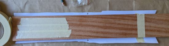
I taped the board to protect the pattern, then drew the rough outline on the masking tape. I did this on the reverse too.
Cutting out the sides of the neck was very slow going with the blade rotated 90 degrees. As I was cutting, I did think again about how much easier it would be with band saw. However, I really did want to make this ukulele with hand tools (plus my electric drill), if at all possible. Plus, I don’t want to buy or even store equipment I’m not going to use all that often.
For anyone following along at home, I think a router would probably be the single best power tool to help on this project. A quick search revealed routers started at about $60 and scroll saws started at about $110. If I were to try and make another ukulele, it might be worthwhile to pick up a router. It probably would have reduced a multi-day coping saw / hacksaw process into about 20 minutes.
Of course, the best overall tool might well be a CNC router. ;) That would have made quick work of the entire process… 1
What would one of my blog posts look like, if it didn’t involve wild digressions? The saying, “Everyone has a plan until they get punched in the mouth” is attributed to Mike Tyson, speaking of the impending fight with Evander Holyfield.1
I’ll post some pictures, but suffice it to say very little has gone according to plan. :)
Travel Uke Design
I got started by putting together a pattern based on Dan Hulbert’s designs. A few notes about how I put it together:
Designs
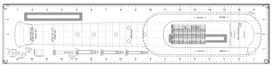
I started with Dan’s designs, specifically the “backpacker travel ukulele,” added a rounded base similar to his concert sized “travel ukulele,” and then added a number of annotations. I wanted to have a way to visualize the size of the bolts, hardware, etc. I also added a grid showing the various drill bits, keyed to the various hardware.
Process
I created the above described design in Inkscape, using different layers for different aspects of the design.
Printed the design on two sheets of paper, lined them up, and glued them together. I used a hole punch in the top sheet, to help line them up easily. I made sure to put the hole punches through parts with lots of detail, but nothing critical to the pattern.
There are rulers on every side of the diagram, and a 100mm wide gray box, because the first several times I printed it out the scaling was all wrong.
I’m not sure why the scaling was wrong – it could have been somewhere in the conversion process from SVG to PDF to a two-page PDF. In the end, I just measured the box, found it was too small, scaled up the next print, and it was close enough to 100mm that it was fine with me.
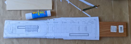
I picked up the wood (a 3/4″ x 3″ x 24″ mahogany plank from Rockler Woodworking), hardware from Home Depot (I’m pretty sure they lost money shipping me a 4′ long steel bar), and 3D printed the turn around.
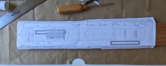
I used a pencil to trace the reverse side of the design. This way, I would be sure not to put glue in any of the areas that would touch the final design. I then applied glue and glued the pattern to the wood using a glue stick.
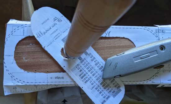
I used a utility blade to cut out the center “sound hole” paper outline, making it easy to cut out the center.
Used an awl to poke holes through the pattern where the strings go above the zero fret, on either side of the frets (so I could draw a line on the wood between these indentations for the fret locations), and other locations where I needed to drill holes.
Taped the bottom of the wood, so that holes drilled and saw cuts wouldn’t cause the wood to splinter. I really should have taped the top too, but I’m learning!
Drilled a hole in the “sound hole” to put saw blade through.
I don’t have a scroll saw, router, drill press, or CNC – any of which would have made the rest of the process a snap. Instead, I bought a coping saw and cut part of the sound hole out.
Snapped the blade. Bought some new blades. Cut the rest of the sound hole out, snapping another blade in the process.
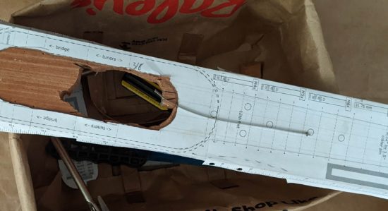
I installed the turn around – which looks like it is going to work well.
Hole punches through the top pattern allow the sheets to be aligned properly
Paper lined up on the board
Drawing on the reverse of the pattern
Glue in just the areas not touching the design
Glue!
Poking holes through the pattern
Taping the bottom of the plank
Hole through the center, for the coping saw blade
Drill bits and hardware
Coping saw blade through the hole
Center pattern cut out with utility knife
Awl ready!
Marking spots for the awl holes
Marking the wood for the holes to be drilled
Partially cut, broken coping saw blade
Cut out, tape still on
Render of 3D printable turn around
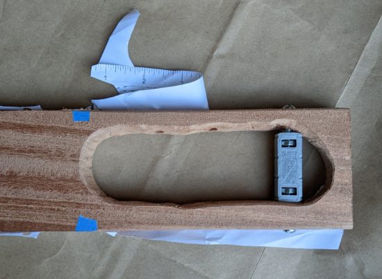
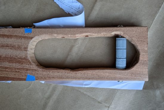
Printed turnaround with captive nuts and hardware
Masking tape removed, filed down somewhat, turnaround installed
Turnaround installed and rotated so the captive nuts are out of view
Top view
The result is … wildly uneven.
Improvements
As with any project, I find that as I am going through the first iteration2 I discover a few ways to improve the existing plans. Here are some ideas I had along the way:
Creating the template so that I can fold the left and right sides down and they will indicate the precise location for the tuners and turn around holes.
Including dotted lines from the widest part of the design all the way up – so I can be sure the pattern is straight all the way up the plank of wood.
Create a cross hair pattern for the places where I need to drill, to make my awl punches through the design more precise.
Add measurements to the gray scale boxes. (Quick tip – the boxes are exactly 100mm long with 0.0mm thick outlines. This prevents them from being draw very slightly too wide).
Tape the top and bottom of the board, as well as sides, before drilling and cutting, to prevent the wood from splitting or splintering.
About two years ago I received a ukulele for Father’s Day and started playing it. It’s an instrument I’ve always been interested in, but nothing I’d ever put any effort into. Thanks go a world-wide pandemic1 I had a little extra time on my hands and figured I’d really give this a shot. Who knows, maybe I’d come out the other side of this pandemic with a new skill? Two years on and I can play several songs, carry a tune, and find it relaxing and enjoyable to play.
Focus + Practice + Time = New Skills
Part of my approach was to see if I could set aside some time every day to devote to learning. I thought back to a TEDx talk by Josh Kaufman entitled, “The first 20 hours — how to learn anything.” Josh outlines his process for learning the ukulele in 20 hours.
The essence of this talk is stuff we’ve heard a hundred times before. Small incremental improvements become big gains over time. Josh cites Malcom Gladwell’s theory that “ten thousand hours is the magic number of greatness” as argued in his book “Outliers” but points out the 10,000 hours is to achieve world-class, expert-level greatness. Josh argues all you really need is twenty hours of focused deliberate practice to be pretty good at something. 2 This is amusingly similar to the Pareto Principle that “for many outcomes, roughly 80% of consequences come from 20% of causes.” This 20% of world-class effort, spread out over time, leads to surprising incremental improvements. 34 But, effort and time isn’t enough – it’s the particular focus. Fenyman’s learning technique is uniquely designed to help identify these features. A gross oversimplification of this method is: write down the steps as if you were explaining it to someone5 , identify gaps6 , organize / simplify and go back to the first step.
My Learning Process
What does all this rambling mean? This website tends to be my sketchbook / journal for projects – especially projects where I am starting from scratch. When learning a new topic or skill, my approach tends to be:
Watched this ukulele tutorial series by “Andy Guitar,” probably dozens of times, while trying to follow along on my ukulele
Found songs using the easiest beginner chords (Am, F, G, C)
Retyped song lyrics, with the chords interspersed, in a way that made sense to me7
Practiced those chords and songs
Found more songs using additional chords (Dm, E7, Em, D, etc) and repeated steps 2-4
Building a DIY Travel Ukulele
But, this post isn’t about playing the ukulele. It’s about building a ukulele. Documenting all of this helps me organize my thoughts, get them out of my brain (since I know I can always return here to find them), and free up my attention to move onto new problems. (Perhaps most importantly, it lets me close dozens of browser tabs.) I’m not sure how I first stumbled across Daniel Hulbert’s YouTube videos and website, but ever since seeing some of his designs, I haven’t been able to shake the idea that I want to build my very own quiet little travel soprano ukulele.
If you’re following along so far, I’d warn you that as I’m writing this I just have a piece of wood with some holes in it and bits of hardware lying around. I would not consider what I have to be a tutorial at all. 8
Existing Tutorials, Resources, Examples
After looking at Daniel’s various designs, I also looked at several travel ukuleles (most inspired by Daniel’s work):
I designed a 3D printable model, but have yet to print it. As I worked on the design, I deconstructed other designs I’d seen, looked at the important parts, including some from Daniel’s templates, and tried to keep the critical components and think about the various design choices he made in building his own instruments. However, I don’t think I ever will try to print this. From a learning perspective, it was an excellent exercise – but I think I’d much rather have a wooden travel uke.
Anatomy Lesson
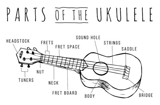
First, a bit of anatomy, swiped borrowed from the Kala website. (I wanted to leave a message letting them know I was borrowing the image, but the post doesn’t allow comments.)
Parts Of The Ukulele – Kala Brand Music Co.
Everything I Know So Far
The following list is a combination of several of Daniel’s blog posts, PDF downloads, and resources he cites. I will try to include the links to those references.
The reason for wanting to use Daniel’s DIY hardware store components instead of fret wire for the frets is because I want to avoid the pitfalls described by Anders Strand in this blog post. If the slots for the fret wire aren’t cut to the same depth, well spaced, inserted to the same depth, and leveled properly, the instrument is likely to sound, to use Ander’s word, like “garbage.” 9 Daniel’s “hand tools” ukulele utilizes pieces of cotter pins super glued to the wood in place of this more exacting process.
(Re)Arrangement / Design Considerations
Most of Daniel’s travel ukuleles use a “zero fret” instead of a “nut” to guide the strings on their way to the tuners. This lets him basically invert the strings, tying the strings above the zero fret where the nut would otherwise be, and place the tuners between the fretboard and the bridge.
Chris Russell’s review of Daniel’s special custom travel ukulele had very few negatives and made a lot of interesting points. The head of the travel ukulele was tapered so as to allow it to be placed into a holder. Extending the head a little would allow it to feel more like a full sized ukulele. Recessing the strings into the head would allow them to be out of the way and less pokey.
Zero fret, frets, bridge
The strings should have a slight incline from the nut (or zero fret) until it reaches the reach the bridge.
Bridge from a 3/16″ tube (aluminum, steel or styrene), about 3″ wide
Fretboard
Of course, there’s no reason you couldn’t just buy a pre-made/slotted/measured fretboard and glue that down instead of messing with clipping cotter pins in half. These are widely available on Amazon, with fretboards, slotted fretboards, and pre-assembled fretboards available over at StewMac.com. If this scratch built ukulele doesn’t pan out, I might give that a try.
I’ve got these cheap ~$10 tuners on hand, but if this travel ukulele works out alright, I would definitely throw down for a set of the ~$30 Graph Tech tuners Daniel uses.
Super Glue
I’ve always had horrible problems with super glue. It always dries completely up before I ever get a chance to use it. Fortunately, my twitter friends came to the rescue and recommended several brands:
Anders recommends against using normal wood in favor of hardwood. While he doesn’t say why, I suspect it is because the strings were biting into the softer wood, causing the holes to widen slightly, and the ukulele to continually go slightly out of tune. He suggests the wood could be sourced from a cutting board, which seems like a pretty neat idea to me.
The turn around could be fashioned from an aluminum tattoo machine grip. Searching for “tattoo machine aluminum grip” on ebay seems to turn up some acceptable variations. The most good looking one appears to be about 2″ wide and a little over 3/4″ in diameter. Ebay links to particular auctions tend to go bad pretty quickly, so without any form of endorsement, I’ll link to the seller here too. (I’ve tried to save the auction page in Archive.org for future reference).
This slideshow requires JavaScript.
However, since I have a 3D printer, these seem very printable. Anders was kind enough to post his 3D models for the parts of his ukulele. The design of the turn around is pretty simple. I published my own version on Printables.com. The model is little more than a 16mm diameter, 50mm long cylinder with a 5mm bore, some ridges for strings (spaced -17.75, -5.5, 5.5, and 17.75 from the center), and a flattened side to make it easier to print. These measurements came from Anders’ own work. I suspect the diameter, more, and ridge depths are immaterial, while the spacing is a little more important.
The hardware for the turn arounds were a lot harder to track down. Daniel uses these super cool screws that go by an absolutely astonishing array of names. Chicago screws, Chicago bolts, sex screws, posts, binding posts, etc. Depending upon which one you search for, you’ll either find nothing, lumber, metal stakes, random screws/bolts, or something altogether very different. I’d found a truly dizzying array of options from McMaster-Carr, Home Depot, Lowe’s, Amazon, and a few other specialtysites. Fortunately, Daniel was kind enough to point me in the direction of these posts (with a #10-24 coarse thread size) and patiently explain he uses two of these with about 3/4″ of threaded rod between.
There are some really nice looking black oxide posts on Amazon and elsewhere, but they tend to be metric, which then means drilling a metric hole, finding metric threaded rod… Because I like the look of the black oxide coated hardware, I was contemplating using some metric set screws in their place.
I had considered using just one with a longer #10-24 machine screw10 on the other side – then I realized the screw side would be too narrow, creating a tilted turn around. Two posts it is. :) I don’t know the diameter of the post, otherwise I’d list that here. Another possibility is using post extensions.
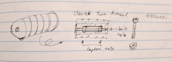
Sometimes as I’m doing a deep dive on a project, I have an idea for an improvement or a way to do something in a different way from the original. It’s around this point imposter syndrome kicks in and I wonder “Is this actually a terrible idea that was already discarded by others?” I am sure the main point of having a post / threaded rod / post sandwich for the turn around is to ensure there’s a length of metal running through the turn around. It’s probably even more important if the turn around is made of plastic. Then again, what if there was a 3D printed turn around which had two spots for captive nuts and there was space on either side for two long machine screws / bolts? It would probably have most of the strength of a solid piece of metal running all the way through, far easier to source (and in black oxide hardware!), and fairly easy to assemble. Printing in plastic allows such cool options, such as embedded / captive nuts, why not leverage that ability here? A sketch:
Turn around sketch for 3D model, using captive nuts
Ordering
I haven’t ordered all the parts, but it looks like the most likely route is for me to place an order with Home Depot and Amazon for the various parts. I’ll post links if/when I get the full shopping list together.
Tools
Drill and drill bits for the tuners and turn around
Hacksaw to cut out the rough shapes, possibly cut threaded rod if I was using that
Coping saw to cut the interior area out nicely
Nippers (left over from some tilework) to cut the cotter pins
Files and sandpaper for taking the rough edges off the cotter pins and shaping the neck
Process
Create template
Transfer template
Drill holes before cutting out the center, this way the wood in the center won’t splinter
Cut rough shape of ukulele
File, sand, and shape
Glue cotter pins
File, sand, and shape
Add tuners, bridge, and turn around
I guess the next step is getting these ideas off paper11 and ordering some stuff!
He references his research for this figure, but doesn’t mention where it came from. Perhaps it’s in his book? I checked it out from the library, so I’ll let you know. [↩]
I’m trying to find a good place to mention the Japanese word for the process of continuous improvement is “kaizen.” [↩]
Another great distillation of these ideas is that 1% improvement every day for an entire year yields a 37.78 times improvement overall. [↩]
This is the second post in a short series about vacuum formers. You can start with the first post about how to make your own inexpensive and easy to use vacuum former or skip to the bottom of this post with a list of all of the posts in this series.
Theory
This slideshow requires JavaScript.
I discussed the theory behind a vacuum former in the prior post. This post is really about how to actually use a vacuum former in conjunction with a heat source.
Parts
This slideshow requires JavaScript.
“Buck”
The things you’re going to create molds of with your vacuum former are called the “bucks.”
Wire coat hanger
The coat hanger will be bent out of shape and won’t be usable for hanging clothes after this. A coat hanger from your local dry cleaner would do just fine.
The good news is that this is the only thing, besides the consumable plastic plates, that you can’t put back into its ordinary service as soon as you’re done vacuum forming.
4 or more binder clips
Pretty much any size binder clips would work, as long as they can get around the thick gauge wire of the coat hanger. I only had four on hand, (which is probably the minimum necessary) but the more the better. As you heat the plastic, it will contract and deform. The more clips you have, the more circular you can keep the plastic as you lay it on top of the object.
Oven mitt
I used a cotton oven mitt that has a silicone rubber grip. This is probably overkill, but better safe than sorry.
Everything you’ll be touching with the oven mitt will be cool to the touch within about a minute of taking it out of the toaster oven. I’m pretty sure a thin towel which has been folded over several times would work just fine.
Toaster oven
Preferably one that can do small round pizzas. If you’re out shopping for one, try and find one that will fit the 10″ diameter plastic plates. You can find a cheap toaster oven for about $30 on Amazon and about $15-20 on Craigslist. If you’re short of funds, I’m pretty sure garage sales or Goodwill would have a bargain.
Out of an abundance of caution, I was using my toaster oven outside on the off-chance that heating the plastic was giving off some undesirable fumes. I’m also utilizing a used toaster oven donated by my brother. I’m pretty sure the process of heating a few pieces of plastic in the toaster oven don’t make it unsafe for cooking food, but again, I’m erring on the side of caution here.
There’s nothing special about the toaster oven; it’s nothing more than a convenient and cheap heat source. If you were a more daring sort you could probably use your standard kitchen oven. I suppose in a pinch you could also use a cheap heat gun, but I haven’t tried this yet.
Pliers (Optional)
I got these out to help shape the coat hanger. In the end, I didn’t use it very much and it probably wasn’t necessary.
Consumables
Round plastic plates, 10 – 1/4″
Round plastic plates (~10″ diameter, without dividers?)
These are just the bulk plastic plates we had left over from Party City. Next time I’m there, I’ll check and see just what kind of plastic they’re made of. Their website suggests they carry plastic plates with diameters from 9″ to 10.25″ to 10.5″. The plates I had were 10.25″ and they worked out really well. You can probably find a pack of 50 plates for less than $10. You might be able to do even better by hitting up a dollar store.
Make the Plate Holder
This slideshow requires JavaScript.
Using your hands or a pair of pliers, bend the coat hanger as pictured. The goal is to get it to fit around the underside of the rim of the plate.
Clip the Plate to the Plate Holder
This slideshow requires JavaScript.
Using four or more small binder clips, clip the coat hanger to the paper plate. Put two clips on either side of where the coat hanger handle meets the plate. Put the other two clips approximately 180 degrees from the first two clips. If you have more than four binder clips, they would be helpful since the plastic will pull away from the frame as it heats up. (I only had four on hand)
Turn on the Toaster Oven
Remove all the racks, except for the bottom drip tray, from the inside of the toaster oven.
Set up your vacuum former as close to your heat source as is practicable. You want to be able to transfer the molten plastic plate to the vacuum former as quickly as possible so that it doesn’t cool down in transit.
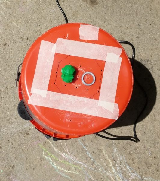
Prepare Buck and Turn on Vacuum Former
Vacuum former at the ready
Organize the bucks (the things you want to mold) on top of the vacuum former, then turn on the vacuum.
You may notice the vacuum pushes or pulls some of the objects out of the way. Just rearrange them as necessary. I try to place things so that they’re surrounded by the holes in the top of the vacuum former.
Basically, you want the vacuum pulling on the hot plastic plate, but not sucking air freely from around it. If the holes in the top of the vacuum former are spaced out way outside the perimeter of the plate, you’ll want to cover those holes up with some tape. Regular masking tape worked just fine for me.
Heat and Vacuum!
This slideshow requires JavaScript.
Put on your oven mitt, open the toaster oven, and hold the plate in the oven near the top heating element.
The plates I used went through several physical changes before they were ready. First they softened a little, then they actually flattened all the way out, then then pulled away from the wire frame, then, finally, the plastic got very droopy. This whole process took less than a minute with the oven at full power.
Once the plastic is nice and droopy, pull the frame out and place it on top of the vacuum former.
The vacuum should pull the hot plastic around your objects. After a few seconds the plastic should no longer be flexible and warm. Once it’s cool, turn off the vacuum.