OpenSCAD Intermediates: How to Make Complex Organic Shapes

Cyborg Beast OpenSCAD prototype

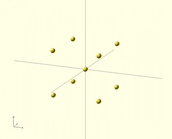
OpenSCAD tutorials for the MakerBot blog.  In that OpenSCAD tutorial series I covered the basics of the OpenSCAD interface, how to make 2D forms, how to make some basic 3D forms, how to position those forms in 3D space, the different ways to combine forms, how to create mashups of one or more existing STL’s and OpenSCAD forms, how to use modules to reuse your code to make your life easier, how to extrude flat 2D forms into 3D forms, and how to fix design problems.  One of the last tutorials was on how to make organic looking shapes using OpenSCAD.1  However, I have a few design tricks left to share.  A little over 18 months ago I left off the series suggesting as new topics.2 There’s one particular “trick” I am using a lot as I work on designing a printable parametric prosthetic. This trick is somewhat easier to explain using pictures.  Suppose you wanted to make a shape that looked something like a “jack,” but you wanted it to have curved surfaces at the center.  Let’s see what happens when we try to use the “hull()” command.  Do do this, we’ll make a sphere at the center and put eight more spheres around it.  The code for this example is basically irrelevant, but I’ll provide it anyhow.

sphere(r=10);
rotate([0,0,0]) translate([100,100,100*pow(2,0.5)/1.5]) sphere(r=10);
rotate([0,0,90]) translate([100,100,100*pow(2,0.5)/1.5]) sphere(r=10);
rotate([0,0,180]) translate([100,100,100*pow(2,0.5)/1.5]) sphere(r=10);
rotate([0,0,270]) translate([100,100,100*pow(2,0.5)/1.5]) sphere(r=10);
rotate([0,180,0]) translate([100,100,100*pow(2,0.5)/1.5]) sphere(r=10);
rotate([0,180,90]) translate([100,100,100*pow(2,0.5)/1.5]) sphere(r=10);
rotate([0,180,180]) translate([100,100,100*pow(2,0.5)/1.5]) sphere(r=10);
rotate([0,180,270]) translate([100,100,100*pow(2,0.5)/1.5]) sphere(r=10);

There’s a much easier way to create the 8 “orbiting” spheres, but that’s another post unto itself.  :)  Here’s what the above code will create:

Nine little spheres (I named one of them Pluto!)

Now, let’s use the “hull()” command to wrap around these spheres.

hull()
{
sphere(r=10);
rotate([0,0,0]) translate([100,100,100*pow(2,0.5)/1.5]) sphere(r=10);
rotate([0,0,90]) translate([100,100,100*pow(2,0.5)/1.5]) sphere(r=10);
rotate([0,0,180]) translate([100,100,100*pow(2,0.5)/1.5]) sphere(r=10);
rotate([0,0,270]) translate([100,100,100*pow(2,0.5)/1.5]) sphere(r=10);
rotate([0,180,0]) translate([100,100,100*pow(2,0.5)/1.5]) sphere(r=10);
rotate([0,180,90]) translate([100,100,100*pow(2,0.5)/1.5]) sphere(r=10);
rotate([0,180,180]) translate([100,100,100*pow(2,0.5)/1.5]) sphere(r=10);
rotate([0,180,270]) translate([100,100,100*pow(2,0.5)/1.5]) sphere(r=10);
)

That code will make this:

Nine spheres to... a box?
Nine spheres to… a box?

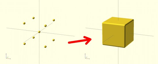
The result looks nothing like a jack! It looks more like a box with rounded edges. The limitation with the “hull()” command3 is that it connects all the outside points from the various shapes.  The result is more like what the objects would look like if you covered them in plastic wrap – but not what they would look like if you tried to use shrink wrap.4 However, our goal is to get a jack.  How should we go about this?  The same way we eat an elephant.56 We need to use “hull()” multiple times7 to connect the central sphere to the eight surrounding spheres.

hull() { sphere(r=10);
rotate([0,0,0]) translate([100,100,100*pow(2,0.5)/1.5]) sphere(r=10); }
hull() { sphere(r=10);
rotate([0,0,90]) translate([100,100,100*pow(2,0.5)/1.5]) sphere(r=10); }
hull() { sphere(r=10);
rotate([0,0,180]) translate([100,100,100*pow(2,0.5)/1.5]) sphere(r=10); }
hull() { sphere(r=10);
rotate([0,0,270]) translate([100,100,100*pow(2,0.5)/1.5]) sphere(r=10); }
hull() { sphere(r=10);
rotate([0,180,0]) translate([100,100,100*pow(2,0.5)/1.5]) sphere(r=10); }
hull() { sphere(r=10);
rotate([0,180,90]) translate([100,100,100*pow(2,0.5)/1.5]) sphere(r=10); }
hull() { sphere(r=10);
rotate([0,180,180]) translate([100,100,100*pow(2,0.5)/1.5]) sphere(r=10); }
hull() { sphere(r=10);
rotate([0,180,270]) translate([100,100,100*pow(2,0.5)/1.5]) sphere(r=10); }

The result would look like:

Much better!
Much better!

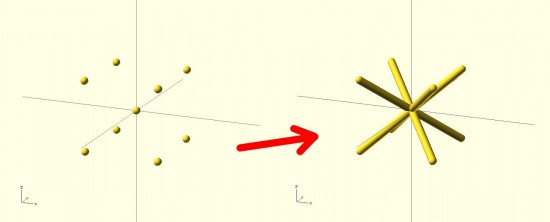
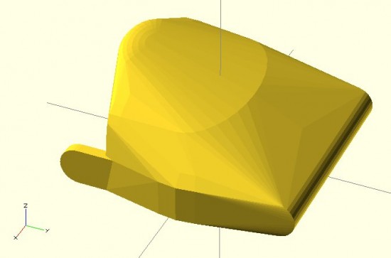
By breaking the overall design into pieces, you can use the “hull()” command to connect pieces of the design to one another in a seemingly organic fashion.  Here’s a set of pictures of my most recent work that uses these design tricks.

This slideshow requires JavaScript.

  1. Full list here:

    1. OpenSCAD Basics: The Setup
    2. OpenSCAD Basics: 2D Forms
    3. OpenSCAD Basics: 3D Forms
    4. OpenSCAD Basics: Manipulating Forms
    5. OpenSCAD Intermediates: Combining Forms
    6. OpenSCAD Intermediates: Mashups
    7. OpenSCAD Intermediates: Modularity
    8. OpenSCAD Intermediates: Extruding 2D Objects
    9. OpenSCAD Intermediates: Fixing Design Problems
    10. OpenSCAD Intermediates: How to Make Organic Shapes
    11. OpenSCAD Design Tips
    12. OpenSCAD Design Tips: How to Make a Customizable Thing

    []

  2. These are, in no particular order:

    • How to sketch an object with OpenSCAD
    • How to easily make regular solids – other than cubes and cylinders, like hexagons, pentagons, octagons, etc
    • How to easily make symmetrical solids
    • How to easily make irregular, but symmetrical solids

    []

  3. I almost typed “problem,” but in this case it probably is just a feature []
  4. That’s the best analogy I can come up with []
  5. One bite at a time. []
  6. It’s such a damn shame when a cool domain name is taken – and there’s nothing there.  Such as eatanelephant.com []
  7. 8 times []

Progress on Parametric Printable Prosthetic

This slideshow requires JavaScript.

So, I’ve been hacking away at an OpenSCAD sketch of the Cyborg Beast 3D printable DIY prosthetic.  At the moment I’m working on designing the left palm.1 I’m reasonably happy with the version so far.  I’ve also managed to separate out the cutouts for the hardware from the design of the hand itself.  The benefit to doing so is that it should later be possible to scale the hand up or down, but keep the hareware cutouts the same size.

It’s easy to print a hand, fingers, and thumb scaled to 110%, but finding Chicago screws that is 110% may be more difficult.  There’s still a LOT of work to do here, but I think this is a good start.  Below are the same three views of the two versions (OpenSCAD parametric and original Cyborg Beast).

This slideshow requires JavaScript.

As I’m going through and replicating the design aspects of the Cyborg Beast, more design issues crop up:

  1. The grooves where the fingers fit into the palm are either tapered or flared in a non-uniform manner.  To get a better idea of this by reviewing the two pictures below.
  2. The holes for the elastic cord to cause the fingers to return to the open position do not appear to be of uniform diameter, uniform distance apart, or equally centered in the knuckle blocks.

This slideshow requires JavaScript.

I can’t tell if these are critical design features2 or just design elements that don’t provide additional function or utility.  If you happen to know, your input would be greatly appreciated.

Default Series Title
  1. And, really, once the left palm is done it’s an easy to mirror this part to make a “right palm.” []
  2. I’m guessing not []

Measurements Required for DIY 3D Printed Hand Prosthetics

Cyborg Hand v7.0
Cyborg Hand v7.0

I’ve recently embarked upon a quest to create a parametric version of the e-NABLE prosthetic designs.  I’ve chosen the “Cyborg Beast” as it came highly recommended and I had the good fortune to meet one the main designers.

I have a habit of diving headfirst12 into a project I know absolutely nothing about and learning just enough to be dangerous as I go.3 Even if the results aren’t what would be called “successful” under normal circumstances, they do tend to be entertaining.

I generally get started by asking a ridiculous amount of questions.4 I have some guesses, but no concrete answers to the below.  If you know, I’d greatly appreciate any comments or replies.  Here’s a bunch to get us started:

  1. What are the minimum required measurements to create a suitable prosthetic, such as the Cyborg Beast?
    1. Knowing the minimum required measurements would allow a designer to better create a parametric design.
    2. The Cyborg Beast instructions refer the builder back to the measurement instructions for the Snap Together Robohand by Michael Curry aka Skimbal. These instructions indicate that all you need is the measurement of the width of the hand, where the hand is held flat with the fingers together, at the widest point on the knuckles.  Based upon the ratio between the subject’s knuckles and the stock Robohand knuckle block, all of the parts for the model are then scaled up or down.
    3. The ease of reference, the entire set of instructions for the Snap Together Robohand are as follows:
      1. Measure the length of the individual’s knuckles across the back of the hand

      2. from the index to pinky finger. (Example: 85mm)
      3. Add 5mm to your measurement to account for the thickness of the gauntlet.

        (Example: if the individual’s hand measures 85mm knuckle-to-knuckle, add 

        5mm for a total length of 90 mm).

      4. The knuckle block in the files you downloaded is 65mm. Divide your result by 

        65. (Example: 90/65 = 1.38).

      5. Multiply the answer times 100 to get a percentage. 

        (Example: 1.38 x100 = 138%).

      6. Scale all the parts of Robohand by this percentage before printing. This can b

        e done using the ‘Scale’ tool in Makerware.

    4. Are there any other measurements, besides the width of the hand at the knuckles, required to create a suitable custom prosthetic?
  2. How do these measurements inform a customized prosthetic design?
    1. Scaling all parts equally makes sense for a “snap together” design where all the parts, including the fasteners, are sized together.  When one is using stock parts (such as screws, elastic cord, and nylon cord)), this approach can end up requiring the builder to do a lot of post-printing work widening holes or trying to find wider screws.
    2. Other than scaling all parts equally, based upon knuckle measurements, is there any other modifications to the printable design required in order to create a useful prosthetic?
  3. How accurate do these measurements need to be in order to create a suitable prosthetic?
    1. Do the measurements need to be down to the micron?  Is within about 1mm or so good enough?
  4. For each required measurement, is it better to round it up or down?
    1. If the only required measurement is the width of the knuckles at the widest point, I suspect that it is probably better to round this figure up, rather than down.  I believe it would be much easier to add a little extra padding or tighten the velcro strapping a bit more.
  5. What are the important structural features of the Cyborg Beast?  As in, what parts, dimensions, and part relationships are absolutely critical to its proper function and fit?
    1. I’m very very weak in this area.  I just don’t know which parts are “load bearing” and are so critical to the function of the device that I should make special efforts to replicate them in my design.  Any suggestions here are greatly appreciated.
    2. I suspect that the critical functional features include part thickness (especially where separate parts meet – for strength and durability), the height and length of the “outcropping” on the back of the wrist which appears to provide the mechanical advantage which causes the fingers to constrict, and the tightening block on the gauntlet.
  6. What are the important design features of the Cyborg Beast?  As in, what parts, dimensions, and part relationships are critical to the suitability of this model over others?
    1. Again, I’m incredibly weak in this area.  I suspect that the overall organic shape to the model is one of its most stand-out features.  However, I would invite more informed comments and observations.
  7. What parts of the Cyborg Beast are the most improved?
  8. What parts of the Cyborg Beast are most in need of improvement?
Default Series Title
  1. Almost willy-nilly, if you will. []
  2. You will, won’t you? []
  3. I imagine this is what it is like to learn to fly. []
  4. If you don’t believe me, feel free to peruse this site where you fill find literally thousands of words on the smallest design variations on the smallest parts for a drawing robot []

Possibly Parametric Prosthetics

Cyborg Beast v7.0
Cyborg Beast v7.0

This last Friday I journeyed to the Autodesk offices at Pier 9 in San Francisco to attend a meeting for e-NABLE, a group devoted to developing, making, and distributing DIY prosthetics.  I have to admit that my own personal interests weren’t necessarily aligned with that of the entire group.  I’m sure those there would forgive my trespasses, but I am far more interested in making the prosthetics and in making it easier for others to make similar prosthetics than I am in the actual mechanics of building an organization that does these same things.

I came away from the meeting having met some amazing people doing amazing things, and with considerably more knowledge than that with which I arrived.1 Just as with the RepRap project, the daunting part of getting started in this field is wondering where the heck to get started.  There are so many different models being developed and so much information, that I just was not sure how to go about actually making such a prosthetic.

As frequent readers of this blog2 know, I like to treat this site as something of an online open notebook where I share my notes, thoughts, and ideas.  Thus, here are the most helpful things I learned as a result of this meeting:

  1. Where to Get Started
    1. Jonathan Schull, an associate professor at the Rochester Institute of Technology, was patient and kind enough to provide me with some pointers on where to get started with producing 3D printed prosthetics.  Jon suggested the Talon Hand for strength, the Cyborg Beast for general use, and the ODY Hand for young children.  The Cyborg Beast instructions refer one to the measurement instructions for the Snap Together Robohand by Michael Curry aka Skimbal.  The process, as far as I understand it, involves measuring the subject’s hand and scaling all of the parts up or down accordingly.
  2. Taking Measurements.
    1. Professor Jorge Zuniga, of Creighton University in Nebraska, is currently using a system for taking measurements that involves taking three photographs of a person’s upper extremities in different positions.  The photographs are taken with a ruler in the image, so that the measurements may be extrapolated.  In talking with Professor Zuniga, I learned that while this is a good way to get a lot of information very quickly (take three quick photographs), it can be labor intensive and time consuming to actually extrapolate the various measurements.
    2. It occurred to me that this sort of problem has actually been solved reasonably well.  Marty McGuire 3 and Amy Hurst created a system for using pictures of hands with standardized objects to extrapolate hand measurements for the creation of custom 3D printed objects.  In the case of their NickelForScale project, they used a photography setup and OpenCV to create custom rings.  While OpenCV isn’t exactly the easiest thing to dive into, one it was figured out could reap huge time savings in gathering the measurements necessary to create custom prosthetics.
  3. Customizing Printable Prosthetics
    1. The multi-step process of taking pictures of a subject’s hands, extrapolating the necessary measurements, calculating the scaling factor, scaling the files up or down, then printing seems fairly involved to me.  While none of these individual steps are actually that complex, it is entirely possible to automate much of this and lower the barrier to getting people involved.
    2. One interesting problem that is created by scaling parts is that certain parts of a design probably shouldn’t be scaled – such as the channels for routing cables or holes for the Chicago screws.4 This inadvertent scaling problem can be completely solved by use of a parametric modelling program, such as (my personal favorite) OpenSCAD.  The “trick” is to scale the model and distribute the various channels for routing cables and screw holes to the appropriate positions to match the new scale – without scaling the diameter of these voids.
    3. One of the really great things about the Cyborg Beast prosthetic model is its extremely realistic and organic appearance.  While OpenSCAD is definitely well suited to creating functional models, it is not as obvious how to create organic seeming solids.  Fortunately, MakerBot’s handsomest and most modest blogger5 posted a very comprehensive tutorial on creating organic solids with OpenSCAD.
    4. Last night I got started on creating a parametric Cyborg Beast model.  While I’m not going for a completely faithful translation of the Cyborg Beast into a parametric model, I’m shooting for a reasonable facsimile of the most important structural and cosmetic features of the Cyborg Beast.  Below is a screenshot of this work in progress.  There’s no thumb joint in this model yet, but it’s coming along.
Cyborg Beast OpenSCAD prototype

Obviously, there’s more work to do embellishing this model, including adding the thumb joint, hollowing out the underside, adding the knuckle stops for the fingers, and the voids for routing the cables and screws.  However, it’s not that bad for a little bit of quick OpenSCAD hackery.  After that’s done, the various other parts would need to be replicated in OpenSCAD as well.

Cyborg Beast OpenSCAD prototype with original Cyborg Beast overlaid
Default Series Title
  1. That is to say, a lot more than zero! []
  2. Both of you! []
  3. Don’t let the abandoned website fool you – he’s a busy guy moving fast making awesome things []
  4. Head’s up – Chicago screws have a slightly more common and slightly less SFW name []
  5. AHEM *cough* []

What are the minimum parts necessary for an Arduino?

Outside a MintDuino, a book is a man's best friend
Outside a MintDuino, a book is a man’s best friend

It was hard for a beginner like me to imagine that an Arduino actually requires a whole lot less than all the stuff you would see on an Arduino Uno.  Assembling a MintDuino – and slowly pulling parts out to see what was really necessary – helped me understand what was truly critical to its operation.

Inside a MintDuino, it's too dark to read...
Inside a MintDuino, it’s too dark to read…

I found it useful to know what the (near) minimum necessary components of an Arduino were so that I could build a small project directly around just the chip and whatever critical parts were absolutely required to run the circuit.1 I wanted to build the circuit as small as possible – not to save on parts or cost, but to make sure everything could fit into an Altoids tin.23

As a side note, there is a very definite monetary benefit to figuring out how to build a minimal Arduino compatible device.  A brand new Arduino will run you about $30 – whereas soldering a chip into perfboard with the least amount of parts required would probably only cost you about $9 or less if you source the pieces carefully.  While an actual Arduino form factor makes a lot of sense when you’re using off-the-shelf shields, it’s not nearly as important when you’re building a very simple or completely custom project that you don’t intend to take apart.  And, when you’re talking about leaving a chunk of electronics in a project, it’s a lot easier to leave $9 in parts inside rather than a $30 Arduino board.

Here’s what I found to be the (near) least number of parts and (basically) the smallest configuration for the programming MintDuino:

The (almost) minimum you need to upload an Arduino sketch

This is the “almost” minimum since the configuration above includes (1) a red power indicator LED and a 220 Ohm resistor and (2) a red wire, another red LED, and another 220 Ohm resistor for running the “Blink” sketch.  Once you remove those parts, you could still upload a sketch to the Arduino – but it wouldn’t be able to do anything.  You’ll notice that this configuration doesn’t even include the usual reset button for the Arduino.4 It’s not pictured, but you’d also need a way to communicate with the Arduino, such as a USB cable plus FTDI Friend or FTDI cable.

Here’s what I found to be the (near) least number of parts and (basically) the smallest configuration for running a sketch on the MintDuino:

The (almost) minimum you need to run an Arduino sketch

Again, I’m qualifying the statement with an “almost.”  This nearly minimum configuration above again includes a red wire, another red LED, and another 220 Ohm resistor for running the “Blink” sketch.  You could remove all of these parts and connect whatever else you wish the Arduino to do for you.  While the power LED indicator is useful to know that your project has power, I could see some situations where you wouldn’t want it – such as for a project that needs to work in the dark without drawing undue attention to itself.

Besides fiddling around yanking parts out of my MintDuino to see what would happen, I also found some interesting tidbits about building a minimum possible Arduino.  If your project is tight on space or you are tight on parts or budget, you might find some of the following useful:

I’m still very new to this whole Arduino thing, so if you notice something wrong here, please let me know so I can fix it.

My very next Arduino project is going to be something that fiddles with my television’s IR (infrared) control codes.  You can expect some definite wackiness soon…

Default Series Title
  1. Since I wanted to include a picture of the MintDuino inside and out, I couldn’t help putting a spin on this classic Groucho Marx quote. []
  2. I ended up using the Mintduino tin – and actually recycling some of its packaging into the project as well []
  3. What project am I referring to? Stay tuned… []
  4. I discuss this more below, but I don’t think you need the crystal and two capacitors for the “external clock” functions of the Arduino if all you’re doing is uploading a sketch. []

Arduino Adventures: What I learned building a MintDuino

A MintDuino
A MintDuino

My first real foray into tinkering with an Arduino began a few weeks ago with a MintDuino.  About two years ago I contemplated trying one out, but I never pulled the trigger.  This was due to a combination of decision paralysis, a very short attention span1 , and a plethora of other projects that were always vying for my2 attention.

Overall, I think this was a good place for me to start learning about Arduinos.3 The nifty thing about the assembly tutorial for the MintDuino is that it takes you slowly through the creation of an Arduino.  I learned a surprising amount from assembling this little breadboard Arduino – more so than I ever did by just making an LED blink on a regular Arduino Uno.

  • The first thing the tutorial does is show you how it converts the power from a 9 volt battery into the 5 volts that an Arduino would use.  I found this incredibly useful.  Even if I had stopped reading the tutorial at Step 7, I would have learned that with some capacitors and a “voltage regulator,” I could create a system for converting power from a 9 volt battery into something I could use in a different project.  Sure, I didn’t learn how these parts made that happen, but this was something I could put to use immediately, if I so chose.
  • The second thing the tutorial takes you through, at step 9, is adding a “crystal.”45  This wasn’t particularly useful to me – except that now I know how the Arduino is able to keep time.  While doing some ‘net research on what constitutes a bare-bones minimal Arduino, I discovered that it is possible to omit the crystal and two capacitors in favor of the chip’s internal clock.
  • The third thing I learned from this tutorial, at Step 12, is what appeared to be the bare minimum MintDuino setup required to run a program that was loaded onto the Arduino’s chip.6 Now, it’s possible to remove several more pieces and still have a working Arduino.  If you just had to have an Arduino with an absolute minimum of parts (I’ll get to why later) you could pull the red LED, the 220 Ohm resistor, the black wire going to the red LED.  The result would be a pretty minimal Arduino that didn’t have a status/power LED, but could blink a single green LED.  Remove the green LED, the red wire going to it, and the 220 Ohm resistor going to the green LED, and you have a really stripped down Arduino – that can’t do anything.  But, if you were to design your own Arduino project, you could build this minimalistic Arduino, add connections to whatever additional parts you needed, and solder it all together.
  • By the time I got to Step 17, I learned the connections to the ATmega328 necessary to program the chip with an Arduino program.7  This was interesting to me because it meant that any circuit that I wanted to design, but still have the capability of reprogramming at a later date, would have to have these connections.  However, it would probably easier to add a 28-pin socket or 28-pin ZIF socket to your project so you can remove the chip, reprogram it, and replace it without much fuss.  ((I mean, why add a bunch of wires you only need for reprogramming to a project when you can add a little socket?))

Overall, tinkering with a MintDuino taught me quite a lot about Arduinos.  Staring at an Arduino for the first time out of a box, it’s a little daunting.  There are a ton of little surface mount parts and pins and I had no idea where to start.  I had made an LED blink – but that didn’t seem to do much for me.

Having assembled a MintDuino, I already knew what a bunch of the parts already did – so I could focus on building on my knowledge from there. Having the breadboard handy meant it was easy to connect more wires and try out other sketches and configurations.  Lastly, I went back over my work from the first time I built the MintDuino and rewired it so that the little red, black and green wires didn’t have any slack.  This let me see better which wires when where – which meant I could concentrate on working with the other pins.

I mentioned earlier why I was interested in finding out the absolute minimum amount of parts necessary to operate an Arduino.  Well, more on this in the very next post…

Default Series Title
  1. Oh!  A squirrel! []
  2. Oooh!  A shiny! []
  3. I say “start” because my prior experience with Arduinos consisted of just putting shields on Arduinos and uploading sketches. []
  4. I don’t know why they call it a crystal – it just looks like a little bit of metal with two wires sticking out []
  5. I’m just kidding.  I’m guessing they’re using a quartz crystal – similar to quartz watches – as a timer/clock.  For those of you who aren’t familiar with quartz watches – they keep time by applying a little bit of electricity to a piece of quartz and counting the vibrations of the crystal. []
  6. The Arduino’s chip is called an ATmega328 []
  7. Or, in Arduino parlance, “sketch” []

Arduino Adventure Series – The Adventure Begins!

Arduinos, Arduinos, Arduinos... where to start?!
Arduinos, Arduinos, Arduinos… where to start?!

A few weeks ago I started fiddling with an Arduino in earnest.1 I’ve built things using Arduinos before, but each time all I did was slavishly follow a tutorial as it took me step by step through a process.

Just as a child memorizes the Pledge of Allegiance, committing to memory the right sounds in the right order, I had a grasp of the assembly – but not the underlying meaning.  Sure, I built a MakerBot Cupcake CNC (“Bender”), a MakerBot Thing-O-Matic (“Flexo”), an Egg-Bot, a Polargraph/PlotterBot, and an IoT Printer.  ((FYI, my MakerBot Replicator 1 is named “HedonismBot“))  However, I have only the dimmest understanding of how the things I did actually created the things I ended up building.

However, I want more – there are several ideas I would like to create using electronics.  One is a sonic screwdriver flashlight.  Another is device for … shall we say…2  interfering with television infrared codes.3

My goal for this series of posts4 is to document my triumphs and failures playing with an Arduino.  I think it’s time to get started on that next post now…

Default Series Title
  1. Photo courtesy of Arkadiusz Sikorski []
  2. Mu-ah-ha-ha!!! []
  3. Nope, not a TV-B-Gone []
  4. I know it’s ambitious to call a post the “first” post – but dammit, a man’s got to dream []

How to add a custom button to the WordPress Visual TinyMCE Editor

Adding a button
Adding a button

The other day I found a great post that explained how to add a custom button to the WordPress Visual TinyMCE editor.1 It was fairly simple and concise and even includes a zip file of all the parts you would need to install a button into WordPress’s visual TinyMCE editor.  I’m not at all sure I could do a better job than that guy, so I’ll just direct you to the link above.  :)

Default Series Title
  1. Photo courtesy of Marco Bernardini []

OCD Plugin Stats and the WordPress.org Statistics API

What you get when you don't use an API
What you get when you don’t use an API

The current version of my WordPress OCD Plugin Stats plugin, is somewhat… clunky.1 When I wrote it I didn’t know that WordPress.org had an API for it’s plugin statistics.2 Thus, the current version essentially scrapes particular WordPress.org plugin pages for information and drops it into the WordPress dashboard.

After poking into the stats on one of my plugin pages the other day I discovered that the source code for the page included several calls to a WordPress.org API.  Why should I bother scraping and interpreting a page of HTML when I can just ask WordPress.org to deliver the exact data I need in a nifty JSON format?!  I’m very much looking forward to adjusting this plugin to use a more direct and simple call to the WordPress API rather than scraping plugin pages.

In any case, if you’re looking for documentation on this, I found a page in the WordPress Codex and a site with a page devoted to documenting the WordPress.org API.

Default Series Title
  1. Photo courtesy of peasap []
  2. Apparently they have more statistics than just on plugins []

How to add a custom button to the WordPress editor

While posting about my DrawBot adventures, I’ve become increasingly annoyed with my own post series WordPress plugin.  If only it had a simple button in the WordPress editor to drop the shortcode for an existing series, it would instantly become so much better.  Thus inspired, I delved into WordPress.org and sought out the answers.  What I discovered is that while it’s not particularly difficult to add a button to the WordPress text editor, it didn’t seem to be very well documented.  I’m still working on how to add a graphical button to the WordPress TinyMCE visual editor, so stay tuned for that.  I was ultimately able to glean the necessary information from the WordPress “Quicktags API.  However, for your sake1 I’m distilling what I’ve learned right here.

First, I’ll give you an overview of what we’re going to do.  If you’re looking to add a button to the WordPress editor, it’s probably because you’re working on a plugin.  Thus, I’ll assume you have a working knowledge of plugin development.   Your plugin will need to include, at a bare minimum, one action hook and one function which performs the double duty of creating the button and giving the button some kind of ability.

// This action adds a script to the script footer on administrative pages
add_action( 'admin_print_footer_scripts', 'MBSS_quicktags', 100 );

// This is the function that is run at the end of the administrative pages in the script footer
function MBSS_quicktags()
     {
     // Optional database interactions
     // I used this section in my plugin to run a query on the database and return information that would be used in the button
     ?>

     <script type="text/javascript">
     // Creates button in the text editor
     QTags.addButton( 'MBSS_tag_id', 'Add Series', MBSS_add_series_js );
     // Function to append the series shortcode to the end of the post
     function MBSS_add_series_js()
          {
          editor = document.getElementById('content');
          editor.value = editor.value + "\n" + "EXAMPLE TEXT TO APPEND TO END OF POST";
          }
     </script>
     <?php
     }

And there you have it! One action hook and one function which adds some javascript magic to your WordPress editor in the form of a simple text editor button!

Default Series Title
  1. And, frankly, for my own future use []
Test