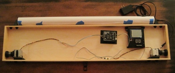
Unfortunately, it will be a few more days yet before I can completely finish the drawing robot. I still need to order some rainbow ribbon cable and connects, wire up the motors, and then actually draw something with the brand spanking new PolargraphSD brain. For now, please just ignore the mess of wires and the superfluous Arduino + Adafruit motor shield in the middle. The blue tape on the paper roll is just there to keep it from unfurling.
As you can see, the project box looks so much better without all the clutter inside. Once I’ve gotten everything all set up and tested, I plan to add some internal wire guides to keep the wires in check. That should help the whole project look a lot more clean and pleasing.
I’m fighting my perfectionist1 to keep printing and reprinting parts. I had the idea to have dualstrusion printed spools. I know from experience that rotating single color spools don’t look all that much different that from non-rotating single color spools. A spool with a dualstrusion pattern embedded in it would provide some kind of interesting visual confirmation that the robot was operational. Then again, I do like having a very monochrome project – unpainted, unvarnished wood, black ABS plastic, and black oxide bolts.2
You can see above that I’ve already drilled a rough hole into the right side of the box to route the power cable through. There’s just enough clearance in that hole to allow a USB-B cable to go through as well.
I’ve tried to use a very modular system that allows me to loosen and tighten parts in place with a single bolt. While making minor adjustments here and there, this system has been amazingly useful.
I’ve taken several more pictures of the various plastic parts and how they fit together. I’ll post about these shortly.3
Except the shiny M3x8 bolts used to mount the motors. I wish they didn’t bother me as much as they do. [↩]
Well, to be perfectly accurate, I’ll post about these plastic parts soon. If you’re a regular reader of the blog, you’ll note that few of the posts could be legitimately described “shortly.” [↩]
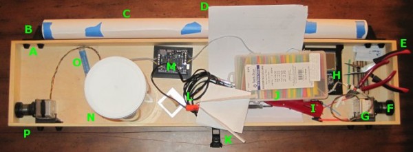
Above is a picture of my drawing robot, still a work in progress. The great thing about this particular project box is that it also doubles as a work area. It’s a good place to cut and strip wires, solder, assemble parts, and it’s totally portable. The box is 3′ long, 8″ high, 2″ inches deep.
A. Printed Bolt Covers. An M3 nut goes into the recess and the end of the bolt is covered by the printed part. One of these goes over every one of the protruding bolts in the project box.
B. Printed Paper Roll Mounts, on a Slide. These are actually three separate printed parts. Since the paper roll came without a cardboard tube, I put a wooden dowel down the center, with printed plastic caps on either side to hold the paper in place. There are two printed holders which the wooden dowel slot into. Each of the printed dowel holders slide left and right on a track and have a bolt that can be tightened to keep it from moving.
C. Paper Roll. After looking in a few craft stores I finally found a big long roll of paper at Staples of all places. I think it was marketed as paper you would use to cover a table. It’s thin paper, but there’s a lot of it and it was really cheap. With no internal cardboard tube, I had to design endcaps to keep it from wobbling all around.
D. Maker Faire Application. I’m hoping to display this robot at Maker Faire Bay Area 2013. Since the call for Makers hasn’t gone out yet I just downloaded the Maker Faire New York 2012 application and filled it out. Now when the call for Makers comes, I’ll be ready.
E. Wire Cutters and Pliers. These are just necessary tools. When I need something to hold tiny parts I wrap a rubber band around the pliers and they’re a tiny vise.
F. Printed Spools. Two printed plastic parts plus three nuts and bolts. Definitely overengineered, but they don’t have the weaknesses of a single print spool.
G. Motor Bolted to Motor Mount, on a Slide. The motors are bolted to a plastic mount with a groove. The motor mount is then slotted onto the slide which is itself bolted to the actual project box.
H. PolargraphSD in a Printed Case. I designed and printed the case. The way it is mounted to the project box, it is slightly offset from the box, which gives the circuit boards extra ventilation.
I. Stick Lighter. I used this stick lighter to heat the heat shrink.
J. Heat Shrink. Lots of heat shrink in varying colors and diameters.
M. Adafruit Motor Shield on an Arduino Uno, in a Printed Holder. Well, that about says it all. I would point out that the printed holder is pretty terrible – it’s just a little too small. The only reason I put the Arduino and shield in the box was so that I could hook up the motors and make sure everything was still in operating condition.
N. Big Container of Zip Ties. Zip ties are useful.
O. Solder. For soldering.
P. Monofilament Guide. You can’t see it, but there’s a little plastic tube that fits into a hole drilled through the wood project box. It’s much smoother than wood and works great.
I’ve taken a lot of detailed pictures of the various parts and how they go together, so that comes next.
Electronics. The electronics are the brain and heart of this project. There’s really only two parts that could not be found or scavenged – these parts being the Arduino and the Adafruit Motor Shield.
Adafruit. I’m going with Adafruit all the way. Great website, great blog, great service, and their tutorials are super comprehensive.
These were the exact items I bought. To date I still have never hooked up the servo motor to anything, but I hope to soon. I could probably have substituted these smaller cheaper motors and used a left over power supply from some random project, but I knew these parts worked for others and would probably work for me.
If you were really just had to build a similar robot for as cheaply as possible, you could probably pull a pair of steppers and possibly a servo from some old printers, copiers, and the like.
Project Box. I’m using a long thin pine box left over after a huge catering party platter order. Frankly, you could mount the parts on nearly anything – a 2×4 or a nice custom box – it’s entirely up to you. Heck, you could even screw these parts directly into a wall if you were feeling particularly adventurous.
Structural Parts. Besides these main components, it’s really really useful to have a 3D printer to manufacture all the parts necessary to make it all work. Motor mounts, spools, etc. If you had a laser cutter or a ton of quick-set plastic, you could probably fabricate perfectly serviceable parts. The parts I’ve designed are ideally suited for my own project, could be modified for your own project, or you could just design some parts from scratch.
Hardware. There are also all the little bits of hardware to hold everything together. I still have a ton of M3x16 bolts and M3 nuts left over from building a Cupcake CNC and Thing-O-Matic. Besides these M3x16 bolts and M3 nuts, I did use two screwhead M3x16 bolts to hold the Polargraph case in place and eight M3x8 bolts to attach the two motors to the mounts.
McMaster has a truly amazing website. Even if you want to build a drawing robot and have zero parts on hand, you could pick up all the hardware you need from them super-cheaply. Update: The only thing I don’t care for about their website is that they don’t have a way of getting an estimate on shipping. Among McMaster’s virtues is their amazingly responsive customer support. I just asked them for a shipping estimate on these parts and they got right back to me. You could pick up a set of 100 nuts, 100 M3x16 bolts, and 100 M3x8 bolts for about $6. This is an absolute bargain for way more nuts and bolts than you’ll ever need for this project.
Yesterday I spent six dollars on eight lousy M3x8 bolts. Had I simply waited for McMaster, I could have had 100 M3x8 bolts for only $4.84
Chances are if you really had to you could use whatever bits of hardware you can find lying around your place. I’ve seen examples of similar drawing robots using zip ties to hold the motors in place.
Electronic Bits. I still need to track down some rainbow colored ribbon cable and connectors. While I do actually have all the pieces of scrap around my home to finish the robot right now, I don’t want to do this half-way. I want to use a rainbow ribbon cable because (a) I need to extend the motor leads to reach the circuit board, (b) it would be very helpful to have each lead color coded separately, and (c) they’re really pretty. As for the wire connectors, all the other parts to my setup are very modular and it would be very nice to have the electronic connections just as modular. After searching around, I found that Sparkfun has all the little pieces I need to finish this project.
Sparkfun. I’ve never really bought anything from Sparkfun before – but people I trust have spoken highly of them. I say never “really” because I bought into the Makey Makey kickstarter and they used Sparkfun to fulfill their orders.
4″ of 4-pin jumper wire for $0.95. My plan is to simply cut this female/female ended connector in half, solder each half to one set of motor leads, and then use normal headers to connect to these.
I’m completely confident that you could pull plenty of wire out of old electronics. They always have a ton of wire and connectors inside.
I recently had a very unsatisfactory experience trying to source some parts locally, so I”ll be placing an order for some ribbon cable and jumper wires from Sparkfun.
This post could also be entitled, “Customer Service Fail Day.”
TLDR: If you’re looking to build something, don’t even bother going to Radio Shack or Fry’s Electronics.1 Even in the SF Bay Area they won’t carry what you need and if you leave feeling disgusted with their customer service, you’ve gotten off lightly. Buy your parts online from someplace awesome like Adafruit or Sparkfun or someplace else that truly cares about what they do.
TLRA:2 Today I went looking for the last few parts I need to properly finish up my drawing robot. If I was able to locate these parts, my ‘bot would be totally ready to place on a wall and start drawing. Even at the risk of overpaying for a minor part or two or spending way too much time trying to locate a mostly inconsequential part, I wanted to try to finish everything this weekend.
I really should not have bothered. I should have just stayed home in my jammies, surfed the net for the parts I needed, and then waited a few days for them to arrive. If I sound disappointed, it’s probably just because I am. I went looking for some fairly basic parts:
Eight (8) M3x8 bolts
Multicolored ribbon cable with at least 4 conductors3
I would have been perfectly happy to substitute nearly any of these items for something even remotely similar. I would have settled for single color ribbon cable, bolts anywhere from M3x6 – M3x10, and really any kind of male and female connectors that would work. However, all of this is besides the point.
The first stop was a national chain hardware store.5 I honestly wasn’t sure I wanted to visit this store again,6 but I had a $5 coupon and I was pretty sure I would find the metric bolts I needed. On a recent trip to the local hardware store I rooted around their nut/bolt area only to discover that someone or someones had mixed many of the M3 and M4 bolts. It was such a mess that I didn’t want to try them again. I paid a lot more for the eight bolts than I was expecting to, but at least I found the exact number of the exact bolts I needed with no additional hassle. While I was there I also picked up an inexpensive 15′ white extension cord so that my ‘bot could have an extension cord of it’s very own.
The next stop was the local Radio Shack. I haven’t been to a Radio Shack in a really long time – mostly because I’ve had such unsatisfactory experiences there. However, given Radio Shack’s long history of being THE place for Makers to find parts and supplies and their apparent return to their Maker-roots, I was willing to give them another shot. The local Radio Shack is in the middle of a run down strip mall nestled between a Chinese take-out place and something else I don’t recall. I honestly thought the Radio Shack was closed until I got right up to it. As I walked up I held the door open for an older Asian lady. She walked in ahead of me and told the clerk, who was on his cell phone, that she needed to borrow $10. Assuming that these two people knew each other, I just went ahead and looked for where they keep components. Electronic toys up front, phones on the left, tablets and computers on the right, and towards the back under the television blaring some sports game7 I figured I might find some electronics components. The “aisle” was probably only about six feet long and about four feet high. Towards the entrance there were a few Arduinos and books8 on the left, speaker wire on the right, and at the back of the aisle9 on the left was a set of pull out drawers with various bits and bobs that could be used in electronics projects. Except none of it was what I needed. The other employee, a woman, walked over and asked if she could help me. I explained that I needed some ribbon cable and connectors, then I had to explain what they were. Once I had done so she pointed to some colored single-conductor wire. I tried to explain that a ribbon cable had more than one wire in it – and this time she pointed to the same single-conductor wire and then another set of single-color wire of a different color. Seeing that this was completely futile, I asked about connectors. Quite helpfully, she pulled open the drawer marked, “Connectors” and told me that any of them would work. I explained that I needed something I could solder to the wire I was hoping to buy and then be snapped together or pulled apart as needed. She picked up a random baggie of plastic and metal and told me that all the parts were in there. I told her I needed male and female parts. “Yeah, it’s in there.” Since she was pointing to a wire crimp with an eye terminal, I knew that either she had no clue what she was talking about or that she just didn’t give a damn about what she was saying. I honestly cannot understand how that store can justify having two employees at that location at any time, let alone at 2pm on a Sunday afternoon when I was literally the only potential customer around. There cannot possibly be enough consumers of radio controlled cars to keep the lights on in that store. The selection of parts was just abysmal and the service could only have been worse if the staff cared enough to actively insult me. After rooting around in the component drawers for a little, I gave up and walked out. Two employees and neither of them said a single thing as the only potential customer they might see that day walked out the door.
My third stop was to Fry’s Electronics. The parking lot was packed and the store was busy. What I love about this place is the parking lot is ALWAYS packed and the store is ALWAYS busy. It doesn’t matter if I come by first thing in the morning, or in the middle of a weekday, or a Sunday afternoon – it’s nearly impossible to find a parking spot and there are tons of people in there.10 While their staff aren’t always super helpful, I’ve found that about every other employee is actually somewhat knowledgeable about their wares. I walked into the store, past the bargain bin items, took a left at toys, and walked on towards PC components. Since ribbon cables and connectors are the sorts of things one would find inside a PC, I figured this would be the place to start. At the podium stood three young men dressed in black pants and white shirts wearing name tags – I assumed they worked there. The three of them were talking to one another and continued to do so as I stood in front of them. Finally, I said, “Hi!”. The three of them looked at each other and one of them, after several seconds what seemed like a nonverbal game of chicken to see who could go the longest without acknowledging the customer, one of them finally asked how he could help. I explained I needed ribbon cables and connectors. He showed me to wire and speaker wire.11 I explained that ribbon cable involves having multiple strands of conductors attached together to form a sort of “ribbon” of wires that ran together. He must have been spying on me at Radio Shack since he ran through the process of pointing to colored wire, then showing me two different colors of wire. After holding up a thick piece of electrical cord involving two-conductor wires each separately shielded, but attached by plastic, and miming what it would look like with many more wires along side it – but not as thick, he seemed to understand what I was talking about and took me towards some computer ribbon cables and connectors. After an afternoon of searching I felt that I had finally arrived at the right spot. I asked about male and female connectors or perhaps some male and female headers or anything of the sort he looked back over his shoulder towards his comrades and gestured vaguely towards the wall of parts in front of me and suggested I could find what I needed there. I asked him a few more questions while I rooted around for something that could work. Finally he asked if there was anything else I needed. I could tell there was no way this guy was going to help me any further so I thanked him and let him go. I ended up buying some male headers and a set of 4 pin connectors.
Here’s what I’ve learned from my experiences today:
Radio Shack is a big fat waste of time. I wouldn’t even buy a remote controlled toy car there.
Fry’s Electronics is a big fat waste of time – unless I am in need of an off-the-shelf computer component and require zero assistance.
Buying parts online for a better price is absolutely, positively, worth the wait.
The name of the store rhymes with “Orchard Supply Hardware” [↩]
About two months ago I went there looking for a replacement faucet spray head for our sink. They were out of stock and said it would be in stock in two days. I returned in two days and they didn’t get it in. I was told they would have it in the following day. So, like a moron, I came back. They still did not have it. I went to the local Ace Hardware and they had five of them just sitting on their shelf. DONE. [↩]
I’m still working on building out an awesome drawing robot.1 I’m designing printable parts to be installed into a left over wooden box for holding a paper roll, filament spools, stepper motor mounts, and a few more bits.
You may3 be wondering why I’m waiting to upload all of these parts. The simple reason is that as I design and install each part of the overall robot, I find that a given part might need to be redesigned or might be better design in another fashion. I’d hate to have someone print up some lousy parts and be stranded with a bunch of junk.
The ‘Bot So Far
Right now the robot sits a few feet away from me almost totally assembled. I’m really excited about it. I’ve mounted the PolargraphSD brain to the right side of the project box so that it would be easy to run the power cord to it. While I do like the Platonic ideal of the perfectly symmetrical robot, my more practical Aristotelian side won out. The upshot is that the leads I originally soldered to one of the motors is totally unnecessary and the leads I originally soldered to the other motor are woefully inadequate.
There’s not a lot left to do. Once the motor leads are extended and the robot mounted to a wall, it will be totally ready to go. I’ve realized that the slides I’m using to mount the paper roll are long enough for me to attach a set of wall mounting brackets.
Revisions to Existing Parts
Filament Guides. I designed these 2mm too short. While this almost certainly wouldn’t be a problem, these pieces are so easy to print that it just doesn’t make sense to live without the benefit of a part that works better. If they’re too short it is possible for the monofilament line to rub against the wood of the project box – which defeats the purpose of having the filament guides in the first place.
Recommended Changes to Existing Parts
PolargraphSD case. It turns out that just above the two Stepsticks in the PolargraphSD there are a pair of three headers with a jumper on each. The lid for the PolargraphSD case I designed didn’t adequately take into account their dimensions, which kept the lid from closing cleanly. I used a pair of wirecutters and then needlenose pliers to just rip the unnecessary bits of plastic out. You would barely notice the change unless you knew4 where to look. I’m not going to bother to reprint this part because that’s a lot of time and plastic to use for a feature that really doesn’t matter and is barely noticeable. I’ve updated the OpenSCAD code for this part, so anyone who prints from the latest revision would automatically benefit from this change.5
Spools. For instance, ideally I would have printed the two spools with a slightly smaller radius on the edges of the spool. As they are now they tend to bump a little against the bolts holding the motors into the motor mount. Making it just 1mm shorter would do wonders. There are a few easy fixes for this. The one I’m using for the moment is to just raise the spool on the motor shaft so that it doesn’t bump into any of the bolts. I should point out that this wouldn’t be a problem at all if only I had plenty of short M3x8 bolts. Right now I’m using M3x16 bolts with three nuts on them to hold the motor to the motor mount. This means the bolt head and the nuts get slightly in the way of one of the ends of the spool. Just using shorter bolts would instantly fix this problem. I’ve also sanded the end of the spools that fits onto the motor shaft. If I put more elbow grease into it, this would also fix the problem – but why bother when I can just raise the spool on the motor shaft for now and pick up some short M3 bolts later?6
Bolt End Caps
Today I installed the motor mount slides in the project box, the spools on the motors, the motors into the motor mounts, the motor mounts onto the slides, and the filament guides into the project box. When I finished all of this I realized that the ends of the bolts were sticking out. In the spirit of overengineering, I created little plastic caps to prevent the bolts from being able to scratch or catch on anything. While not strictly necessary, they do serve some useful purposes and and more aesthetically pleasing than having bare bolt threads sticking out from a chunk of wood. They’re not much more than a tapered cylinder with a hexagon shaped hole for a nut and a cylindrical hole for the bolt threads.
PolargraphSD Case Holder
Although I’ve designed a nifty PolargraphSD case, I can’t bolt the case to my project box because of certain design choices.7 The overall design I’m using for this robot involves a large paper roll mounted to the top of a box, with the paper to unfurl behind the box, and then down onto the wall. Since the back of the box has to be completely flat, I can’t put any bolts through the back. Thus, I had to design a way to mount the PolargraphSD case to the inside of my project box – all without putting anything through the back of the box. I could have designed around this by just adding vertical mounting tabs to the PolargraphSD case, but it just didn’t occur to me at the time. And, as suggested above, I’m not interested in reprinting the entire case just to add a small feature here and there. So I designed two tabs that the case could be mounted to and which, in turn, could be mounted to the top of the box. Overall, I’m really happy with the way it turned out.
Stepper motor mounts – discussed in this post – waiting to upload…
Filament guides – discussed in this post – waiting to upload…
Pen holder/gondola – TBD
The most difficult part is definitely going to be the pen holder. I’ve seen some good ones, but… well, that’s another blog post. :)
Motor Mounts.
I’ve designed these motor mounts using the same exact groove system that I used to mount the paper roll holder. This means I’ll be able to adjust, mount, and dismount the motors by just adjusting a single bolt. I’m a little concerned about whether the plate the motors are attached to is thick enough to prevent it from wobbling.2
I’ve also left space around the motor so that I can add some kind of insulating material. I’ll try a few different materials, starting with the cheapest and most readily available – cardboard. After that, I’ll try polar fleece, foam packing material, a sheet of rubber or silicone.
With some minor modifications to the design, I could use some zip ties hold down the motor.
Since I don’t have any really really short M3 bolts, the length which would be ideal for holding the motor to the mounting plate through a thin layer of material, I’ll use an M3x16 with several M3 nuts on it.
Filament Guides.
In my earliest version of my drawing robot I tried to use a plastic filament guide which was incorporated into a motor mount. While a cool idea, the original just didn’t work. The filament squeaked and tended to bind on the filament guide. This may have been due to the filament rubbing against the wood of the project box. This new one is basically a plastic cylinder that will be insert into a hole in the wooden project box.
ToDAY i’ve tinkerED with my DigiSpark From dIGIsTUMP and run it throUGH A few little programs.1 My experienCE with arDuinos is acTUALLY quite limited. SincE i’M faMILIar with c-style proGRAMMIng languages, I can teLl what an ARDUINO sketch is Doing if i spend enough time staring at the COde. I staRted off with “Blink,” then cHAnged it tO blink fASTEr, then FOUnd some COde for FLIppING CapsloCK on and off.2
WhAT i like about the dIGIspARK IS that IT IS so small I can keep IT IN THE coffee Table drawer nearesT MY Laptop to tiNKER with WHenever I THINK OF something to TRY. TherE ARE SOMe interesting littLE FEATURes to the DiGISpark from the arduino i’LL cover IN another posT THAT doesn’t look liKE it was typeD BY A chimp.
The MOST FUnctional pARTS of TODAY have BEEN devoted to PLAYing, MAKING tangram dESIGNS, bloggiNG ABOUt robot pART design, fiddling with a tiny miCROcontROLLER, and, of course, A NAP. HOW Did you spenD Your super bowl sunday?
After several iterations, I printed the parts2 for spools for the newest version of my DrawBot. ((Photo courtesy of Cory Doctorow))
The original spools I designed were simultaneously over-and-under engineered. They were over-engineered since, for spools, they required two separate parts that would be friction-fit together around the monofilament line. They were under-engineered since, ultimately they once came apart while still attached to the robot – resulting in a lot of monofilament line unspooling everywhere. While not tragic, it was a small hassle.
The second iteration of the spool for my DrawBot was far simpler. You feed the monofilament line through a tiny hole in the spool and slide it onto the stepper motor shaft. It was a single print where one end of the spool was flat and the other end was beveled to comply with the “45 degree” rule. This spool design worked wonderfully – once I forced them onto the stepper motor shaft. They were also bubble gum pink, according to my daughter’s specifications. However, once I decided to upgrade my DrawBot into a PolargraphSD, I needed to remove the motors from their mounts – which meant I needed to take the spools off. Unfortunately, taking the spools off proved to be a problem. I had to literally hack them off using some heavy wire cutters, pliers, and a no-foolin’ hacksaw blade. It did not help that I printed them at 100% infill. I cannot imagine for the life of me WHY I wanted to print spools, that are basically non-weight-bearing, in solid plastic. The big problem with this design was that the tolerances on the spools were not right – and it is entirely possible they never would be. Slightly too tight and they would have to be destroyed to be removed or adjusted and slightly too loose and they might not stay on the shaft or have too much play as the robot operates. In the end, I’m just not sure I could really “trust” a single-print press-fit spool to be removable and reliable.
Which now brings me to the spools I have designed over a few days and printed yesterday. After several revisions I now have two spools3 which are themselves compromised of two parts. I would have to say that although this spool is more complex than the first version I used, it is probably going to be the most reliable overall. Each spool requires 2x M3x16 bolts, 1x M3x12 bolt, and three M3 nuts. The two M3x16 bolts hold the top and bottom parts of the spool together tightly and the single M3x12 bolt is used to tighten the spool to the motor shaft. The result final result are two spools that are symmetrical, do not have a beveled end where monofilament can be gathered over an increasing diameter, and can be tightened on the motor shaft or removed with ease. They’re also somewhat heavy which gives them a good respectable “this-is-definitely-a-robot-part” feeling.
I will be sharing these designs on Thingiverse and they will be able to be found under my Designs or tagged with DrawBot, but I’m going to wait until after I’ve assembled the entire robot and have actually drawn something. For all I know these could be abysmal failures.
This weekend I worked on my DrawBot. ((Photo courtesy of Relly Annett-Baker)) I stripped my current DrawBot for parts so that I may build it back together with a PolagraphSD brain/heart. ((Bart? Hain?)) Given that there aren’t a ton of parts involved, the process went quickly. I disconnected the two steppers, pulled all the screws1 and all the nuts and bolts2 from the project. Right now all that is left of my once mighty3 drawing robot is an Arduino and shield duct taped to a chunk of plywood.
To assemble the new robot into the desired configuration ((Sketch D for those of you playing along at home)) I needed to design:
This new case is about 2/3 the volume of Sandy’s design and has vents along the sides and top to help with heat dissipation. It can also be assembled without any tools or hardware – with the LCD actually keeping the entire thing together. At this point I now have three perfectly serviceable cases. My goal, once the entire robot is put together, is that it look and feel like a finished and polished project – a DONE project. But, really, I’d like to have it semi-permanently installed somewhere in my house as a drawing appliance. My prior ‘bot while cool with tons of nifty little hacker cred to it was little more than a chunk of plywood with bits hanging off. I’d draw something with it, put the board away, then bring it out later.
My ideas for building out the robot have changed slightly since designing this case, so I might need to adjust the code and print another one. The issue now is that the case is designed to be mounted by being bolted into the base of the project box. However, if I do that a nut or bolt will have to stick through the back of the project which will prevent the paper roll from being able to travel behind the project box. I figure I could print a new case and bolt it to the side of the project box – but that might interfere with the location of the motors/motor mounts. I might be able to just ziptie the case to the top of the project box – which might not be good as the bot is expect to shake a little in operation and I don’t want the board shaken unnecessarily. Frankly, at this point, I think I’ll get everything else situated completely within the project box and come back to figuring out how to mount the case.
Although, an idea which just occurred to me is that I could glue some plastic mounts, with captive nuts, into the inside of the project box and bolt the case into that. Again, this would best be done once all the other issues are resolved.
New monofilament spools
I had to completely destroy my existing spools to get them off the motor shafts. For some god-awful reason I printed the two spools at 100% infill creating the sturdiest monofilament spools in existence. I cannot imagine what possessed me to do this. They were heavy and impossible to remove cleanly from the motor shafts. I didn’t get the tolerances right with the prior spools, so I had to force them onto the shafts – but then they were stuck. I had to use a big pair of wirecutters to chop chunks of plastic off until I could pull the last bits free from the motor. When I finish designing and printing a new set of spools, I’m going to make sure the tolerances are right before I assemble. I want the spools to fit snugly becuase I don’t want the motor to slip when it reverses directions – as it will do frequently across a large drawing.
I’m still kicking around ideas on how to improve the spools. My first spools were way too complex and the friction fit wasn’t enough to keep them together. My second set was too tight and too short. While I wouldn’t mind a friction fit spool, I need a spool that can’t come apart during operation4 , can be tightened on the motor shaft, and can be removed easily if necessary. Additionally, I’d like the final spool to be taller – so that there is more of the spool center and less of the flared end of the spool for the filament to wind onto. The flared end was flared so that the spool could be printed as a single piece. While this was nice for simplicity’s sake, I found that sometimes the filament line would “ride up” the flared end – which introduces unnecessary error into the process.
Looking at the AS220 Labs website page for their drawing robot kit through Archive.org, you will notice that they use a tall spool with a low-friction monofilament line guide. The benefit of the tall spool is that it can keep a more consistent diameter for more of the filament versus a narrow spool that will accumulate layers of filament more quickly. The benefit of the line guide is that it forces the robot to maintain the proper distance between the two motors even when the spools are mounted horizontally. I also happen to like the horizontal spool mount system since it means the motors won’t stick out from the wall quite so much.5
Besides tearing my drawing robot apart, this is the one thing I did manage to design, print, and put together over the weekend. Since the paper roll I’m using did not come with a center of cardboard or wood or on any kind of spindle, it is not an immediately mountable thing. My roll of paper is just that – a really long roll of paper.
What I wanted was a modular way to mount a roll of paper to the top of my project box so that it could be adjusted to fit different diameters and widths of paper rolls. My solution was to print two “caps” to go at either end of the paper roll, with a hole through them to run a long wooden dowel. The nifty part is where I then bolted two printed plastic tracks to the top of my project box, onto which I can slide a plastic arm which the wooden dowel fits into. Once the two plastic arms are in place, they can be tightened down onto the plastic track. The result is a rock solid paper roll mount that lets the paper roll freely turn. I was so happy with the way this turned out I almost couldn’t see straight. Yes, it is just a mount for a roll of paper – but it is the most solid and polished way one might hope to mount a core-less roll of paper on top of a wooden box.
A new way to mount the stepper motors to the project box
Given the amount of time I’ve spent just mounting a roll of paper and obsessing about spools, is it any wonder I haven’t finished thinking about how to mount the steppers? With the first incarnation of my drawing robot I had designed and printed no less than three completely different motor mounts.
I would like the final version of the motor mounts to be easily adjustable, probably using a similar track/mount system that I used to mount the paper roll. While this kind of solution takes more time to design, the result is a robot that can be quickly and easily improved and adjusted. As suggested above in the spool section, I am leaning towards mounting the motors so that the shafts are horizontal on the plate of the wall. This will let the motors keep a slim profile in the project box and allow the use of a tall spool which will enable more even and uniform reeling and unreeling of monofilament.
I’m tempted to incorporate a monofilament line guide directly into the motor mount. In the interests of modularity, it makes sense to keep these things separate, but it might just make sense to do this given the limited space I’ve got within the depth of this shallow project box.6
I’m undecided whether I want to put a cover on the front of my project box. On the one hand leaving the front of the project box open allows the viewer to peer into the robot and marvel at its simplicity. On the other hand, without viewing the internals all you would see is a box mounted on the wall, a paper roll on top of that, a power cord coming out of the side, and a drawing pen moving by two almost imperceptible monofilament lines. Perhaps I should explore this idea in another long winded post?
When one of the friction fit spools failed mid-drawing, it was like watching my robot puke monofilament line. Frankly, a monofilament puking robot is pretty awesome – just not when it is made from a drawing robot [↩]
If you were betting on me not being able to type an ENTIRE Page of text just on the considerations of the spools in my robot, you would have lost. [↩]
For reference, the box I’m using is less than 2 inches deep. [↩]
I’ve been refreshing my DigiSpark Kickstarter backer/order page for days now watching my spot in the queue go from #3800 to just now under #200. ((Photo courtesy of Clarence Risher))
Since I have such limited experience with Arduinos, I am hoping that this project is a good place to start. To date my experience with Arduinos had to do with the minor modifications/updates with the Arduino powered motherboard and extruder board for the Cupcake CNC and my DrawBot.
One of the benefits of the DigiSpark that interested me the most was it’s extremely small form factor. It’s so tiny that I can pop it into a USB port and try out a small Arduino sketch1 without tangling with a USB cable. And, when not in use I can drop the whole thing into the coffee table drawer. An Arduino plus USB cable, while still small, are just a little too bulky to toss into the same drawer. ((Mostly because of all of the other little projects I already have tossed in the same drawer!))