DrawBot Pen Holder Post Mortem

Yoda, standing tall

Yoda, standing tall

Two days ago I designed a new type of pen holder for my drawing robot based upon what I had learned from examining the pen holders other people have designed and used.

Here’s what worked and what didn’t:

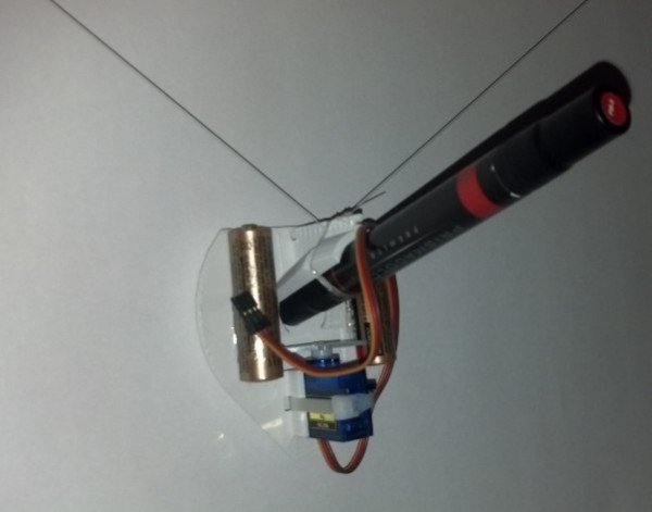
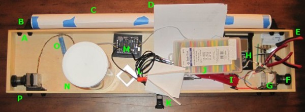
  1. WORKED:  The fit.  I’m really happy with how the pen holder went together.  It’s always very satisfying to print a part you just designed and have it “just fit.”  With the zip tie holding the micro servo in place, neither the micro servo tab nor the zip tie protrude beyond the flat surface of the pen holder.  The groves for the rubber band to hold the pen in place work very well.  The pen doesn’t move side-to-side, get pushed back into the holder, and it is very easy to reposition the pen or change pens entirely.  While it’s not as elegant as, say, a metal spring, it works very well and doesn’t require a bunch of moving parts.
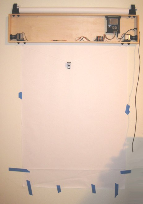
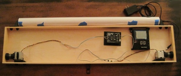
  2. WORKED:  The amount and placement weight.  I hot glued a AA battery to either side of the pen holder, as close to the center as I could manage around the hole for the pen.  This weight seemed to work perfectly.  There was enough weight that the cords hung in straight lines, but not so much that it seemed to cause a strain on the motors.  The placement of the weights seemed to work well as there was no noticeable pendulum swinging of the pen holder, despite me running the robot at about three times it’s usual top motor speed and about twice it’s normal acceleration.1
  3. WORKED:  The multiple points of cord attachment.  Having a row of holes for connecting the cords at different points along the top central edge of the pen holder worked out great.  To test the balance all I did was stick a small paperclip through a hole.  If the holder balanced with the flat edge upright and vertical, that’s the point I needed.  It was easy to find the balance point and easy to connect the cords.
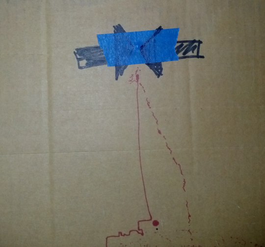
  4. WORKED:  The single point of cord attachment.  When I was using a crappy cardboard pen holder with cord attachment points very far apart, the entire pen holder would tip to one side or another when it got close to that side.  This caused a bubble-like distortion effect towards the edges of the drawing.  While this could be a cool effect to intentionally inflict on a drawing, it’s not what I was going for with that crappy cardboard design.  Having the two cords meet at exactly the same point worked out incredibly well.  Even when the robot was drawing the top left corner of Yoda’s lightsaber, the pen holder was always perfectly vertical.
  5. WORKED:  Shape of pen holder flat side.  The pen holder I’ve designed is roughly teardrop shaped, with a flat top.  My thought with giving it a “flat top” was that it wouldn’t potentially develop a central raised point (between the circular top edge of the pen holder and the device I was using for the pen lift) when I was doing a pen lift.  I figured that if I was using a “flat top” it was possible for the pen holder to be balanced on the edge of the flat top and the point of the servo arm – essentially turning my full contact pen holder into a three point contact pen holder with the servo arm as one of the points.
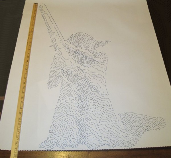
  6. DIDN’T WORK:  Motor skipping?  There is a large section in the middle of the drawing of Yoda, pictured above, that looks like it was shifted downwards slightly.  This could have been because I was fussing a little with the robot while it was working.  It could also have been because I was running the robot pretty fast (motor speed of 1600 when the normal is 600), because I had increased the acceleration (400 instead of the default 800), because I had the pots turned down too low (maybe, but the current settings have worked reasonably well for other drawings), because the pen holder was too heavy and causing too much strain on the motor (very unlikely since this holder is lighter than the cardboard abomination I was using) or some combination thereof.  My guess is that I probably need to increase the pots when I increase the speed.  It’s really unlikely that the pen holder itself was to blame for these missteps.2
  7. DIDN’T WORK:  The pen lift.  I haven’t drawn anything with a pen lift yet – but I did test the pen lift last night after Yoda was done.  I noticed a few minor problems with the pen lift – but nothing to indicate I was on a completely wrong track.
    1. The first problem is that I glued the two batteries slightly too close to the clearance area for the micro servo arm.  This is why the next version will include a holder for the AA batteries – to ensure they don’t get in the way.
    2. Second, even when fully extended the servo arm didn’t push out far enough to cause the pen tip to lift off the surface of the paper.  This could be solved by either making sure the pen tip is positioned slightly farther back, extending the servo arm, or creating a servo arm powered cam, similar to Dan Royer’s Makeangelo (check out the video at about 4:35 for a view of the cam in action).
    3. Third, my concern is that since the micro servo is mounted in such a way that the servo arm sweeps from right to left, it could cause a similar sweeping motion to be applied to the pen tip – assuming I work out the pen tip depth issues.  It’s possible that sweeping the arm upwards or downwards might minimize this effect.  I just have no idea whether this is a valid concern or not – the servo arm might move so quickly that it’s not a real concern.
    4. Also, while not an actual issue, the servo motor cable applies a bit of weight to the pen holder.  This will require me to reposition the cord attachment points – and may require me to add extra weights to the pen holder itself.

Once I change the pen position and maybe use a larger servo arm, I’ll try a vector drawing which requires pen lifts and re-evaluate this design.  Overall, this design has basically worked beautifully.  I’m looking forward to experimenting with some new variations on the design to see if I can eliminate the few remaining issues.

Default Series Title
  1. I’ll pretend I was doing this for a system stress-test, but really I was impatient to get a big giant Yoda drawing []
  2. Does that count as a pun? []

Fire the DrawBot!

Last night I connected my newly designed pen holder to my finished drawing robot and attempted a relatively “quick” drawing of Yoda.  I say “quick,” because it only took about two hours.  The one lone trade-off for having an cheap and easy to build robot capable of essentially unlimited drawing sizes is that it can take a long time.  I took several photographs of my robot while it was drawing and turned them into an animated GIF, featured at the end.

Finished and mounted robot, with old pen holder

Finished and mounted robot, with old pen holder

Above is the robot itself, mounted to the wall.  I’ve made two minor changes to this setup since that photo, detailed just below.  First, I’ve placed a large sheet of sacrificial cardboard under the paper so that any pen leaks will not mar the wall.  Second, since the “home point” (exactly 130mm down from the exact midpoint between the two spots where the cord leaves the project box) is hidden by the paper when I pull it down, I needed a way to be able to center the robot without having to re-measure the home point each time.  My solution was to take a small piece of leftover plastic about the size of a pinhead and tape it to the home point on the cardboard.  Now, I can feel the home point through the sheet of paper and center the pen holder accordingly.

Home point for centering the pen holder

Home point for centering the pen holder

It’s a little difficult to make out in the photo above, but you can see the two big arrows pointing to the home point and a slight bulge in the tape caused by the small plastic speck.

Brand new pen holder, assembled

Brand new pen holder, assembled

This picture shows the pen holder fully assembled.  I operated it the first time without the benefit of a servo motor cable.  I wanted to see if the pen holder would work well.  Once the drawing was about 2/3 done and I was pretty happy with the pen holder’s operation, I soldered up a cable to connect the servo lift port to the servo motor.

Drawing robot in action

Drawing robot in action

The above animated GIF is comprised of eight separate photos from my digital camera on a tripod, combined in GIMP.  I’ve never to make an animated GIF from a series of photos, but it very quick and painless.  Since video takes up a lot of space and battery power, I figured a series of photos would be the easiest way to create a “time lapse” of the robot’s operation.  You don’t get the low drone and hum of the motors, but you can see how it operates.  Now that I’ve done one, I’m looking forward to making more of these.

Yoda, standing tall

Yoda, standing tall

And here is Yoda!  As you can see from the ruler next to him, he’s about 35 inches tall from the tip of the lightsaber to his feet.  There’s a “band” of the drawing that appears to be shifted downwards slightly, causing a little overlap at the bottom of that region and a slight gap above.  This is probably due to me fiddling with the robot, but it could also be due to the motors slipping or skipping slightly during operation.  If it was due to me fiddling with the robot, then the fix is simple – I just need to be more patient.  If it was due to the motors skipping steps, then turning up the pots just a little would probably fix that.  Given that this is the very first drawing from my very first draft of a new pen holder, I’m really happy with the result.

Arduino Powered Drawing Robot Poll

Arduino Drawing Robots - what would you like to know?

View Results

Loading ... Loading ...

Thanks for checking out my DrawBot Adventure Series.  For the last 13 months I’ve been blogging all about my adventures in learning basic Arduino skills, basic robot building skills, applying my limited soldering skills, talking about my numerous fails and occasional triumphs, in building a drawing robot.  So far I’ve racked up 66 blog posts about drawing robots (which is about 5/month) and shared all of my designs and improvements1 freely on Thingiverse.

But, this is really just me typing up stuff as it occurs to me.  I would rather write a bunch of stuff you want to read.  So, I would really appreciate it if you could take a minute and let me know – what do you want to know about awesome Arduino powered drawing robots?  Please take a quick moment and let me know.  If you don’t see an option above that suits you, please leave a comment.

After you’re done, you may want to check out some of the posts in the series in the links below!  I’d suggest starting here.

Default Series Title
  1. And one epic fail []

DrawBot – A Preview

Drawing Robot - Preview

Drawing Robot – Preview

Unfortunately, it will be a few more days yet before I can completely finish the drawing robot.  I still need to order some rainbow ribbon cable and connects, wire up the motors, and then actually draw something with the brand spanking new PolargraphSD brain.  For now, please just ignore the mess of wires and the superfluous Arduino + Adafruit motor shield in the middle.  The blue tape on the paper roll is just there to keep it from unfurling.

As you can see, the project box looks so much better without all the clutter inside.  Once I’ve gotten everything all set up and tested, I plan to add some internal wire guides to keep the wires in check.  That should help the whole project look a lot more clean and pleasing.

I’m fighting my perfectionist1 to keep printing and reprinting parts.  I had the idea to have dualstrusion printed spools.  I know from experience that rotating single color spools don’t look all that much different that from non-rotating single color spools.  A spool with a dualstrusion pattern embedded in it would provide some kind of interesting visual confirmation that the robot was operational.  Then again, I do like having a very monochrome project – unpainted, unvarnished wood, black ABS plastic, and black oxide bolts.2

You can see above that I’ve already drilled a rough hole into the right side of the box to route the power cable through.  There’s just enough clearance in that hole to allow a USB-B cable to go through as well.

I’ve tried to use a very modular system that allows me to loosen and tighten parts in place with a single bolt.  While making minor adjustments here and there, this system has been amazingly useful.

I’ve taken several more pictures of the various plastic parts and how they fit together.  I’ll post about these shortly.3

Default Series Title
  1. Yes, I do have some perfectionist tendencies… []
  2. Except the shiny M3x8 bolts used to mount the motors.  I wish they didn’t bother me as much as they do. []
  3. Well, to be perfectly accurate, I’ll post about these plastic parts soon.  If you’re a regular reader of the blog, you’ll note that few of the posts could be legitimately described “shortly.” []

DrawBot – A Tour!

Dual use project box

Dual use project box

Above is a picture of my drawing robot, still a work in progress.  The great thing about this particular project box is that it also doubles as a work area.  It’s a good place to cut and strip wires, solder, assemble parts, and it’s totally portable.  The box is 3′ long, 8″ high, 2″ inches deep.

  • A. Printed Bolt Covers.  An M3 nut goes into the recess and the end of the bolt is covered by the printed part.  One of these goes over every one of the protruding bolts in the project box.
  • B. Printed Paper Roll Mounts, on a Slide.  These are actually three separate printed parts.  Since the paper roll came without a cardboard tube, I put a wooden dowel down the center, with printed plastic caps on either side to hold the paper in place.  There are two printed holders which the wooden dowel slot into.  Each of the printed dowel holders slide left and right on a track and have a bolt that can be tightened to keep it from moving.
  • C. Paper Roll.  After looking in a few craft stores I finally found a big long roll of paper at Staples of all places.  I think it was marketed as paper you would use to cover a table.  It’s thin paper, but there’s a lot of it and it was really cheap.  With no internal cardboard tube, I had to design endcaps to keep it from wobbling all around.
  • D. Maker Faire Application.  I’m hoping to display this robot at Maker Faire Bay Area 2013.  Since the call for Makers hasn’t gone out yet I just downloaded the Maker Faire New York 2012 application and filled it out.  Now when the call for Makers comes, I’ll be ready.
  • E. Wire Cutters and Pliers.  These are just necessary tools.  When I need something to hold tiny parts I wrap a rubber band around the pliers and they’re a tiny vise.
  • F. Printed Spools.  Two printed plastic parts plus three nuts and bolts.  Definitely overengineered, but they don’t have the weaknesses of a single print spool.
  • G. Motor Bolted to Motor Mount, on a Slide.  The motors are bolted to a plastic mount with a groove.  The motor mount is then slotted onto the slide which is itself bolted to the actual project box.
  • H. PolargraphSD in a Printed Case. I designed and printed the case.  The way it is mounted to the project box, it is slightly offset from the box, which gives the circuit boards extra ventilation.
  • I. Stick Lighter.  I used this stick lighter to heat the heat shrink.
  • J. Heat Shrink.  Lots of heat shrink in varying colors and diameters.
  • K. Printed Gondola.  This is John Abella’s gondola.
  • L. Soldering Iron.  A cheap soldering iron.
  • M. Adafruit Motor Shield on an Arduino Uno, in a Printed Holder.  Well, that about says it all.  I would point out that the printed holder is pretty terrible – it’s just a little too small.  The only reason I put the Arduino and shield in the box was so that I could hook up the motors and make sure everything was still in operating condition.
  • N. Big Container of Zip Ties.  Zip ties are useful.
  • O. Solder.  For soldering.
  • P. Monofilament Guide.  You can’t see it, but there’s a little plastic tube that fits into a hole drilled through the wood project box.  It’s much smoother than wood and works great.

I’ve taken a lot of detailed pictures of the various parts and how they go together, so that comes next.

Default Series Title

This project is not going to overengineer itself

Seriously, why would anyone with hands buy this?

Seriously, why would anyone with hands buy this?

This weekend I worked on my DrawBot.  ((Photo courtesy of Relly Annett-Baker))  I stripped my current DrawBot for parts so that I may build it back together with a PolagraphSD brain/heart.  ((Bart?  Hain?))  Given that there aren’t a ton of parts involved, the process went quickly.  I disconnected the two steppers, pulled all the screws1 and all the nuts and bolts2 from the project.  Right now all that is left of my once mighty3 drawing robot is an Arduino and shield duct taped to a chunk of plywood.

To assemble the new robot into the desired configuration ((Sketch D for those of you playing along at home)) I needed to design:

  • A new PolargraphSD case
    • This new case is about 2/3 the volume of Sandy’s design and has vents along the sides and top to help with heat dissipation.  It can also be assembled without any tools or hardware – with the LCD actually keeping the entire thing together.  At this point I now have three perfectly serviceable cases.  My goal, once the entire robot is put together, is that it look and feel like a finished and polished project – a DONE project.  But, really, I’d like to have it semi-permanently installed somewhere in my house as a drawing appliance.  My prior ‘bot while cool with tons of nifty little hacker cred to it was little more than a chunk of plywood with bits hanging off.  I’d draw something with it, put the board away, then bring it out later.
    • My ideas for building out the robot have changed slightly since designing this case, so I might need to adjust the code and print another one.  The issue now is that the case is designed to be mounted by being bolted into the base of the project box.  However, if I do that a nut or bolt will have to stick through the back of the project which will prevent the paper roll from being able to travel behind the project box.  I figure I could print a new case and bolt it to the side of the project box – but that might interfere with the location of the motors/motor mounts.  I might be able to just ziptie the case to the top of the project box – which might not be good as the bot is expect to shake a little in operation and I don’t want the board shaken unnecessarily.  Frankly, at this point, I think I’ll get everything else situated completely within the project box and come back to figuring out how to mount the case.
    • Although, an idea which just occurred to me is that I could glue some plastic mounts, with captive nuts, into the inside of the project box and bolt the case into that.  Again, this would best be done once all the other issues are resolved.
  • New monofilament spools
    • I had to completely destroy my existing spools to get them off the motor shafts.  For some god-awful reason I printed the two spools at 100% infill creating the sturdiest monofilament spools in existence.  I cannot imagine what possessed me to do this.  They were heavy and impossible to remove cleanly from the motor shafts.  I didn’t get the tolerances right with the prior spools, so I had to force them onto the shafts – but then they were stuck.  I had to use a big pair of wirecutters to chop chunks of plastic off until I could pull the last bits free from the motor.  When I finish designing and printing a new set of spools, I’m going to make sure the tolerances are right before I assemble.  I want the spools to fit snugly becuase I don’t want the motor to slip when it reverses directions – as it will do frequently across a large drawing.
    • I’m still kicking around ideas on how to improve the spools.  My first spools were way too complex and the friction fit wasn’t enough to keep them together.  My second set was too tight and too short.  While I wouldn’t mind a friction fit spool, I need a spool that can’t come apart during operation4 , can be tightened on the motor shaft, and can be removed easily if necessary.  Additionally, I’d like the final spool to be taller – so that there is more of the spool center and less of the flared end of the spool for the filament to wind onto.  The flared end was flared so that the spool could be printed as a single piece.  While this was nice for simplicity’s sake, I found that sometimes the filament line would “ride up” the flared end – which introduces unnecessary error into the process.
    • Looking at the AS220 Labs website page for their drawing robot kit through Archive.org, you will notice that they use a tall spool with a low-friction monofilament line guide.  The benefit of the tall spool is that it can keep a more consistent diameter for more of the filament versus a narrow spool that will accumulate layers of filament more quickly.  The benefit of the line guide is that it forces the robot to maintain the proper distance between the two motors even when the spools are mounted horizontally.  I also happen to like the horizontal spool mount system since it means the motors won’t stick out from the wall quite so much.5
  • A new gondola
  • A way to mount a roll of paper to my project box
    • Besides tearing my drawing robot apart, this is the one thing I did manage to design, print, and put together over the weekend.  Since the paper roll I’m using did not come with a center of cardboard or wood or on any kind of spindle, it is not an immediately mountable thing.  My roll of paper is just that – a really long roll of paper.
    • What I wanted was a modular way to mount a roll of paper to the top of my project box so that it could be adjusted to fit different diameters and widths of paper rolls.  My solution was to print two “caps” to go at either end of the paper roll, with a hole through them to run a long wooden dowel.  The nifty part is where I then bolted two printed plastic tracks to the top of my project box, onto which I can slide a plastic arm which the wooden dowel fits into.  Once the two plastic arms are in place, they can be tightened down onto the plastic track.  The result is a rock solid paper roll mount that lets the paper roll freely turn.  I was so happy with the way this turned out I almost couldn’t see straight.  Yes, it is just a mount for a roll of paper – but it is the most solid and polished way one might hope to mount a core-less roll of paper on top of a wooden box.
  • A new way to mount the stepper motors to the project box
    • Given the amount of time I’ve spent just mounting a roll of paper and obsessing about spools, is it any wonder I haven’t finished thinking about how to mount the steppers?  With the first incarnation of my drawing robot I had designed and printed no less than three completely different motor mounts.
    • I would like the final version of the motor mounts to be easily adjustable, probably using a similar track/mount system that I used to mount the paper roll.  While this kind of solution takes more time to design, the result is a robot that can be quickly and easily improved and adjusted.  As suggested above in the spool section, I am leaning towards mounting the motors so that the shafts are horizontal on the plate of the wall.  This will let the motors keep a slim profile in the project box and allow the use of a tall spool which will enable more even and uniform reeling and unreeling of monofilament.
    • I’m tempted to incorporate a monofilament line guide directly into the motor mount.  In the interests of modularity, it makes sense to keep these things separate, but it might just make sense to do this given the limited space I’ve got within the depth of this shallow project box.6

I’m undecided whether I want to put a cover on the front of my project box.  On the one hand leaving the front of the project box open allows the viewer to peer into the robot and marvel at its simplicity.  On the other hand, without viewing the internals all you would see is a box mounted on the wall, a paper roll on top of that, a power cord coming out of the side, and a drawing pen moving by two almost imperceptible monofilament lines.  Perhaps I should explore this idea in another long winded post?

Default Series Title
  1. Four total []
  2. 12 nuts and four bolts []
  3. Mighty UGLY, that is! []
  4. When one of the friction fit spools failed mid-drawing, it was like watching my robot puke monofilament line.  Frankly, a monofilament puking robot is pretty awesome – just not when it is made from a drawing robot []
  5. If you were betting on me not being able to type an ENTIRE Page of text just on the considerations of the spools in my robot, you would have lost. []
  6. For reference, the box I’m using is less than 2 inches deep. []