Fire the DrawBot!

Last night I connected my newly designed pen holder to my finished drawing robot and attempted a relatively “quick” drawing of Yoda.  I say “quick,” because it only took about two hours.  The one lone trade-off for having an cheap and easy to build robot capable of essentially unlimited drawing sizes is that it can take a long time.  I took several photographs of my robot while it was drawing and turned them into an animated GIF, featured at the end.

Finished and mounted robot, with old pen holder

Finished and mounted robot, with old pen holder

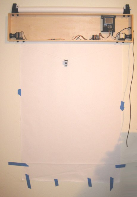
Above is the robot itself, mounted to the wall.  I’ve made two minor changes to this setup since that photo, detailed just below.  First, I’ve placed a large sheet of sacrificial cardboard under the paper so that any pen leaks will not mar the wall.  Second, since the “home point” (exactly 130mm down from the exact midpoint between the two spots where the cord leaves the project box) is hidden by the paper when I pull it down, I needed a way to be able to center the robot without having to re-measure the home point each time.  My solution was to take a small piece of leftover plastic about the size of a pinhead and tape it to the home point on the cardboard.  Now, I can feel the home point through the sheet of paper and center the pen holder accordingly.

Home point for centering the pen holder

Home point for centering the pen holder

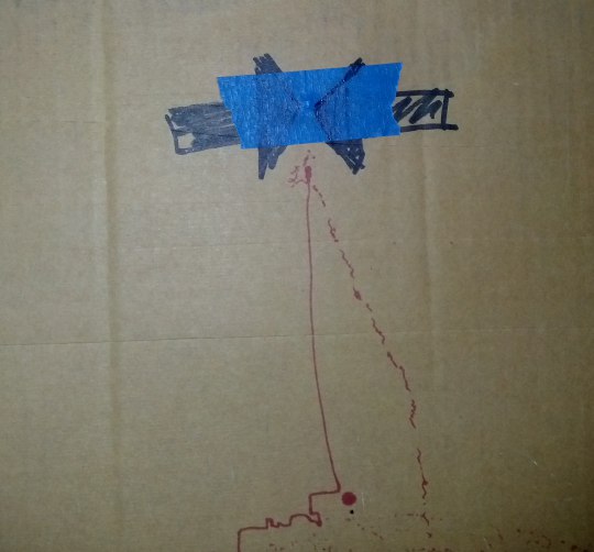
It’s a little difficult to make out in the photo above, but you can see the two big arrows pointing to the home point and a slight bulge in the tape caused by the small plastic speck.

Brand new pen holder, assembled

Brand new pen holder, assembled

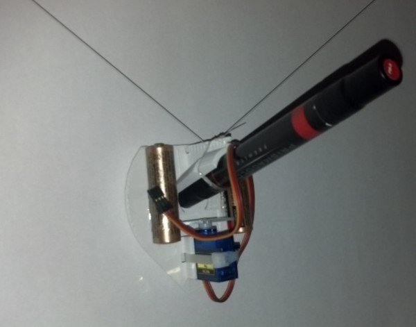
This picture shows the pen holder fully assembled.  I operated it the first time without the benefit of a servo motor cable.  I wanted to see if the pen holder would work well.  Once the drawing was about 2/3 done and I was pretty happy with the pen holder’s operation, I soldered up a cable to connect the servo lift port to the servo motor.

Drawing robot in action

Drawing robot in action

The above animated GIF is comprised of eight separate photos from my digital camera on a tripod, combined in GIMP.  I’ve never to make an animated GIF from a series of photos, but it very quick and painless.  Since video takes up a lot of space and battery power, I figured a series of photos would be the easiest way to create a “time lapse” of the robot’s operation.  You don’t get the low drone and hum of the motors, but you can see how it operates.  Now that I’ve done one, I’m looking forward to making more of these.

Yoda, standing tall

Yoda, standing tall

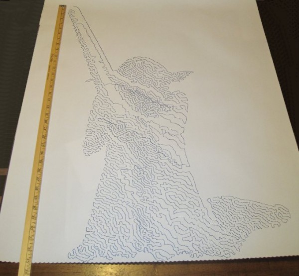
And here is Yoda!  As you can see from the ruler next to him, he’s about 35 inches tall from the tip of the lightsaber to his feet.  There’s a “band” of the drawing that appears to be shifted downwards slightly, causing a little overlap at the bottom of that region and a slight gap above.  This is probably due to me fiddling with the robot, but it could also be due to the motors slipping or skipping slightly during operation.  If it was due to me fiddling with the robot, then the fix is simple – I just need to be more patient.  If it was due to the motors skipping steps, then turning up the pots just a little would probably fix that.  Given that this is the very first drawing from my very first draft of a new pen holder, I’m really happy with the result.

Drawing Robot Pen Holders, Calligraphy Pens, and Thought Experiments

Just hanging out

Just hanging out

In discussing Sandy Noble’s Polargraph pen holder I mentioned how his design is optimized so that the point where the two cords meet is always the same as where the pen tip meets the paper.1 In the comments, he explained his rational, “So the pen tip is always at the tip of the hanging triangle, and there’s no distortion that way.”  My response was that “…if the pen holder has a single ‘hanging triangle’ point in it with the pen tip a constant distance from that ‘hanging triangle point,’ the drawings should appear identical to those created at the ‘hanging triangle point’ – just offset by the constant distance.”

This morning Sandy updated his site with a post explaining, using several diagrams, the basis for his prior theory and how he came to agree with my point. (Not that he’s changing his pen holders…  ;)  )

Without as much fancy-schmancy maths and geometry, I figured I would explain the thought experiment I used to conclude that a pen tip that is always a constant distance and position from the “hanging triangle point” will always produce an accurate distortion-free drawing.  To help illustrate these thought experiments, I’ve enlisted the help of Yoda.  “Hi Yoda!”

Fig 1:  Yoda, being drawn by a drawing robot

Fig 1: Yoda, being drawn by a drawing robot

In the picture above, Yoda is being drawn by a drawing robot.

Fig 2: Yoda drawing, annotated

Fig 2: Yoda drawing, annotated

Above, I’ve labeled the important parts of the drawing.  On the top left “Motor A,” on the top right “Motor B,” which are attached by cords to the pen holder indicated by the dark blue line.  Here, I’ve shown Yoda as he would be drawn by a drawing robot, where the robot then draws two more points.

Let’s say, because we’re feeling whimsical today, we want to add a second pen to our pen holder.  We’ll use a red pen and affix it below the blue pen in such a way that the red pen will always be directly below the blue pen by the same distance.

Fig 3:  Another pen

Fig 3: Another pen

For the moment let’s pretend the red pen is capped so it won’t leave a mark.  Now we’ll try to predict the position of the red pen at different points along the original drawing.

Fig 4: Where's the red pen?

Fig 4: Where’s the red pen?

It turns out this task is pretty easy.  The red pen, at any given point during the Yoda drawing, will always be directly below the blue pen by the same exact distance between the two pens.  Okay, now let’s draw Yoda again – this time with the red cap off.

Fig 5: Double vision

Fig 5: Double vision

We get two Yodas!  How awesome is that!  The reason I mentioned calligraphy pens in the title of this post is because it shows another way to think about this process.  When we write with a calligraphy pen we don’t have one end of the pen wildly distorted – in theory the two points on the calligraphy pen are always a constant distance from one another and moving together (as long as we don’t rotate the pen when we write).  You could imagine instead of a blue and red pen above, we’ve put a single calligraphy pen that’s as wide as the black line representing the distance between the two pens above.  The resulting drawing would look like a Yoda – that had been smudged downwards by the same distance.

Let’s now draw Yoda again, but capping the blue pen and still tracking where the blue pen would be.

Fig 6: Not using the blue pen

Fig 6: Not using the blue pen

We should end up with a result very similar to Fig 4.  It’s the same Yoda, only red and shifted down from the original blue Yoda by the distance between the two pens.

Let’s draw Yoda again – this time we’ve still got a pen holder which has the cord from Motor A meet Motor B at exactly one point.  As Sandy points out, this is really easy to do when you aren’t worrying about making that exact point be the same precise point as the pen tip.  Directly below point where the two cords meet on the pen holder, we’ll put the red pen.  From a functional standpoint, this setup is identical scenario to Fig 6.

Fig 7: Drawing just one red Yoda

Fig 7: Drawing just one red Yoda

Now we have a red Yoda, shifted down on the paper by the distance between the point where the two cords meet and where the red pen touches the paper.  It’s important to note that there’s no special magic to having the red pen directly below the point where the cords converge.  This pen tip just needs to be a constant distance and position from the cord convergence point at any given time.  While it might be more difficult to build a pen holder that holds the pen far off to one side, there’s no reason this wouldn’t work.

Fig 8: Yoda, now in green

Fig 8: Yoda, now in green

The lessons I take from this thought experiment are:

  1. As long as the pen is a constant distance and constant position from the point where the two cords meet, your drawing will not appear distorted – just shifted by the same constant distance and position.
  2. When calibrating the robot, the operator would need to calibrate the pen holder position by the cords convergence point – not the pen point.  This means that the preview in your software won’t match exactly the position of your drawing on the paper.  
  3. While not part of the thought experiment per se, I think we can all agree that the more weight that is not centered on the cord convergence point, the more likely the pen holder is to sway.
  4. I’m willing to defer to Sandy’s experience that pen holders that do not have the cord convergence point the same as the pen tip are, “Easier to design, easier to build, and cheaper, far, far cheaper.”

Thanks Yoda!

P.S.  Just in case you’re wondering – the reason that SVG of Yoda above is so large is because it includes the full TSP version of Yoda I’m getting ready to draw.  :)

Default Series Title
  1. Photo courtesy of Kristina Alexanderson []