I generally share my 3D designs freely on Thingiverse. Some designs I don’t care much about, I share them in case someone else might fight them interesting or useful. Some I don’t have much of a right to – a very slight variation / derivative of someone else’s work or a derivative of a work that walks the fine line that is “fair use” such as my OpenSCAD Voltron. Some of my designs are things which I think I might be able to turn into something I could sell or be the start of a little business.
And some of my designs I want to share and am particularly proud of – such as my sushi set, pirate ship, and the printed parts for my PlotterBot. For these very few designs, I choose a “non-commercial” license. I’m so proud of these designs that I want to share them, and yet I feel that my creativity and hard work merits reward – especially if someone makes a profit off of them.
A single cord convergence point. “Have the two strings meet at a single point, or as close as possible. The moment they separate the math gets really ugly.”
Deal with friction. “Friction causes the pen to drag and lean. If I tell the robot to draw a square corner and it comes out rounded then I know my pen is dragging because it never reached the corner. The pen has to stay at a right angle to the drawing surface. So far I’ve found that having at least three points of contact is enough to eliminate the problem. That’s why I tape my business card to an eye bolt on the bottom of the ring – the bottom edge of the card forms a large contact area with very little friction.”
Be well balanced. “If the pen is balanced wrong it may point up or down. If it points up then it might go dry. If it points down then it might have extra friction when moving downwards, causing the pen to skip and create a dotted line.”
Have an easy way to switch pens. “Not only should it be easy to replace a pen but every pen should “lock” into the pen holder at the same distance and angle from the drawing surface. In order to simplify this problem I only use one kind of pen that comes in many colors.”
Works on a slanted surface. “Works on both vertical and slanted surfaces up to a maximum of 10 degrees.”
My own prior post on ideal characteristics in a pen holder took into account Dan’s number 1, 3, 4 and considered 5. What I failed to consider was how friction can cause the pen to skip or stutter when the pen is mounted at an angle and the pen travels upwards.
Although I started diving into this consideration, but I’m putting all that over-pontification into its own post. This post is really about (a) Dan considered a very important factor in pen holder construction which I neglected and (b) how awesome open source is. My own pen holder would be a terribly complicated mess doomed to multiple revisions had I not had the benefit of being able to review a veritable legion of pen holders used by many many other people in their many many different kinds of vertical drawing robots.
WORKED: The fit. I’m really happy with how the pen holder went together. It’s always very satisfying to print a part you just designed and have it “just fit.” With the zip tie holding the micro servo in place, neither the micro servo tab nor the zip tie protrude beyond the flat surface of the pen holder. The groves for the rubber band to hold the pen in place work very well. The pen doesn’t move side-to-side, get pushed back into the holder, and it is very easy to reposition the pen or change pens entirely. While it’s not as elegant as, say, a metal spring, it works very well and doesn’t require a bunch of moving parts.
WORKED: The amount and placement weight. I hot glued a AA battery to either side of the pen holder, as close to the center as I could manage around the hole for the pen. This weight seemed to work perfectly. There was enough weight that the cords hung in straight lines, but not so much that it seemed to cause a strain on the motors. The placement of the weights seemed to work well as there was no noticeable pendulum swinging of the pen holder, despite me running the robot at about three times it’s usual top motor speed and about twice it’s normal acceleration.1
WORKED: The multiple points of cord attachment. Having a row of holes for connecting the cords at different points along the top central edge of the pen holder worked out great. To test the balance all I did was stick a small paperclip through a hole. If the holder balanced with the flat edge upright and vertical, that’s the point I needed. It was easy to find the balance point and easy to connect the cords.
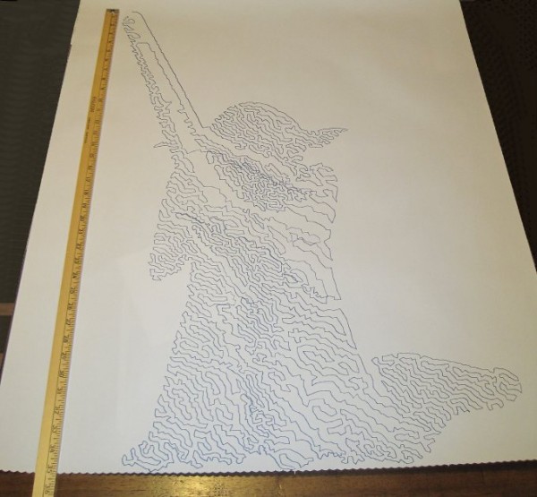
WORKED: The single point of cord attachment. When I was using a crappy cardboard pen holder with cord attachment points very far apart, the entire pen holder would tip to one side or another when it got close to that side. This caused a bubble-like distortion effect towards the edges of the drawing. While this could be a cool effect to intentionally inflict on a drawing, it’s not what I was going for with that crappy cardboard design. Having the two cords meet at exactly the same point worked out incredibly well. Even when the robot was drawing the top left corner of Yoda’s lightsaber, the pen holder was always perfectly vertical.
WORKED: Shape of pen holder flat side. The pen holder I’ve designed is roughly teardrop shaped, with a flat top. My thought with giving it a “flat top” was that it wouldn’t potentially develop a central raised point (between the circular top edge of the pen holder and the device I was using for the pen lift) when I was doing a pen lift. I figured that if I was using a “flat top” it was possible for the pen holder to be balanced on the edge of the flat top and the point of the servo arm – essentially turning my full contact pen holder into a three point contact pen holder with the servo arm as one of the points.
DIDN’T WORK: Motor skipping? There is a large section in the middle of the drawing of Yoda, pictured above, that looks like it was shifted downwards slightly. This could have been because I was fussing a little with the robot while it was working. It could also have been because I was running the robot pretty fast (motor speed of 1600 when the normal is 600), because I had increased the acceleration (400 instead of the default 800), because I had the pots turned down too low (maybe, but the current settings have worked reasonably well for other drawings), because the pen holder was too heavy and causing too much strain on the motor (very unlikely since this holder is lighter than the cardboard abomination I was using) or some combination thereof. My guess is that I probably need to increase the pots when I increase the speed. It’s really unlikely that the pen holder itself was to blame for these missteps.2
DIDN’T WORK: The pen lift. I haven’t drawn anything with a pen lift yet – but I did test the pen lift last night after Yoda was done. I noticed a few minor problems with the pen lift – but nothing to indicate I was on a completely wrong track.
The first problem is that I glued the two batteries slightly too close to the clearance area for the micro servo arm. This is why the next version will include a holder for the AA batteries – to ensure they don’t get in the way.
Second, even when fully extended the servo arm didn’t push out far enough to cause the pen tip to lift off the surface of the paper. This could be solved by either making sure the pen tip is positioned slightly farther back, extending the servo arm, or creating a servo arm powered cam, similar to Dan Royer’s Makeangelo (check out the video at about 4:35 for a view of the cam in action).
Third, my concern is that since the micro servo is mounted in such a way that the servo arm sweeps from right to left, it could cause a similar sweeping motion to be applied to the pen tip – assuming I work out the pen tip depth issues. It’s possible that sweeping the arm upwards or downwards might minimize this effect. I just have no idea whether this is a valid concern or not – the servo arm might move so quickly that it’s not a real concern.
Also, while not an actual issue, the servo motor cable applies a bit of weight to the pen holder. This will require me to reposition the cord attachment points – and may require me to add extra weights to the pen holder itself.
Once I change the pen position and maybe use a larger servo arm, I’ll try a vector drawing which requires pen lifts and re-evaluate this design. Overall, this design has basically worked beautifully. I’m looking forward to experimenting with some new variations on the design to see if I can eliminate the few remaining issues.
Default Series Title
I’ll pretend I was doing this for a system stress-test, but really I was impatient to get a big giant Yoda drawing [↩]
This weekend I worked on my DrawBot. ((Photo courtesy of Relly Annett-Baker)) I stripped my current DrawBot for parts so that I may build it back together with a PolagraphSD brain/heart. ((Bart? Hain?)) Given that there aren’t a ton of parts involved, the process went quickly. I disconnected the two steppers, pulled all the screws1 and all the nuts and bolts2 from the project. Right now all that is left of my once mighty3 drawing robot is an Arduino and shield duct taped to a chunk of plywood.
To assemble the new robot into the desired configuration ((Sketch D for those of you playing along at home)) I needed to design:
This new case is about 2/3 the volume of Sandy’s design and has vents along the sides and top to help with heat dissipation. It can also be assembled without any tools or hardware – with the LCD actually keeping the entire thing together. At this point I now have three perfectly serviceable cases. My goal, once the entire robot is put together, is that it look and feel like a finished and polished project – a DONE project. But, really, I’d like to have it semi-permanently installed somewhere in my house as a drawing appliance. My prior ‘bot while cool with tons of nifty little hacker cred to it was little more than a chunk of plywood with bits hanging off. I’d draw something with it, put the board away, then bring it out later.
My ideas for building out the robot have changed slightly since designing this case, so I might need to adjust the code and print another one. The issue now is that the case is designed to be mounted by being bolted into the base of the project box. However, if I do that a nut or bolt will have to stick through the back of the project which will prevent the paper roll from being able to travel behind the project box. I figure I could print a new case and bolt it to the side of the project box – but that might interfere with the location of the motors/motor mounts. I might be able to just ziptie the case to the top of the project box – which might not be good as the bot is expect to shake a little in operation and I don’t want the board shaken unnecessarily. Frankly, at this point, I think I’ll get everything else situated completely within the project box and come back to figuring out how to mount the case.
Although, an idea which just occurred to me is that I could glue some plastic mounts, with captive nuts, into the inside of the project box and bolt the case into that. Again, this would best be done once all the other issues are resolved.
New monofilament spools
I had to completely destroy my existing spools to get them off the motor shafts. For some god-awful reason I printed the two spools at 100% infill creating the sturdiest monofilament spools in existence. I cannot imagine what possessed me to do this. They were heavy and impossible to remove cleanly from the motor shafts. I didn’t get the tolerances right with the prior spools, so I had to force them onto the shafts – but then they were stuck. I had to use a big pair of wirecutters to chop chunks of plastic off until I could pull the last bits free from the motor. When I finish designing and printing a new set of spools, I’m going to make sure the tolerances are right before I assemble. I want the spools to fit snugly becuase I don’t want the motor to slip when it reverses directions – as it will do frequently across a large drawing.
I’m still kicking around ideas on how to improve the spools. My first spools were way too complex and the friction fit wasn’t enough to keep them together. My second set was too tight and too short. While I wouldn’t mind a friction fit spool, I need a spool that can’t come apart during operation4 , can be tightened on the motor shaft, and can be removed easily if necessary. Additionally, I’d like the final spool to be taller – so that there is more of the spool center and less of the flared end of the spool for the filament to wind onto. The flared end was flared so that the spool could be printed as a single piece. While this was nice for simplicity’s sake, I found that sometimes the filament line would “ride up” the flared end – which introduces unnecessary error into the process.
Looking at the AS220 Labs website page for their drawing robot kit through Archive.org, you will notice that they use a tall spool with a low-friction monofilament line guide. The benefit of the tall spool is that it can keep a more consistent diameter for more of the filament versus a narrow spool that will accumulate layers of filament more quickly. The benefit of the line guide is that it forces the robot to maintain the proper distance between the two motors even when the spools are mounted horizontally. I also happen to like the horizontal spool mount system since it means the motors won’t stick out from the wall quite so much.5
Besides tearing my drawing robot apart, this is the one thing I did manage to design, print, and put together over the weekend. Since the paper roll I’m using did not come with a center of cardboard or wood or on any kind of spindle, it is not an immediately mountable thing. My roll of paper is just that – a really long roll of paper.
What I wanted was a modular way to mount a roll of paper to the top of my project box so that it could be adjusted to fit different diameters and widths of paper rolls. My solution was to print two “caps” to go at either end of the paper roll, with a hole through them to run a long wooden dowel. The nifty part is where I then bolted two printed plastic tracks to the top of my project box, onto which I can slide a plastic arm which the wooden dowel fits into. Once the two plastic arms are in place, they can be tightened down onto the plastic track. The result is a rock solid paper roll mount that lets the paper roll freely turn. I was so happy with the way this turned out I almost couldn’t see straight. Yes, it is just a mount for a roll of paper – but it is the most solid and polished way one might hope to mount a core-less roll of paper on top of a wooden box.
A new way to mount the stepper motors to the project box
Given the amount of time I’ve spent just mounting a roll of paper and obsessing about spools, is it any wonder I haven’t finished thinking about how to mount the steppers? With the first incarnation of my drawing robot I had designed and printed no less than three completely different motor mounts.
I would like the final version of the motor mounts to be easily adjustable, probably using a similar track/mount system that I used to mount the paper roll. While this kind of solution takes more time to design, the result is a robot that can be quickly and easily improved and adjusted. As suggested above in the spool section, I am leaning towards mounting the motors so that the shafts are horizontal on the plate of the wall. This will let the motors keep a slim profile in the project box and allow the use of a tall spool which will enable more even and uniform reeling and unreeling of monofilament.
I’m tempted to incorporate a monofilament line guide directly into the motor mount. In the interests of modularity, it makes sense to keep these things separate, but it might just make sense to do this given the limited space I’ve got within the depth of this shallow project box.6
I’m undecided whether I want to put a cover on the front of my project box. On the one hand leaving the front of the project box open allows the viewer to peer into the robot and marvel at its simplicity. On the other hand, without viewing the internals all you would see is a box mounted on the wall, a paper roll on top of that, a power cord coming out of the side, and a drawing pen moving by two almost imperceptible monofilament lines. Perhaps I should explore this idea in another long winded post?
When one of the friction fit spools failed mid-drawing, it was like watching my robot puke monofilament line. Frankly, a monofilament puking robot is pretty awesome – just not when it is made from a drawing robot [↩]
If you were betting on me not being able to type an ENTIRE Page of text just on the considerations of the spools in my robot, you would have lost. [↩]
For reference, the box I’m using is less than 2 inches deep. [↩]
One of things I really like about OpenSCAD is how anything I make in it is guaranteed to be manifold. It’s a solid modeler and by manipulating, adding, and subtracting solids – I should always end up with another solid. I exported two of the parts necessary for a Pez Powered Disc Shooter only to discover that OpenSCAD refused to compile one of the parts – because that part had some polygons with an incorrect winding order. Mind, I had no problems exporting the part in the first place – but importing it back? Nope.