Seriously, why would anyone with hands buy this?
This weekend I worked on my DrawBot. ((Photo courtesy of Relly Annett-Baker)) I stripped my current DrawBot for parts so that I may build it back together with a PolagraphSD brain/heart. ((Bart? Hain?)) Given that there aren’t a ton of parts involved, the process went quickly. I disconnected the two steppers, pulled all the screws and all the nuts and bolts from the project. Right now all that is left of my once mighty drawing robot is an Arduino and shield duct taped to a chunk of plywood.
To assemble the new robot into the desired configuration ((Sketch D for those of you playing along at home)) I needed to design:
- A new PolargraphSD case
- This new case is about 2/3 the volume of Sandy’s design and has vents along the sides and top to help with heat dissipation. It can also be assembled without any tools or hardware – with the LCD actually keeping the entire thing together. At this point I now have three perfectly serviceable cases. My goal, once the entire robot is put together, is that it look and feel like a finished and polished project – a DONE project. But, really, I’d like to have it semi-permanently installed somewhere in my house as a drawing appliance. My prior ‘bot while cool with tons of nifty little hacker cred to it was little more than a chunk of plywood with bits hanging off. I’d draw something with it, put the board away, then bring it out later.
- My ideas for building out the robot have changed slightly since designing this case, so I might need to adjust the code and print another one. The issue now is that the case is designed to be mounted by being bolted into the base of the project box. However, if I do that a nut or bolt will have to stick through the back of the project which will prevent the paper roll from being able to travel behind the project box. I figure I could print a new case and bolt it to the side of the project box – but that might interfere with the location of the motors/motor mounts. I might be able to just ziptie the case to the top of the project box – which might not be good as the bot is expect to shake a little in operation and I don’t want the board shaken unnecessarily. Frankly, at this point, I think I’ll get everything else situated completely within the project box and come back to figuring out how to mount the case.
- Although, an idea which just occurred to me is that I could glue some plastic mounts, with captive nuts, into the inside of the project box and bolt the case into that. Again, this would best be done once all the other issues are resolved.
- New monofilament spools
- I had to completely destroy my existing spools to get them off the motor shafts. For some god-awful reason I printed the two spools at 100% infill creating the sturdiest monofilament spools in existence. I cannot imagine what possessed me to do this. They were heavy and impossible to remove cleanly from the motor shafts. I didn’t get the tolerances right with the prior spools, so I had to force them onto the shafts – but then they were stuck. I had to use a big pair of wirecutters to chop chunks of plastic off until I could pull the last bits free from the motor. When I finish designing and printing a new set of spools, I’m going to make sure the tolerances are right before I assemble. I want the spools to fit snugly becuase I don’t want the motor to slip when it reverses directions – as it will do frequently across a large drawing.
- I’m still kicking around ideas on how to improve the spools. My first spools were way too complex and the friction fit wasn’t enough to keep them together. My second set was too tight and too short. While I wouldn’t mind a friction fit spool, I need a spool that can’t come apart during operation , can be tightened on the motor shaft, and can be removed easily if necessary. Additionally, I’d like the final spool to be taller – so that there is more of the spool center and less of the flared end of the spool for the filament to wind onto. The flared end was flared so that the spool could be printed as a single piece. While this was nice for simplicity’s sake, I found that sometimes the filament line would “ride up” the flared end – which introduces unnecessary error into the process.
- Looking at the AS220 Labs website page for their drawing robot kit through Archive.org, you will notice that they use a tall spool with a low-friction monofilament line guide. The benefit of the tall spool is that it can keep a more consistent diameter for more of the filament versus a narrow spool that will accumulate layers of filament more quickly. The benefit of the line guide is that it forces the robot to maintain the proper distance between the two motors even when the spools are mounted horizontally. I also happen to like the horizontal spool mount system since it means the motors won’t stick out from the wall quite so much.
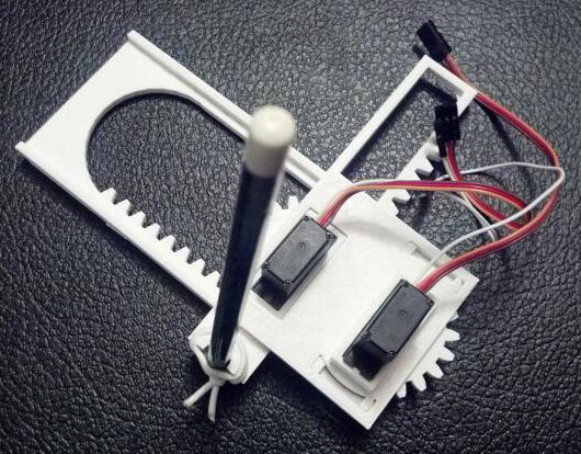
- A new gondola
- A way to mount a roll of paper to my project box
- Besides tearing my drawing robot apart, this is the one thing I did manage to design, print, and put together over the weekend. Since the paper roll I’m using did not come with a center of cardboard or wood or on any kind of spindle, it is not an immediately mountable thing. My roll of paper is just that – a really long roll of paper.
- What I wanted was a modular way to mount a roll of paper to the top of my project box so that it could be adjusted to fit different diameters and widths of paper rolls. My solution was to print two “caps” to go at either end of the paper roll, with a hole through them to run a long wooden dowel. The nifty part is where I then bolted two printed plastic tracks to the top of my project box, onto which I can slide a plastic arm which the wooden dowel fits into. Once the two plastic arms are in place, they can be tightened down onto the plastic track. The result is a rock solid paper roll mount that lets the paper roll freely turn. I was so happy with the way this turned out I almost couldn’t see straight. Yes, it is just a mount for a roll of paper – but it is the most solid and polished way one might hope to mount a core-less roll of paper on top of a wooden box.
- A new way to mount the stepper motors to the project box
- Given the amount of time I’ve spent just mounting a roll of paper and obsessing about spools, is it any wonder I haven’t finished thinking about how to mount the steppers? With the first incarnation of my drawing robot I had designed and printed no less than three completely different motor mounts.
- I would like the final version of the motor mounts to be easily adjustable, probably using a similar track/mount system that I used to mount the paper roll. While this kind of solution takes more time to design, the result is a robot that can be quickly and easily improved and adjusted. As suggested above in the spool section, I am leaning towards mounting the motors so that the shafts are horizontal on the plate of the wall. This will let the motors keep a slim profile in the project box and allow the use of a tall spool which will enable more even and uniform reeling and unreeling of monofilament.
- I’m tempted to incorporate a monofilament line guide directly into the motor mount. In the interests of modularity, it makes sense to keep these things separate, but it might just make sense to do this given the limited space I’ve got within the depth of this shallow project box.
I’m undecided whether I want to put a cover on the front of my project box. On the one hand leaving the front of the project box open allows the viewer to peer into the robot and marvel at its simplicity. On the other hand, without viewing the internals all you would see is a box mounted on the wall, a paper roll on top of that, a power cord coming out of the side, and a drawing pen moving by two almost imperceptible monofilament lines. Perhaps I should explore this idea in another long winded post?
Default Series Title


