A single cord convergence point. “Have the two strings meet at a single point, or as close as possible. The moment they separate the math gets really ugly.”
Deal with friction. “Friction causes the pen to drag and lean. If I tell the robot to draw a square corner and it comes out rounded then I know my pen is dragging because it never reached the corner. The pen has to stay at a right angle to the drawing surface. So far I’ve found that having at least three points of contact is enough to eliminate the problem. That’s why I tape my business card to an eye bolt on the bottom of the ring – the bottom edge of the card forms a large contact area with very little friction.”
Be well balanced. “If the pen is balanced wrong it may point up or down. If it points up then it might go dry. If it points down then it might have extra friction when moving downwards, causing the pen to skip and create a dotted line.”
Have an easy way to switch pens. “Not only should it be easy to replace a pen but every pen should “lock” into the pen holder at the same distance and angle from the drawing surface. In order to simplify this problem I only use one kind of pen that comes in many colors.”
Works on a slanted surface. “Works on both vertical and slanted surfaces up to a maximum of 10 degrees.”
My own prior post on ideal characteristics in a pen holder took into account Dan’s number 1, 3, 4 and considered 5. What I failed to consider was how friction can cause the pen to skip or stutter when the pen is mounted at an angle and the pen travels upwards.
Although I started diving into this consideration, but I’m putting all that over-pontification into its own post. This post is really about (a) Dan considered a very important factor in pen holder construction which I neglected and (b) how awesome open source is. My own pen holder would be a terribly complicated mess doomed to multiple revisions had I not had the benefit of being able to review a veritable legion of pen holders used by many many other people in their many many different kinds of vertical drawing robots.
Early yesterday morning I got an e-mail from Make saying that my DrawBot project had been accepted to the “Road to Maker Faire Challenge!” If you check out Make’s latest post inviting applicants for the “Road to Maker Faire Challenge,” you’ll notice the tiny image in the bottom left is from this post. How cool is that?!
Today at work I got an e-mail from the IT department saying everyone needs to set new, stronger, passwords.1 They suggested several things, like:
“tomandjerry” is not as strong a password as “$H2mlf”
“Fishing123” is not as strong as “Fish123ing”
Assuming a black hat hacker is really determined to crack your password, they’re probably going to attack it like they mean it. Let’s assume there’s no defect in your system that allows a cracker to get in without actually entering the correct password. They might try a dictionary attack first, followed by a database of common passwords, but after that they’re left with brute force.
Here’s the most amusing part. Assuming none of the four “passwords” above are in any dictionary or a database of common passwords. Let’s rank the passwords, 1 being the strongest and 4 being the weakest.
“tomandjerry” is strongest, with 11 characters
Fishing123″ is tied exactly with “Fish123ing”, with 10 characters each
“$H2mlf” is weakest, with only 6 characters
The only things that really matter in passwords are that you’re not using (a) a dictionary word or a common password and (b) the length of your password.2
In any case, it’s concerning when information technology professionals don’t understand fundamentals of password security or how a malicious attacker would attempt to compromise a system.
If you’re using a multi-word password, it is possible an attacker knowing this could use a system that combines words – but this doesn’t really save them a lot of time – we’re talking about numbers with 20-30 zeros in them [↩]
A few days ago I found a DYMO LabelWriter 400 Turbo had been tossed into a cardboard box with used toner cartridges and broken printer parts.1 After making sure this really was a box of lost things, I swiped the label printer along with its power cord.
Tiny little printers such as this kind of label writer never use inkjet cartridges or require laser cartridges. They print using heat – like receipt printers. The catch, since they can’t get you with inkjet/toner cartridges, is that the labels are stickers with specially treated heat sensitive non-sticky sides.
Ideally, I would love to feed this little printer some cheap receipt paper and run it as a small, cheap, USB tethered printer. I already have an Adafruit IoT printer, which I love dearly – but it would be awesome to have one that my daughter could use. Apparently this has already been done more than once.
After loading up the newest drivers for the printer and trying out the newest software for it, I couldn’t get my laptop running Win 7 to recognize the printer. I’m looking forward to tinkering with this. :)
WORKED: The fit. I’m really happy with how the pen holder went together. It’s always very satisfying to print a part you just designed and have it “just fit.” With the zip tie holding the micro servo in place, neither the micro servo tab nor the zip tie protrude beyond the flat surface of the pen holder. The groves for the rubber band to hold the pen in place work very well. The pen doesn’t move side-to-side, get pushed back into the holder, and it is very easy to reposition the pen or change pens entirely. While it’s not as elegant as, say, a metal spring, it works very well and doesn’t require a bunch of moving parts.
WORKED: The amount and placement weight. I hot glued a AA battery to either side of the pen holder, as close to the center as I could manage around the hole for the pen. This weight seemed to work perfectly. There was enough weight that the cords hung in straight lines, but not so much that it seemed to cause a strain on the motors. The placement of the weights seemed to work well as there was no noticeable pendulum swinging of the pen holder, despite me running the robot at about three times it’s usual top motor speed and about twice it’s normal acceleration.1
WORKED: The multiple points of cord attachment. Having a row of holes for connecting the cords at different points along the top central edge of the pen holder worked out great. To test the balance all I did was stick a small paperclip through a hole. If the holder balanced with the flat edge upright and vertical, that’s the point I needed. It was easy to find the balance point and easy to connect the cords.
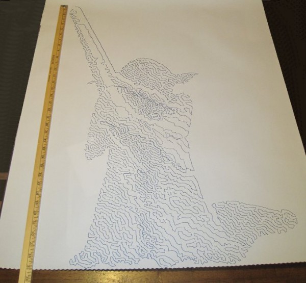
WORKED: The single point of cord attachment. When I was using a crappy cardboard pen holder with cord attachment points very far apart, the entire pen holder would tip to one side or another when it got close to that side. This caused a bubble-like distortion effect towards the edges of the drawing. While this could be a cool effect to intentionally inflict on a drawing, it’s not what I was going for with that crappy cardboard design. Having the two cords meet at exactly the same point worked out incredibly well. Even when the robot was drawing the top left corner of Yoda’s lightsaber, the pen holder was always perfectly vertical.
WORKED: Shape of pen holder flat side. The pen holder I’ve designed is roughly teardrop shaped, with a flat top. My thought with giving it a “flat top” was that it wouldn’t potentially develop a central raised point (between the circular top edge of the pen holder and the device I was using for the pen lift) when I was doing a pen lift. I figured that if I was using a “flat top” it was possible for the pen holder to be balanced on the edge of the flat top and the point of the servo arm – essentially turning my full contact pen holder into a three point contact pen holder with the servo arm as one of the points.
DIDN’T WORK: Motor skipping? There is a large section in the middle of the drawing of Yoda, pictured above, that looks like it was shifted downwards slightly. This could have been because I was fussing a little with the robot while it was working. It could also have been because I was running the robot pretty fast (motor speed of 1600 when the normal is 600), because I had increased the acceleration (400 instead of the default 800), because I had the pots turned down too low (maybe, but the current settings have worked reasonably well for other drawings), because the pen holder was too heavy and causing too much strain on the motor (very unlikely since this holder is lighter than the cardboard abomination I was using) or some combination thereof. My guess is that I probably need to increase the pots when I increase the speed. It’s really unlikely that the pen holder itself was to blame for these missteps.2
DIDN’T WORK: The pen lift. I haven’t drawn anything with a pen lift yet – but I did test the pen lift last night after Yoda was done. I noticed a few minor problems with the pen lift – but nothing to indicate I was on a completely wrong track.
The first problem is that I glued the two batteries slightly too close to the clearance area for the micro servo arm. This is why the next version will include a holder for the AA batteries – to ensure they don’t get in the way.
Second, even when fully extended the servo arm didn’t push out far enough to cause the pen tip to lift off the surface of the paper. This could be solved by either making sure the pen tip is positioned slightly farther back, extending the servo arm, or creating a servo arm powered cam, similar to Dan Royer’s Makeangelo (check out the video at about 4:35 for a view of the cam in action).
Third, my concern is that since the micro servo is mounted in such a way that the servo arm sweeps from right to left, it could cause a similar sweeping motion to be applied to the pen tip – assuming I work out the pen tip depth issues. It’s possible that sweeping the arm upwards or downwards might minimize this effect. I just have no idea whether this is a valid concern or not – the servo arm might move so quickly that it’s not a real concern.
Also, while not an actual issue, the servo motor cable applies a bit of weight to the pen holder. This will require me to reposition the cord attachment points – and may require me to add extra weights to the pen holder itself.
Once I change the pen position and maybe use a larger servo arm, I’ll try a vector drawing which requires pen lifts and re-evaluate this design. Overall, this design has basically worked beautifully. I’m looking forward to experimenting with some new variations on the design to see if I can eliminate the few remaining issues.
Default Series Title
I’ll pretend I was doing this for a system stress-test, but really I was impatient to get a big giant Yoda drawing [↩]
Last night I connected my newly designed pen holder to my finished drawing robot and attempted a relatively “quick” drawing of Yoda. I say “quick,” because it only took about two hours. The one lone trade-off for having an cheap and easy to build robot capable of essentially unlimited drawing sizes is that it can take a long time. I took several photographs of my robot while it was drawing and turned them into an animated GIF, featured at the end.
Finished and mounted robot, with old pen holder
Above is the robot itself, mounted to the wall. I’ve made two minor changes to this setup since that photo, detailed just below. First, I’ve placed a large sheet of sacrificial cardboard under the paper so that any pen leaks will not mar the wall. Second, since the “home point” (exactly 130mm down from the exact midpoint between the two spots where the cord leaves the project box) is hidden by the paper when I pull it down, I needed a way to be able to center the robot without having to re-measure the home point each time. My solution was to take a small piece of leftover plastic about the size of a pinhead and tape it to the home point on the cardboard. Now, I can feel the home point through the sheet of paper and center the pen holder accordingly.
Home point for centering the pen holder
It’s a little difficult to make out in the photo above, but you can see the two big arrows pointing to the home point and a slight bulge in the tape caused by the small plastic speck.
Brand new pen holder, assembled
This picture shows the pen holder fully assembled. I operated it the first time without the benefit of a servo motor cable. I wanted to see if the pen holder would work well. Once the drawing was about 2/3 done and I was pretty happy with the pen holder’s operation, I soldered up a cable to connect the servo lift port to the servo motor.
Drawing robot in action
The above animated GIF is comprised of eight separate photos from my digital camera on a tripod, combined in GIMP. I’ve never to make an animated GIF from a series of photos, but it very quick and painless. Since video takes up a lot of space and battery power, I figured a series of photos would be the easiest way to create a “time lapse” of the robot’s operation. You don’t get the low drone and hum of the motors, but you can see how it operates. Now that I’ve done one, I’m looking forward to making more of these.
Yoda, standing tall
And here is Yoda! As you can see from the ruler next to him, he’s about 35 inches tall from the tip of the lightsaber to his feet. There’s a “band” of the drawing that appears to be shifted downwards slightly, causing a little overlap at the bottom of that region and a slight gap above. This is probably due to me fiddling with the robot, but it could also be due to the motors slipping or skipping slightly during operation. If it was due to me fiddling with the robot, then the fix is simple – I just need to be more patient. If it was due to the motors skipping steps, then turning up the pots just a little would probably fix that. Given that this is the very first drawing from my very first draft of a new pen holder, I’m really happy with the result.
I admit it, I’m prone to verbosity. I wrote 2200 words just discussing the kinds of pen holders other people have used and another 2300 words talking about what I consider to be ideal qualities in a pen holder.1 In some ways, the pen holder is possibly the least important part of the entire robot. When you can use something like a binder clip or cardboard, hot glue, and dead batteries to create really amazing drawings, it’s almost a waste to spend any time thinking about what makes an idea way to hold a pen. However, since I’ve got the rest of the robot looking and working just like I always wanted, I’ve latched onto this last part as something I would like to optimize.
Above is an OpenSCAD rendering of a pen holder I’m getting ready to try out. As I type these words, my Replicator is a little over 50% done printing the pen holder. Before my threemostrecent posts discussing pen holders I had been working on an overly complicated, multi-part, pen holder. It consisted of several pieces that would be printed simultaneously, several spots for captive nuts – the features went on and on. Don’t get me wrong – a pen holder like that might be genuinely great – but I’m not sure that level of complexity is necessary or in any way worth the design time.
The design pictured above meets several of my criteria for an ideal pen holder. For your consideration, I submit the following features, design choices, and design elements:
Just one very lightweight part. This printed part would require only a rubber band to keep the pen in place and, if you’re using a micro servo, a single zip tie to keep that in place. At the moment the design doesn’t include a space for weights. Once the part is done printing, I’m going to put it together with the micro servo and pen and see how it hangs. If it looks okay, I’ll hot glue some batteries to it in various spots. If that works well, I’ve already got a variation on this design which includes some printed tabs for adding dead batteries for weight. The part itself uses very little plastic and prints fairly quickly.
“Full contact” stabilizer. In a prior post I discussed the several types of pen holders and how they can have a single point of contact with the drawing surface, three points of contact, or “full contact.” While the Polargraph style pen holders use a blank CD (120mm in diameter), the above just uses a mostly round shape 80mm across. I don’t know if this is wide enough or not, but this is a first draft.
Pen held at angle. Felt pens and markers don’t really require they be held at an angle, but I can’t imagine it would hurt. Well, I suppose they could have too much ink come through – but I could just run the robot a little faster. There’s no science behind my choice of the pen tilt at a 15 degree angle, it just seemed like a reasonable number. Since it’s a parameter in the OpenSCAD file, I can easily go back and change it if this is just a terrible choice.
Cord attachment points #3, the “Single cord convergence point, not at the pen tip.” This pen holder is designed to allow the cords to essentially meet at one specific point – namely one of the tiny holes in a row along the top edge of the pen holder. These are most visible in the top left of the above picture.
Centering point viewer. Since the cord convergence point is centered on one of those tiny holes, the user of this pen holder can look through a tiny hole the the flat surface of the pen holder to make sure the pen holder is properly centered and homed.
Multiple points of cord attachment. Depending upon pen type, pen weight, and pen holder weight and distribution I could imagine there might be different optimal points of cord attachment. The top edge of the pen holder has a series of holes through which the cord could be fed. The way to attach the cords would be to create a small loop in the end of the cord, feed it through one of the holes and then hook it onto the protuberance at the end of the row of holes. (You might have to look at the top left picture a bit to notice this bit). The other cord would be fed through the same hole – just on the other side and hook onto the same protuberance. This setup was inspired by Dan Royer’s multiple point of attachment set up and the AS220 labs “clip stabilizer.”
Pen held securely in place and depth. A rubber band should do the job of keeping the pen in place nicely. I added a groove to the top edge of the holder where the rubber band can rest. I can’t imagine needing a cord attachment point as far back as the groove near the pen holding cylinder, so I fully expect the last four or five holes can be eliminated, which means I can use the groove around the pen holding cylinder as it was originally designed – to serve as the resting point for the rubber band.
Multiple pen diameters/pen lengths. Although this holder was designed for a pen with a maximum radius of 20mm, it could probably accommodate up to 25-30mm. All but one of the pens in my house would fall in the sub-20mm-diameter category. The reason for having the rubber band point so far back along the pen is that most pens are tapered towards the marker tip, which means you can’t really hold the pen any closer than 20-30mm back from the tip. The holder is designed to hold the pen 30mm back from the pen tip, which is enough to accommodate all but the absolute largest marker.
Holder for micro servo. The holder was specifically designed for my micro servo. Once the micro servo is inserted (in the orientation shown by the shadowy looking micro servo in the images above) one of the tabs for the micro servo sits completely flush with the flat side of the pen holder. There are holes on either side of the micro servo through which a zip tie can be fed. There’s even just enough clearance so that the zip tie itself doesn’t protrude past the flat surface of the pen holder.
Clearance for the widest servo arm. I know many others have designed much better mechanisms for having a micro servo perform a drawing robot pen lift. Since this is literally my very first attempt to incorporate a micro servo into one of my drawing robot projects, I figured I would just use a bare-bones approach and have the servo’s arm directly push the pen holder off the drawing surface. I’m positive there are more optimal ways to do this but again, this is a first draft.
I’ve uploaded the files to Thingiverse, to be followed by my janky OpenSCAD file. It started off totally parametric and then as I got close to finishing it, I just started entering in numbers that would make it work. I’ll go back and improve it, but for now I’ll share what I’ve got.
Default Series Title
I haven’t even started blathering on about different kinds of pens! [↩]
Before we can talk about how what makes a good pen holder, we have to agree on some of the terminology:
Pen holder. This is just the device that holds the pen and hangs down against the paper for drawing. While it is sometimes called a “gondola,” I’ll refer to it as “pen holder” in this post.
Cord. Different drawing robots use different methods for controlling the gondola. Some use monofilament fishing line (as is my preference), others use toothed belts, some use beaded cords. For ease of reference, I’m just going to use the word “cord” to refer to whatever method might be used to connect your pen holder to the motor spools/sprockets.
Hanging triangle. When you draw an imaginary line between the two stepper motors, the cords from each motor meet at a point on the pen holder, forming a triangle pointing downwards.1
Cord convergence point. The “cord convergence point” is the, sometimes imaginary, point where the two pieces of cord meet to form the tip of the hanging triangle. Many times the cords don’t actually physically meet. In those cases, the “cord convergence point” would be the point where the two cords would meet if both cords were perfectly straight lines that continued through their point of attachment to the pen holder.
Up / Down / Left / Right. These directions will assume your robot is mounted to a wall/large sheet of plywood and you are facing the wall. ((This could cause a mention of a “pen up” to be confusing, so I’ll try to avoid this phrase))
Forward / Back. Again, assuming you are facing a wall on which the robot is mounted, forward here would mean going towards the wall and back would mean moving away from the wall.
Without further ado, a list of ideal qualities in a drawing robot pen holder. While not in any particular order, I’m listing them by number for ease of reference later.
Secure pen holder. The pen holder must, as you might imagine from it’s title, hold the pen used for drawing. If it doesn’t hold the pen securely, you’ll get squiggly lines when you don’t want them and really squiggly lines when you only want somewhat squiggly lines. It is important to note that a pen should be held securely so that it doesn’t move around left/right/up/down or back and forth. Even if a pen is held securely with respect to left/right/up/down, it could still accidentally be pushed back (or, I suppose get pulled forward?) causing the pen to not touch the drawing surface (or always touch the drawing surface) despite pen lifts.
Adjustable pen holder diameter. An ideal pen holder should be able to hold a big fat marker or a teeny tiny marker.
Adjustable pen position. I’ve noticed that some pens are a lot narrower near the pen’s tip. Thus, some pens will need the pen tip to be closer or farther from the wall, depending upon it’s own characteristics.
Adjustable tilt to pen. Although markers can pretty much draw at any angle, other pens (such as ball point or gel ink) just won’t work when they’re nearly horizontal.
Incorporate a micro servo. Single line drawings are really awesome – but with the addition of a micro servo for pen lifts, the robot becomes infinitely more versatile.
“Depth” of pen holder. Just to choose a term, this would be the distance the pen holder sticks out from the wall. To strain the metaphor, the “shallower” the pen holder the less it can tilt or tip front/back or up/down. Conversely, the “deeper” the pen holder, the more it could tilt or tip as it moves.
Distance of center of gravity from wall. This is an interesting one. When I started building my robot, I thought the best thing to do was to have the wires leave the project box as close to the wall as possible – so that they would “encourage” the pen holder to hang closely to the wall. Then I realized that it was actually equally important to achieve a balance of the pen holder. With most of the considerations here, I can pretty much determine whether it is better to choose a configuration one way or the other. Unfortunately, with this issue, I can’t decide whether it is better to have the pen holder’s center of gravity close or far from the wall. Of course, not knowing won’t stop me from pontificating, eh?
First, let’s agree there’s no apparent benefit to having a pen holder designed so that it is “deep” and balanced such that the center of gravity is farther from the wall.
Second, the only apparent benefit I can think of to have a “shallow” pen holder is that it might reduce tipping/tilting somewhat.
Adjustable line attachment points. As the weight of the pen holder changes, so would it’s center of gravity. Thus, the attachment points should also change.
Adjustable weight. Weight is one of the more finicky variables. If the pen holder is too heavy, the motors will have a harder time, require more power, and be noisier. If the pen holder is too light, there may not be enough pressure against the drawing surface, the cords may not be held taut (and thus will not behave as the program expects them to), it won’t be as responsive to the tugging of the two cords, and will tend to tip up or down or bind against the wall.
Balanced pen holder. An ideal pen holder should be balanced so that it doesn’t want to tilt left/right, up/down, or forward/back.
In this video from Darcy Whyte’s site you can see how a pen holder that appears to not be balanced well tends to tilt or tip in response to a change in direction – essentially pivoting around the pen’s tip. When this happens the pen either doesn’t move as much as the program expects causing certain features to be too short or the lines and curves drawn will appear to have a “stuttering” quality caused by the pen not moving with the cord because the pen tip is binding against the wall and then releasing suddenly and going too far.
I used to think it would be more advantageous to have slightly more weight on the forward side of the pen holder – now I’m not so sure. What I used to think was that by having the front end of the pen holder heavier, it would somehow exert more force on the wall. However, there really isn’t any logical reason this should be the case. Or, until I put a force sensor on the wall and test it, I don’t think I can claim this to be the case. Watching videos of drawing robots and my own drawing robot in action, I now think that a very light touch on the wall might be more ideal. Let’s assume any decent pen, especially markers, aren’t going to require a lot of force to leave a mark. The more force with which the pen is pressed against the wall, the more likely the pen tip is to bind against the wall and draw stuttering lines or lines that are too-short. Meanwhile, a very well balanced pen holder that is lightly pressing against the paper should not bind at all, resulting in more accurate lines.
Points of contact. There are any number of different designs for pen holders. Some of them only touch the drawing surface with the pen tip (like the Der Kritzler, AS220 Labs and GarabatoBot), while others tend to have three points of contact (such as Makeangelo 1 & 2), and some basically have a large wide flat surface which meets the drawing surface (Polargraph, Mr. Drew, and DRBO). My original mis-use of John Abella’s pen holder design actually had two points of contact – the pen tip and then the sack of batteries that hung from the holder. A few comments about these different styles:
One point of contact. This single point of contact will always be either the pen tip or device used to create a pen lift. Either way, the resulting pen holder can easily tilt left/right, back/forward, up/down, or any combination no matter how well balanced. If you’re going with a single point of contact design anyhow, I suspect a well balanced and “deep” pen holder might work best. Here, by deep, I mean a pen holder that sticks out from the wall. My suspicion is that dialing in the pen’s balance, you might be able to achieve a favorable angle of pen-to-paper. Having a “deeper” pen holder would allow more room for the robot operator to adjust the cord attachment points.
Two points of contact. This is just a bad idea – just don’t do it. The way I implemented this involved a weight hanging below the pen tip. When the pen moved too fast, the weight would swing causing a pendulum like wobble in the drawing.
Three points of contact. This seems, intuitively and by observation of Dan Royer’s videos, to be a stable pen holder design choice. The two extra points of contact (in the case of Dan’s Makelangelo below and to either side of the pen tip) prevent the pen holder from tilting back/forth, left/right, or even up/down. A three point of contact pen holder could still have a sway left/right problem, but that’s so bad if it means you’re eliminating all that tilting.
Full contact. This setup, like the three point contact, eliminates any form of tipping and is possibly less susceptible to left/right swaying. Unlike the single point of contact setup, I think this kind of pen holder might benefit from being shorter (as in doesn’t stick that far out from the wall)
…can be drawn by something as ugly as this
Cord attachment points. There appear to be about several different ways of approaching cord attachment to the pen holder.
The cord convergence point is exactly at the pen tip. This kind of setup requires nice big bearings or metal tubes that allow the cord attachment points to rotate around the pen tip. As the angle where the two cords meet changes, the two cord attachment points rotate to accommodate. Getting the cord convergence point to be centered on the pen tip is much more complicated to design and expensive to build. Look to the Polargraph and Ragnar drawing machine for examples of this type of design. This is particular design choice does not introduce any distortion.
Off-center but close together. This is a very simple and extremely common method of cord attachment. Each cord is connected to the pen holder a little to the left and a little to the right of center with the pen usually a little below that. As long as the two cord convergence points aren’t really far apart, this method will introduce very little distortion. Additionally, by having the two cord attachment points separate, this kind of pen holder enjoys a little extra stability.
Single cord convergence point, not at the pen tip. I have not been able to find any pen holders that use this method of cord attachment. It would basically involve using a single point of cord attachment, either by simply tying the two cords to the same point or by using two pivoting arms as with the Polargraph or Ragnar drawing machine. Rather than the pen tip being at the same point as the cord convergence, the pen tip would be at some point a constant distance and position from the cord convergence point. I think the reasons this type of holder isn’t seen is that it is so easy to build an “off-center but close together” style pen holder, any distortion with the “close together” method is extremely small, and having the cord attachment points separate provides the added benefit of a little extra stability against tilting. However, as long as stabilizers (three point of contact or full contact) are used, there shouldn’t be any reason not to employ a single cord convergence point.
Devil-may-care. The big Deathstar at the top of the post was drawn by the ridiculously crude pen holder pictured above. Even with the cord attachment points being 120mm apart, the results are really great.2 Building a pen holder with this design choice will introduce some distortion. It’s unlikely someone is going to be as foolish as I was to build a pen holder with cord attachment points as wide as 120mm. However, even in such an extreme case, the distortion was shockingly small.
Location of weights. While I haven’t done any tests on this, I’m fairly certain that having the weight of the pen holder as tightly packed around the cord attachment point as possible is most advantageous. The last thing you want is for an off-center weight to cause the pen holder to sway during a direction change.
Enough talk! I think it’s time I start actually designing a pen holder!
Default Series Title
This is a term I only learned today from the context of Sandy’s comment in an earlier post. This term is just so perfect and useful in describing drawing robot set-ups, I just have to include it here. [↩]
Unfortunately, the Sharpie started to run out of ink about 2/3 through the picture, which does detract from the drawing somewhat. [↩]
In discussing Sandy Noble’s Polargraph pen holder I mentioned how his design is optimized so that the point where the two cords meet is always the same as where the pen tip meets the paper.1 In the comments, he explained his rational, “So the pen tip is always at the tip of the hanging triangle, and there’s no distortion that way.” My response was that “…if the pen holder has a single ‘hanging triangle’ point in it with the pen tip a constant distance from that ‘hanging triangle point,’ the drawings should appear identical to those created at the ‘hanging triangle point’ – just offset by the constant distance.”
Without as much fancy-schmancy maths and geometry, I figured I would explain the thought experiment I used to conclude that a pen tip that is always a constant distance and position from the “hanging triangle point” will always produce an accurate distortion-free drawing. To help illustrate these thought experiments, I’ve enlisted the help of Yoda. “Hi Yoda!”
Fig 1: Yoda, being drawn by a drawing robot
In the picture above, Yoda is being drawn by a drawing robot.
Fig 2: Yoda drawing, annotated
Above, I’ve labeled the important parts of the drawing. On the top left “Motor A,” on the top right “Motor B,” which are attached by cords to the pen holder indicated by the dark blue line. Here, I’ve shown Yoda as he would be drawn by a drawing robot, where the robot then draws two more points.
Let’s say, because we’re feeling whimsical today, we want to add a second pen to our pen holder. We’ll use a red pen and affix it below the blue pen in such a way that the red pen will always be directly below the blue pen by the same distance.
Fig 3: Another pen
For the moment let’s pretend the red pen is capped so it won’t leave a mark. Now we’ll try to predict the position of the red pen at different points along the original drawing.
Fig 4: Where’s the red pen?
It turns out this task is pretty easy. The red pen, at any given point during the Yoda drawing, will always be directly below the blue pen by the same exact distance between the two pens. Okay, now let’s draw Yoda again – this time with the red cap off.
Fig 5: Double vision
We get two Yodas! How awesome is that! The reason I mentioned calligraphy pens in the title of this post is because it shows another way to think about this process. When we write with a calligraphy pen we don’t have one end of the pen wildly distorted – in theory the two points on the calligraphy pen are always a constant distance from one another and moving together (as long as we don’t rotate the pen when we write). You could imagine instead of a blue and red pen above, we’ve put a single calligraphy pen that’s as wide as the black line representing the distance between the two pens above. The resulting drawing would look like a Yoda – that had been smudged downwards by the same distance.
Let’s now draw Yoda again, but capping the blue pen and still tracking where the blue pen would be.
Fig 6: Not using the blue pen
We should end up with a result very similar to Fig 4. It’s the same Yoda, only red and shifted down from the original blue Yoda by the distance between the two pens.
Let’s draw Yoda again – this time we’ve still got a pen holder which has the cord from Motor A meet Motor B at exactly one point. As Sandy points out, this is really easy to do when you aren’t worrying about making that exact point be the same precise point as the pen tip. Directly below point where the two cords meet on the pen holder, we’ll put the red pen. From a functional standpoint, this setup is identical scenario to Fig 6.
Fig 7: Drawing just one red Yoda
Now we have a red Yoda, shifted down on the paper by the distance between the point where the two cords meet and where the red pen touches the paper. It’s important to note that there’s no special magic to having the red pen directly below the point where the cords converge. This pen tip just needs to be a constant distance and position from the cord convergence point at any given time. While it might be more difficult to build a pen holder that holds the pen far off to one side, there’s no reason this wouldn’t work.
Fig 8: Yoda, now in green
The lessons I take from this thought experiment are:
As long as the pen is a constant distance and constant position from the point where the two cords meet, your drawing will not appear distorted – just shifted by the same constant distance and position.
When calibrating the robot, the operator would need to calibrate the pen holder position by the cords convergence point – not the pen point. This means that the preview in your software won’t match exactly the position of your drawing on the paper.
While not part of the thought experiment per se, I think we can all agree that the more weight that is not centered on the cord convergence point, the more likely the pen holder is to sway.
I’m willing to defer to Sandy’s experience that pen holders that do not have the cord convergence point the same as the pen tip are, “Easier to design, easier to build, and cheaper, far, far cheaper.”
Thanks Yoda!
P.S. Just in case you’re wondering – the reason that SVG of Yoda above is so large is because it includes the full TSP version of Yoda I’m getting ready to draw. :)
Before Maker Faire announced the official call for Makers, I had already downloaded and printed out the “call for Makers” information from the most recent Maker Faire and handwritten all of my responses in the form – just so I would be ready to submit my application to be a Maker this year. ((Photo courtesy of @Doug88888)) I ended up submitting my application within just a few hours of the call going out.
After I had submitted my application, my daughter wanted to submit her own application. Of course I was happy to help her, so I helped her prepare an application and submitted it on her behalf a little after 11pm on March 14, 2013, just under the wire.
Today Maker Faire sent her an acceptance! My daughter is going to be exhibiting at Maker Faire Bay Area 2013!
.
..
…
I just hope my acceptance letter comes soon. :/ Senior year all over again…