
Back on track

Good news!

Okay, as of 11:30 AM, the AC was working again and battling against 104 degree heat.  That means we can start looking at our data again – and plan out what to do about the window, sun shade, or other system for blocking some or all of the heat for this one picture window.

In an effort to help make this data more representative of what’s actually going on inside the house, I put a thin piece of aluminum around the sensor in the entry way.  My thought was that it would help deflect some of the direct heat hitting the sensor and causing it to register ~100 degree heat on the ground.

Distributed temperature sensors for creating a “heat progression map” of temperatures in a house.  Right now I only have three sensors, but these are inexpensive enough, that I could see creating several to send temperature back to my PC.  There’s always a tradeoff between effort, speed, and cost.

  • One infrared thermometer.  $15
  • One board, 3 sensors, lots of wire.  ~$30 and lots of wire hassles
    • $5 XIAO board, $2 worth of thermistors and resistors, $2 protoboard, $15 wire
    • A small amount of soldering
  • Three boards with a sensor each.  ~$25 and very portable / placeable
    • 3x ($3 Wemos D1 Mini, $2 AHT10 sensor, $2 protoboard, $1 tap light, $1 for two AA batteries)
    • SO MUCH SOLDERING

For the best looking and most useful data, I think the three-board but higher effort approach is best.  It also scales very nicely.  For about $50 you could distribute 6 sensors throughout your house and get a sense of how heat moves around you home.

Summer Science - Testing Effects of Window Coverings on Interior Temperatures
  1. Testing the Effect of Interior and Exterior Window Coverings on Interior Temperatures
  2. Testing Interior Temperatures – preliminary results
  3. Readings so far… 07/11/2026
  4. Now with remote sensors
  5. Repeatedly Redundant (Sensing Sensors)
  6. WHY IS EVERYTHING BROKEN?!
  7. Musings on measurements and a wacky cat
  8. WWMWD?
  9. Back on track
  10. House Temperature Readings So Far

Repeatedly Redundant (Sensing Sensors)

This is the second time the XIAO board stopped working for an extended period of time.  Rebooting the board, unplugging/plugging the power cable and adapter from the wall, and even pulling the board from the headers, didn’t work to get it back online.  I finally pulled the board, plugged it into USB, then made a do-nothing change to the main.py file1 and plugged it back into the headers, which worked perfectly.  There were no obvious errors in the board – it just … needed a boring update to the code?

This slideshow requires JavaScript.

Anyhow, I’d discussed some of the pros and cons of running three Wemos D1 Mini powered sensors2 versus just one XIAO ESP32C3 powered sensors – but didn’t think about what happens when a single one goes down.  Although the XIAO was out of commission, the three Wemos board kept going so I didn’t really lose any temperature data – especially since the data was so flat during from 12:30 AM to 9 AM this morning.

Admittedly, the locations for the three sensors aren’t perfectly matched.  I have the three XIAO thermistors taped to the entryway flooring, taped to the metal plate just inside the family room, and one dangling in the air above the entryway out of any direct sunlight.  The three Wemos AHT10’s are on the entryway floor near the entrance to the family room, well inside the family room on the mantleplace, and the last at the top of the stairs with the sensor in open air at almost the exact same height and area as the original XIAO ambient sensor.  I actually wanted the second XIAO sensor over on the mantleplace as well – but didn’t want a run wires across the house that far to do it.  I’m at peace with getting different readings from these sensors versus my historical readings because:

  • The AHT10’s are supposed to be more accurate – and also measure humidity which I’ll use near my 3D printer later on
  • There’s no really good way to tape the AHT10’s to a surface and that doesn’t really tell me much about the “feeling” of warmth inside the house anyhow
  • The floor readings were constrained by the amount of wire I had rather than really wanting measurements at those specific locations

Just looking at the charts of the incoming data suggests that the AHT10 sensor data is definitely less noisy than the thermistor data.  Then again, it might be due to the way in which I’m taking readings every minute but then broadcasting  the data every 5 minutes.  I’m sure no one would notice or care if I sampled the data every 5 minutes, but when the peak heating coming in from that one picture window only lasts about 30 minutes, I think I’d like to get a better sense of what’s going on minute-by-minute rather than at 5 minute intervals.

Summer Science - Testing Effects of Window Coverings on Interior Temperatures
  1. Testing the Effect of Interior and Exterior Window Coverings on Interior Temperatures
  2. Testing Interior Temperatures – preliminary results
  3. Readings so far… 07/11/2026
  4. Now with remote sensors
  5. Repeatedly Redundant (Sensing Sensors)
  6. WHY IS EVERYTHING BROKEN?!
  7. Musings on measurements and a wacky cat
  8. WWMWD?
  9. Back on track
  10. House Temperature Readings So Far
  1. Changing something behind the comment line from “#==================” to the same thing with one less equal sign []
  2. Way more than triple the soldering []

Now with remote sensors

As with many of my projects, the scope and build has changed somewhat over time.  This project started with me just taking readings around my house with an infrared thermometer at somewhat regular intervals.  However, this was tedious and prone to variance as I measure things by hand.  After that, I started using a single XIAO board with three hardwired thermistors around our entry way.  The nice thing about this kind of a setup is that I really only have to build/program one board, set it up, and then let it send data to my PC.  The downside is that there’s wires everywhere – and it used up my entire stash of glorious rainbow colored ribbon cable. 1

Practice when I work on a project is to buy replacement parts for the pieces I use up after I’m done.  This way, I will still have stuff on hand for my next project.  So, I’ll need to pick up more colored colored ribbon cables, small solderable prototyping boards, and replacement microcontrollers.  Back in the day, I would stock up on Adafruit Trinkets, but for about a lower price and a slightly larger footprint, I can get a XIAO board with more IO ports, memory, speed, and built-in wifi/bluetooth.  The little prototyping boards I’d purchased aren’t available from the same seller on Amazon, which is too bad.  I really like these boards because they’re bigger than just the microcontroller, have power rails that run down the center rather than the sides and horizontal rows, and rounded corners.  They’ve been incredibly convenient.

With this project, I wired up three Wemos D1 Mini boards, each to a different AHT10 temperature/humidity sensors, and shoved them into my favorite enclosure – cheap tap lights.2

This slideshow requires JavaScript.

As I’ve mentioned previously, I’m just not very good at soldering – which is why I go very slowly, checking, rechecking my progress as I go.  Even so, I made two small and fixable mistakes, soldering the wrong connection somewhere and later accidentally bridging two contacts.  Fortunately, some things are fixable.

The construction of these little wifi sensors isn’t very interesting.  Rather than run each board off of 4.5 volts from three AA batteries, I’m using 3.0 volts from two AA batteries.  By not passing that 4.5 volts through the voltage regulator to bring the power down to 3.3 volts, I should be able to save enough battery life to justify running this system off 2/3 the batteries.  This meant I soldered the power connectors to the end and middle battery connectors.  I have a suspicion that the XIAO boards are probably more power efficient, but if I don’t use those Wemos boards for something simple like this, well, I’ll probably never get around to doing it.

In any case, I now have these three sensors throughout the house near the locations of the prior sensors.  I like these AHT10 sensors – but unlike the thermistors, I can’t really get the sensor right up against a surface.  Hopefully it won’t matter much.  While the readings directly off the flooring and metal plate were dramatic and gave a sense of the heat that was being absorbed and released by the house, it’s the actual temperatures in the house that are what I’m after.  In the meantime, I’m running both systems in parallel so I can make sure they’re both pulling in reasonably consistent readings.  If so, I’ll pull down the tangle of wires, wind them up, and set them aside for the next project.

Summer Science - Testing Effects of Window Coverings on Interior Temperatures
  1. Testing the Effect of Interior and Exterior Window Coverings on Interior Temperatures
  2. Testing Interior Temperatures – preliminary results
  3. Readings so far… 07/11/2026
  4. Now with remote sensors
  5. Repeatedly Redundant (Sensing Sensors)
  6. WHY IS EVERYTHING BROKEN?!
  7. Musings on measurements and a wacky cat
  8. WWMWD?
  9. Back on track
  10. House Temperature Readings So Far
  1. I picked up 15 feet for $5 about 13 years ago from Sparkfun, now selling for $7.  Digikey also carries it for quite a bit more, but I haven’t run the math to figure out whether shipping makes a difference. []
  2. With some hunting, you can find a set of tap lights for about $1, they include a battery holder, switch, bright white LED, attractive sturdy case, and semi-translucent top. []

SOLVED! I can’t upload Arduino sketch to Wemos D1 Mini ESP8266

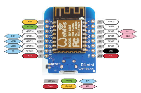
ESP8266 Wemos D1 Mini pinout

My Wemos D1 Mini WiFi boards had arrived from China1 on Friday and I’ve been fiending to build… something with them.

Unfortunately, I couldn’t get the very basic “blink” sketch to upload.  Here were my symptoms:

  • When uploading, I got the “error: failed to open” message
  • My Windows computer flashed a message when I connected the board, saying it was an unrecognized device
  • The Device Manager showed a little “alert triangle” suggesting the proper drivers were not installed
  • All of the ports in the Arduino IDE were disabled and greyed out

I tried several different upload speeds and several different USB micro cables to no success.  It was not until I found this post explaining that I needed to update the Wemos drivers along with a handy link to said drivers.

Now that I got this board blinking, I can’t wait to get it to do MOAR…

Default Series Title

Update:  My buddy Chris pointed out that I’ve been mixing up ESP32 and ESP8266.  I’ve corrected the title now.

  1. $13 for four boards plus headers?! []

ESP WiFi Board Experiments

A friend of mine pointed me in the direction of some ESP32 board tutorials over at MsRaynsford.co.uk.1 You know it’s a fast moving area when a post that’s less than a month old already has a dead link.  :)  Rather than re-creating all the tutorials that are already out there, I’m going to just jot down my notes and links as a short of “quick start guide to quick start guides.”

This slideshow requires JavaScript.

  1. ESP Boards
    1. There’s several different “flavors” of ESP WiFi tech, however it seems as if they all break down into one of three different categories.
      1. Bare ESP WiFi module.  These require a bit of effort to make work since the bare module requires the pins to be broken out to be made useful.
      2. ESP WiFi breakout boards.  This type of board, which has 8 pins broken out, requires a programmer.  Since these 8 pins are arranged in a 2×4 pattern, they can’t be used directly in a breadboard.
      3. ESP WiFi development boards.  These board seem to have lots of pins broken out and typically a USB connector.  Since these boards have more features (voltage regulators, compatibility with other boards’ form factors, USB communication built-in), they’re going to be more expensive.  There’s the Adafruit Huzzah, the Sparkfun ESP Thing, and then something called the ESP Wemos D1.
    2. There are several different ESP modules and boards which have varying amounts of space from 512kb to 4MB and varying amounts of pins from 2 to 24 pins.  These modules all tend to have different names (ESP-01, ESP-07, etc, etc) but are all known as ESP8266.
    3. The ESP modules require 3.3v, so a 5.0v USB or other source will fry them.  Plan accordingly.  Some development boards have voltage regulators on them to adjust the power going to the module.
  2. Correct Board Manager URL for ESP boards
  3. An overwhelming amount of information for ESP boards
  4. Ordering Boards
    1. I’m ordering several boards off of Aliexpress.  I’m getting a few Wemos D1 boards, since they’ll be easy to prototype with2 , and a few ESP-01 breakout boards and a single programmer to toss into a project.  Then again, at <$3 a piece for the Wemos boards and <$2 a piece for the ESP breakouts, it doesn’t make a ton of sense to stretch to put the ESP-01’s into a project.  My thinking is that most any project I build will only use a pin or two and not be too terribly complicated anyhow, so that once it’s been prototyped I can just burn it into the ESP-01’s and permanently install it into a project.
    2. I’m not exactly sure which what WiFi enabled things I’d like to build yet. 3  Here are some ideas:
      1. A pair of tap lights that are connected over the internet.  I’d tap one before I left work, it would flash a color to let me know it sent a message, and the other one at home would light up to let my fam know I was on the way.  I guess it’s similar in theory to this.
      2. A button to call an Uber or Lyft.
      3. A button that will email or call my cell in 2-5 minutes from the time I press the button.  Useful when I know someone who stepped into my office isn’t good at taking a hint.  Or when I need to get off a conference call.
      4. A button that can be used to log simple events.  Might be useful at work in a variety of ways.
      5. A button that will automatically start a print job on my WiFi enabled 3D printer.
Default Series Title
  1. Another tutorial here and here []
  2. Solder in headers, connect via USB, drop in breadboard, prototype away []
  3. Sometimes I will buy a few parts I know will be useful, spend some time tinkering with them, and then later build something when inspiration strikes. []
Test