Confluence

With my MK6 disassembled1 and work projects stacking up, I tend to become more prolific in writing and designing. 2

Whenever my ‘bot is in need of repair, my mind goes back to all of the projects and things I keep meaning to print…  but never find the time for.  I also think back to design problems I was having… and sometimes come up with solutions!

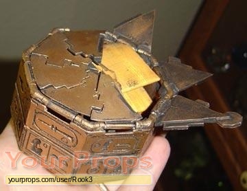
Take, for instance, the puzzle box from The Mummy.  I’ve been meaning to get back to this for more than six months.  Well, an idea for a way to make it spring open just occurred to me.  I could put another octagon shaped box inside of the puzzle box and a flatish spring underneath it, squished between the two boxes.  If the top of the box is released, the spring would force the inner box up – and against the lid components and the entire lid open.  It would also potentially work well with little spring loaded pins just under each of the lid pieces.  I’m thinking something like a piece of filament forced upwards by the spring from a retractable ball point pen.  Or, if your spring was good enough, the spring could be under just one of the lid pieces – with the other lid pieces laying on top of it.  As that one pieces is forced up, it could force the others out.

Without the benefit of my printer running, I’m also putting a few extra brain cells3 on my clockwork spider project.  I was inspired by several things recently.  First is the video of how a mechanical clock works I had posted earlier.  As you’ll recall from Skimbal’s Rubber Band Gear Mechanism/Engine, a wound spring engine will want to expend all of its energy all at once.

That video describing the inner workings of a clock demonstrates a little regular that only lets it unwind a little bit at a time, so it can expend its energy over a longer time period.  Secondly was Erik’s pick-n-place tape feeder.  This design uses an interesting spring/gear/ratchet wheel.  Skip to 1:25 for a demonstration of the mechanism in question.

Now, in the instance of Erik’s device, it is the ratchet that moves back and forth – rather than the wheel turning at a constant rate.  However, this gave me an idea.  It should be feasible to create a similar spring/ratchet combination to prevent a wound device from expelling it’s energy at once.  Last, but by no means least, is Dna’s rubber band ratchet engine designed to power a clockwork spider.

In pondering my attempt at an open source disc launcher, I’ve been trying to think of the best way to pull back the spring.  If the firing pin/slider is going to be powered by a rubber band, it’s going to need to be a decently sturdy mechanism.  I keep thinking back to a rack and pinion set up.  There could be a notch in the bottom of the firing pin/slider, a peg in the flat side of a rack, and a small gear run off of a big gear, with the trigger on the big gear.

What else?  Um, I think the tank by mraiser could make a good platform for a larger clockwork spider.  Also, I would like to see a version of the tank that’s run off of clockwork/gears/regulators/rubber band/springs.

  1. More on this later []
  2. I didn’t say better, mind. []
  3. Both of them! []

Note to self, too

The Mummy Box Set - and detail of box

1. The Mummy Box Set - and detail of box

One of my favorite movies is The Mummy, and the coolest prop in the movie is a hexagonal puzzle box. When I get a chance, I’d like to design this object too. Here are some photos and informative links I’ve found:

  1. The cover of the Mummy Box DVD Set.
  2. What appears to be a homebrew prop replica.
  3. What appears to be an actual movie prop.

Sure, it’s frivolous.  However, I like the design challenge inherent in replicating this prop, getting the pieces to fit, perhaps even getting it to spring/pop open.

Home brew prep replica

2. Home brew prep replica

Mummy Puzzle Box Stats
Measurement of height 6-7/18″
Measurement from front to back 3-3/4″
Measurement of width, all sides 2-3/4″
Measurement of width, corner to corner 2-3/4″
Measurement of height 1-1/2″
Measurement of width, from base 5″
Measurement of all links 1-1/4″
Color Antique Gold
Other design details Top shows Seti I’s Horus name (men-maat-re), flanked by Anubis on the left and a male figure on the right, separated by vertical lines. Sides are inscribed with haphazard hieroglyphs including “Son of Re” and “Amen-Re.”
Puzzle Box - full picture

3. Puzzle Box - full picture

Puzzle Box close up

3. Puzzle Box - close up

3. Puzzle Box - side view

3. Puzzle Box - side view

3x2x1 Rubik’s Cube Production File

My prior copy of this 3x2x1 Rubik’s Cube was printed a few parts at a time – I’d print one part, test it, print up another, etc.  Last night I was able to use my production file to generate all seven pieces in one go.  It took 1 hour and 45 minutes to complete the print job, but well under three minutes to clear most of the pieces of the raft off the parts and assemble the puzzle.  In order to help people modify and improve upon my design, I’ve upload the original Sketchup files, the STL I used, as well as my own GCode.

Owenscenic on Thingiverse asked,

I am interested in trying your gcode, how did you generate it? How well does it minimize strings between the printed parts? I’ll look at is to see how it starts and the temp…

In case you’re wondering too, the answers are as follows:

  1. I generated the Gcode using my slightly tweaked RepG v18 built-in Skeinforge settings for ABS with a raft, with a build temperature of 220C.
  2. The Gcode does pretty well with minimizing stringing.  However, some of the credit has to go with the part placement in the STL production file as well as the nature of the object.  As soon as you assemble it and start to rotate the parts, most of the remaining strings and little blobbies will pop right off.

Owenscenic, please let me know how your print of this turned out!  Please post a picture!

New 3x2x1 Rubik’s cube design – totally printable!

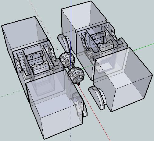
X-Ray view of the 3x2x1 puzzle cube

X-Ray view of the 3x2x1 puzzle cube

This is easily my most intricate digital design for the MakerBot yet.  It’s a 3x2x1 variation on the Rubik’s cube puzzle I had posted earlier.

This version incorporates the prior improvements as well as designing a connector system inspired by R3bbeca‘s beco block connectors.

This has enabled a totally printable toy.  This just makes me happy. 1  The idea that I can crank out a set of these parts, clean them up a little, and just snap the toy together is just amazing.

TomZ‘s original 1x2x3 “friendlier” Rubik’s cube designs were also totally printable – but required a printed pin that was later glued in place.  I like the ideal of all printed parts – but strongly prefer a design that can later be disassembled easily.  And, as I mentioned above – the ability to hand assemble the toy is important to me.

I wasn’t able to recreate R3bbeca’s female connector designs2 so I made a simplified version that should suffice.

The simplified connection mechanism is essentially two plastic fingers that will (hopefully) pinch the barbell into place.  This was made by designing the outline of the gripping “fingers,” creating a horizontal cylindrical hole slightly larger than the intended end of the barbell, then creating a vertical cylindrical hole in the center for the barbell to be inserted through, then a bit of cleanup.

The biggest potential problem is that this design will require a carefully tuned ‘bot.  The center cube pieces have a lot of stuff packed in there – semi-circular slots for the semi-circular tabs, connectors for the barbell, and thin walls separating things.  With those thin walls and interior overhangs, this may be a difficult design to print.

I think Bender is up to the task, but we’ll see in a few hours.  :)  I can’t wait to print this!

For me, having a MakerBot is like waking up to Christmas every morning.

Oh, and before I forget, if you want one of these – leave a comment or send me an e-mail through the Contact page.  Make me an offer.

  1. Perhaps a little prematurely, since I haven’t actually printed this yet… []
  2. I believe I’ve already sufficiently lamented my inability to understand women and their mysterious lady ways. []

A MakerBot printed 3x2x1 Rubik’s Cube!

Lotu's print of the 3x2x1 Simplified Rubik's Cube

Lotu's print of the 3x2x1 Simplified Rubik's Cube

SWEET.  I’ve been so busy of late123 that I haven’t even been able to print several of the things I’ve uploaded. I’ve uploaded several cookie cutters, with another sitting on my hard drive and one more knocking about in my head keeping the cobwebs company.  I’ve also uploaded my variation on a simplified Rubik’s cube.

Well, someone printed it!  It looks AMAZING!  I wonder if it works properly?  I slapped the design together rather hastily after getting frustrated with my MakerBot failing to print TomZ’s 1x2x3 Rubik’s cube.4

I can’t wait to either get some feedback from Lotu (who printed it) or print up one of my own so I can improve on the design.  I’d really like to make a version that is 100% printed – with a snap joint in the middle rather than a nut/bolt system.  If I go down that route, I was thinking about incorporating what I learned from the fantastic Becco blocks connection system by r3becca.

If you print one of these, please answer the following questions:

  1. Which STL did you use?  The one with all 6 pieces or the one with 3?  Would you prefer printing the pieces one at a time?
  2. How well did they fit together?  Are they very snug?  Too loose?
  3. How well does the nut/bolt work?
  4. Did you have to adjust your Skeinforge settings at all?  Why?  How?
  5. Do you have giant hex wrenches like Lotu does?
  1. Mostly writing nonsense. []
  2. Which is particularly funny since my day job consists almost entirely of writing. []
  3. Which is even funnier when you consider that you can tell I’m doing a particularly good job when my writing is completely incomprehensible. []
  4. Did you catch how I swapped all the numbers around to differentiate my derivative?  I thought that was pretty clever… []

New design: Rubik’s Cube (sorta)

Rubik's Cube for Dummies

Rubik's Cube for Dummies

I’ve already posted about how much I like TomZ’s simplified version of a Rubik’s cube.  Only problem is that I wasn’t able to encourage my MakerBot to print it.  Taking into account some of my ideas, I’ve designed a derivative.  It’s 4:45am at the moment – not a good time to have my MakerBot tooting and beeping.  ;)

Here’s what I’ve done with this version:

  1. Oriented the STL so it is immediately printable
  2. Run the STL through NetFabb to make sure it is manifold
  3. Reduced the number of unique printed parts from 5 to 2
  4. Put the STL together in such a way that you can print up two of the STL’s for a total of 6 parts, ready to be assembled
  5. Shrunk-ified the nubs for that fit into the center pieces
  6. Enlargened the grooves for the nubs
  7. Oriented the three parts so that they would use a minimal raft
  8. Changed the design so it will accommodate a nut/bolt attachment system rather than several additional plastic parts that must be glued together

In a future iteration, I hope to change the middle pieces so that all you need to do is snap the two middle pieces together.  Also, I’d like to incorporate any design suggestions from people who have tested this version.

Rubik’s Cube Fail

I just tried to print up the 1x2x3 Rubik’s cube puzzle from TomZ.  I really like the idea of it.

Unfortunately, it’s just not working for me.  I had to rotate all of the STL’s 90 degrees to make them printable.  Once most of the parts were printed I discovered it’s not going to fit together.  The swivelly bits on “Part 1” are too large to rotate freely inside the center cubes.  If the grooves in “Part 2” were much larger it wouldn’t fit inside the part.

At this point, it’s probably easier to start building the entire puzzle from scratch.  Here’s what I’m thinking:

  1. Make the swivelly bits on Part 1 smaller
  2. Make the grooves in Part 2 slightly larger
  3. Make a notch in Part 2 and Part 3 so that it can be put together with an M3x16 nut and bolt instead of a plastic pin