Maker Faire 2026 Project Post Mortem

As time grew close to Maker Faire, we had to sharpen / tighten our goals.  We always try to improve some part of our projects and change things up.  This year, we worked on the more “cosplay” elements and left the more electronic and technical aspects largely alone.

  • ED-E Companion Robot
    • Dexter built an entirely new body for ED-E from a milk jug, 3D printed parts, foam mats, and model magic.  In retrospect, an HDPE milk jug is so smooth and adhesive resistant that it may not have been the best choice.  The paint flaked off in some small places and the 3D printed internal structures didn’t stay in place as desired, but everything held together quite well over the course of the entire weekend.
    • ED-E used to be built into a small 3D printed enclosure, about the size of a baseball, which was limiting for power supply and other mechanical abilities.  This year we mounted him on a PVC pipe, but quickly learned the end needed to be padded otherwise the constant shock of hitting the ground would slowly scramble his brains.
    • I think an entirely 3D printed case is very doable for next year, would take pain much better, permit easier access to his brain, better placement for LED’s and a speaker.  He would probably benefit from using separate ESP32’s for the brain and the PIP-Boy to communicate wirelessly, so that the robot could be easily untethered from the arm.
    • Another issue with the robot was simply carrying the thing over the day.  The robot and PVC aren’t that heavy, but over time lugging it around, even using it as a walking stick takes its toll.  The temporary fix at Maker Faire was to tape a bunch of foam to the bottom of the PVC pipe.  One possible fix would be to design a TPU cap to go over the bottom of the pipe, to cushion the impact of the pipe on the ground – and help reduce the impact on the robot components.  One idea is to add a wheel or caster to the base and another idea would be to put the whole robot on an IV pole.  Putting the pole on a single caster/wheel could be problematic if we needed to set the robot down – unless the wheel had a retractable kickstand or retractable wheel.  An IV pole might work well, but sourcing one might be an issue. 1
  • Vault Dweller
    • I pivoted my project from being solely about a shoulder mounted robot to being more of a “vault dweller with companion robot.”  I designed our PIP-Boys from the ground up, making several changes from other designs out there for aesthetic and practical reasons, while keeping the essential look.  Although I didn’t get around to adding yellow accents to my blue jumpsuit, I was recognized throughout Maker Faire and called out as a “vault dweller” probably due to the icon combination of the jumpsuit and PIP-Boy.
    • My PIP-Boy included the e-ink display I had originally purchased for use in a kind of digital to-do list, but disconnected from a microcontroller.  I’m looking forward to building in additional features to the device, adding a power supply, microcontroller, buttons, and lights to bring it to life.
    • I normally take a sling backpack with me when I’m out for a day trip or running some errands.  However, after the first two days I skipped it entirely since my jumpsuit had ample pockets and storage.  The various vault suits out there don’t seem to include pockets, but that’s just silly.  Ideally, for aesthetics the vault suit would feature some leather / faux leather (possibly weathered craft foam) pads at the elbows and knees as well as a brown / dark brown leather belt with pockets / pouches for stuff.

I’d really like to get a working set of buttons and microcontroller working in my PIP-Boy to be able to change the display.  There’s probably room in the PIP-Boy for a battery pack, some wires going to various LED’s2 , possibly a small servo, potentially a little laser3 , and maybe a little spring loaded projectile launcher.

I couldn’t be happier with how the PIP-Boys turned out.  My 3D designs really came together.  The cuff parts were just craft foam / floor mats and fit reasonably well.  They had a tendency to slip or rotate on the arms a little, but not to a problematic extent.  The 3D printed parts stayed affixed to the painted foam cuffs well enough.  Both were instantly recognizable as PIP-Boys by lots of people.  I think with some sanding, wet sanding, and a blast from a heat gun, they’d look even better.  I’m really looking forward to sprucing these up.

  1. I don’t mind paying ~$10 for a used one, but not interested in picking up a brand new one for $40-400.  I did find one on Craigslist, but the seller hasn’t replied after several hours.  After this afternoon, I’ll be a lot less immediately interested since we probably won’t be suiting up again for another year. [↩]
  2. I have a great spot for the 5mm NeoPixels I bought years ago [↩]
  3. Because, why not!?! [↩]

Smol Fonts for E-Ink Displays

Posts are so much more interesting with pictures, don’t you think?

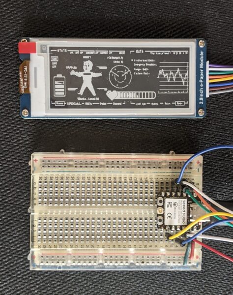
I’ve been playing with different screen designs for my e-ink display.  After initially going with some “to do” style items, I quickly pivoted to playing with some more interesting screens while I was working out the best way to update the display with new content from lists.  This wasn’t a totally worthless chase, however.  Fiddling with various ideas and tests about updating the display and coming up with different images lead me to chase down good looking fonts (Futura variants and Roboto being attractive and friendly fonts) and fonts that look good at very small scale (UNSCII, Tom Thumb, TinyFont for TinyGo displays, and Terminus).  Adafruit has a great toolchain for converting a font from an PC recognizable font to a BDF format font which is much smaller and can fit into a microcontroller.1 It involves2 using FontForge to remove unused glyphs, restrict the font to a specific bitmap size, exporting the font, then using an online tool to convert it to a BDF format.

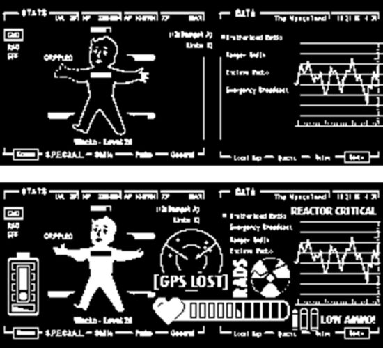
For extra visual interest, here’s the first Fallout themed screen I uploaded and the latest:

Things are not looking up, my dude

The main screen was inspired by the work of CrowTeeRobot on the RPF.  I took a few screens, jammed them together, added and deleted a bunch of stuff.  After all that, there was still a fair bit of negative space, so I kept adding in more things.  A low battery indicator, life point indicator, a GPS lost / map indicator, an increasingly worrying radiation counter, and a “low ammo” indicator.  If these end up getting installed into a PIP-Boy, I’ll probably try to add a green transparency over it to give a more retro feel.

For working with an e-ink display to go into a PIP-Boy, it really only needs to cycle through a set number of screens.  This could just be done by having the MCU just play new screens every few minutes (keeping in mind the Adafruit guides recommend updates be no more frequently than every 3 minutes) or having it be slightly interactive and update the screen way less often (say every 10 minutes) but can be set to a new screen manually by pressing an associated button.  However, this just requires building a few static screens, saving them as BMP files, tossing them in, and letting the MCU detect button presses, capacitive touches, or some other kind of input.  There wouldn’t be any kind of need for a text overlay.  That said, while I was playing with the screen, I discovered that some of the graphic text I had included was surprisingly readable at very small scale.  This lead me back to my main project…

For my note / reminder / task purposes, I’m still toying with how the workflow would go.   Since I want a device that is untethered from a USB cable and has

Here are some ideas I’ve gotten to work and played with:

  1. ESP32C3 as a WiFi access point and provides an HTML form which the phone or my computer can connect to.  The problem with this is then I have to disconnect my phone/computer from the network, connect to the ESP, send an update through the HTML form, disconnect and reconnect to the router.
  2. Cell phone as a WiFi access point, the ESP32C3 connects and fetches data from the phone.  The problem with this is then I would have to disconnect the phone from the router, let the device connect, pull data, then I would reconnect the phone to my router for regular usage again.  This is pretty clunky.
  3. ESP32C3 connects to same WiFi network, then tries to push/pull data from a local IP address.  Also possible is for the ESP32C3 to connect to a webservice via an API, but then this makes the device dependent upon proximity/access to both my home router and internet access.
  4. The best way forward is probably a Bluetooth connection to my phone and an associated app.  I’ve written some small apps using the MIT App Inventor, so this looks like the best way forward.  I’m thinking, something along the lines of:
    1. Use the app to create an ordered list of items
    2. Press a button on the device, to “wake” it – which also makes it try to connect over Bluetooth to the device it’s been paired with, and pull the latest list
    3. The device disconnects from Bluetooth, displays the topmost list item, and goes to sleep
    4. I can can press a button to start a timer until X seconds has elapsed
    5. When the time elapses, the device buzzes, vibrates, and/or lights up an LED
    6. I can then press a button to sleep or another button to advance the task to the next item
    7. Possibly an interval timer as well to remind me to get up and walk around / move :)
Sticky Note Timer
  1. Ah, just what I need! A new project!
  2. Sticky Note Timer, parts arrived!
  3. Seeed Studio XIAO ESP32C3 and a small sticky note display
  4. Brainstorming More E-Ink Stuff
  5. Smol Fonts for E-Ink Displays
  6. Tap Light Focus Timer System
  1. This one, League Spartan Bold 16, looked particularly good [↩]
  2. as best as I understand it… [↩]
Test