More progress on a fully parametric prosthetic design
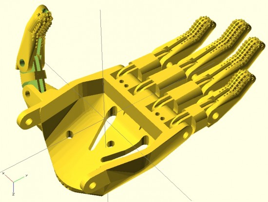
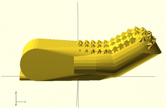
Here you can see the fingers placed appropriately with the palm. I’ve used the same “finger” designs to add a thumb.
For right now, this is just to demonstrate the progress so far. Theoretically, the only thing left to do is crank out an appropriate gauntlet to bring the entire design together. In reality, there’s still a fair amount of work to do. The design for the prosthetic palms was… not elegant. Also, I want to create a separate (but very similar) design for the thumb.1 It is possible that if I improved the finger designs, I might be able to get away without designing a separate thumb.
In the meantime, I think it looks good and would probably be functional as-is.
Onwards and upwards!
Default Series Title
I feel like the thumb should be stubbier, so I’ll go back and adjust the designs accordingly. [↩]
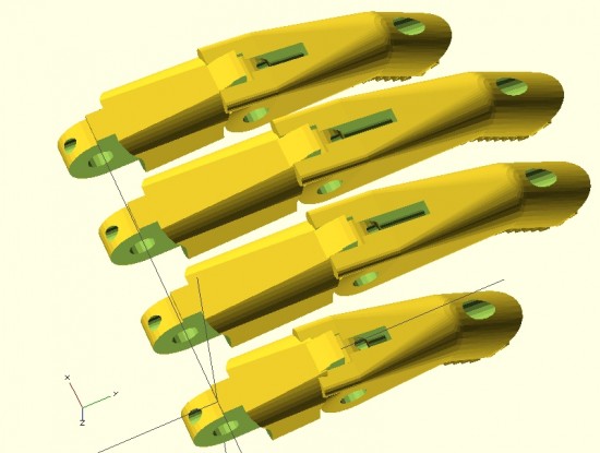
Parametric fingers – different lengths, same scale, with no distortion to hardware
I’m not ashamed to admit it – I’m proud of these parametric designs like few of my other designs. I’ve worked to make this design as customizable and organic as possible. The two modules that define each finger can be customized in two important ways – they can be lengthened1 as well as scaled up or down – without any distortion or change in the size of the holes for the hardware, elastic cords, or tension cords.
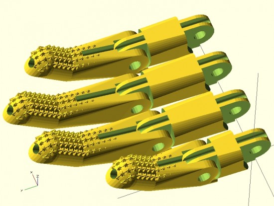
Parametric fingers – with grippy bits
Being able to lengthen2 the finger segments is important because it allows the user to create fingers of different lengths, as normal fingers are of different lengths, all without having to actually scale the fingers to different sizes and without causing a change in each finger’s diameter.
As I’ve discussed in earlier posts, being able to scale the parts up and down without distortion to the hardware holes is important because it allows users to use standard hardware throughout different designs.
For now, it’s back to work on the parametric palm to ensure a proper fit with these parts.
This post is intended as a set of “guidelines” to creating a parametric design in OpenSCAD.
Last Sunday afternoon was spent working out a parametric design for printable prosthetic fingers. Using the OpenSCAD function “hull” it’s relatively easy to crank out a nifty organic appearing design. Admittedly, you have to have a working knowledge the basic union/difference/intersection function first. However, once you do it’s really quite easy.
The feature of the design I’m most proud of is the “nail” part of the finger tip. I designed the “nail” by using the OpenSCAD function “intersection()” on two cylinders. The little “nubs”1 consist of a small cube, rotated so a corner is pointed straight up combined, with an identically situated cube rotated slightly.
When I’m designing something to be parametric, I usually don’t really start out designing it that way. I first strive to create a form in OpenSCAD that resembles closely the thing I wish to design. Then, I poke through the design code looking for those elements that are related to the design aspects I’m interested in changing based on parameters. Once located, I replace those parts of the design code with variables that can be specified when the module is called. I realize this is kind of a “high level” description of my design process for parametric things, but it’s still the best description.
Since last Sunday I’ve really done a lot with the design. Some simplifying and a lot of improvements. In the next post I’ll go over these features. I’m really excited to show these off. :)
Above is my first attempt at designing a “solid” finger for the Cyborg Beast DIY printable prosthetic in OpenSCAD.1 The reason this is a “solid” finger is that I haven’t subtracted out any material to allow this partial finger to connect with anything else.
The problem with scaling (up or down) any design that requires fasteners and hardware is that when you do, the holes for the hardware are similarly scaled. This leads to more post-printing work drilling holes to widen them or to find larger fasteners that won’t rattle around in too-large holes.
Thus, if the hardware consists of 3mm screws, the holes for the hardware should be 3mm no matter how much the parts are scaled up or down. To make matters more interesting, not all holes in the model should be excepted from scaling. The above finger tip has a plastic end that is supposed to fit into a mid-finger piece – and those parts should be scaled up or down according to the size of the overall hand. Thus, some voids should be scaled2 and others not at all.3
I’m rather happy with how this finger has turned out so far. It has most of what I understand to be the essential features of the Cyborg Beast fingertips, including little nubs along the finger pad to allow for gripping. I intend to make this an option, in case a user would rather use something like Plasti-Dip to make grippy finger pads, rather than relying on printed plastic bumps.
However, converting a decent design into a parametric design requires a little more work. The way I go about designing a parametric model is to first design one instance of the thing, in this case the finger tip. My next step is to poke through the OpenSCAD code to locate those aspects parts that contribute to the models’ essential features – length of the finger tip, for instance. Once I’ve found these bits, I then try to modify them so that I can insert different variables and arrive at sane variations on the model.
WORKED: The fit. I’m really happy with how the pen holder went together. It’s always very satisfying to print a part you just designed and have it “just fit.” With the zip tie holding the micro servo in place, neither the micro servo tab nor the zip tie protrude beyond the flat surface of the pen holder. The groves for the rubber band to hold the pen in place work very well. The pen doesn’t move side-to-side, get pushed back into the holder, and it is very easy to reposition the pen or change pens entirely. While it’s not as elegant as, say, a metal spring, it works very well and doesn’t require a bunch of moving parts.
WORKED: The amount and placement weight. I hot glued a AA battery to either side of the pen holder, as close to the center as I could manage around the hole for the pen. This weight seemed to work perfectly. There was enough weight that the cords hung in straight lines, but not so much that it seemed to cause a strain on the motors. The placement of the weights seemed to work well as there was no noticeable pendulum swinging of the pen holder, despite me running the robot at about three times it’s usual top motor speed and about twice it’s normal acceleration.1
WORKED: The multiple points of cord attachment. Having a row of holes for connecting the cords at different points along the top central edge of the pen holder worked out great. To test the balance all I did was stick a small paperclip through a hole. If the holder balanced with the flat edge upright and vertical, that’s the point I needed. It was easy to find the balance point and easy to connect the cords.
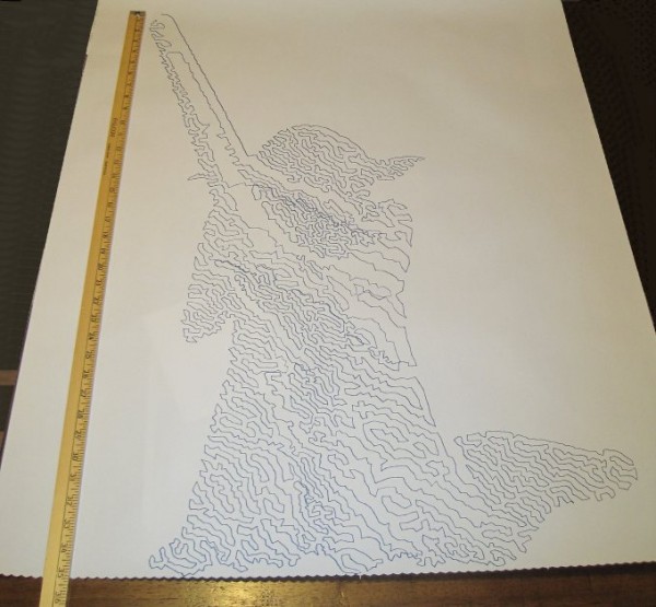
WORKED: The single point of cord attachment. When I was using a crappy cardboard pen holder with cord attachment points very far apart, the entire pen holder would tip to one side or another when it got close to that side. This caused a bubble-like distortion effect towards the edges of the drawing. While this could be a cool effect to intentionally inflict on a drawing, it’s not what I was going for with that crappy cardboard design. Having the two cords meet at exactly the same point worked out incredibly well. Even when the robot was drawing the top left corner of Yoda’s lightsaber, the pen holder was always perfectly vertical.
WORKED: Shape of pen holder flat side. The pen holder I’ve designed is roughly teardrop shaped, with a flat top. My thought with giving it a “flat top” was that it wouldn’t potentially develop a central raised point (between the circular top edge of the pen holder and the device I was using for the pen lift) when I was doing a pen lift. I figured that if I was using a “flat top” it was possible for the pen holder to be balanced on the edge of the flat top and the point of the servo arm – essentially turning my full contact pen holder into a three point contact pen holder with the servo arm as one of the points.
DIDN’T WORK: Motor skipping? There is a large section in the middle of the drawing of Yoda, pictured above, that looks like it was shifted downwards slightly. This could have been because I was fussing a little with the robot while it was working. It could also have been because I was running the robot pretty fast (motor speed of 1600 when the normal is 600), because I had increased the acceleration (400 instead of the default 800), because I had the pots turned down too low (maybe, but the current settings have worked reasonably well for other drawings), because the pen holder was too heavy and causing too much strain on the motor (very unlikely since this holder is lighter than the cardboard abomination I was using) or some combination thereof. My guess is that I probably need to increase the pots when I increase the speed. It’s really unlikely that the pen holder itself was to blame for these missteps.2
DIDN’T WORK: The pen lift. I haven’t drawn anything with a pen lift yet – but I did test the pen lift last night after Yoda was done. I noticed a few minor problems with the pen lift – but nothing to indicate I was on a completely wrong track.
The first problem is that I glued the two batteries slightly too close to the clearance area for the micro servo arm. This is why the next version will include a holder for the AA batteries – to ensure they don’t get in the way.
Second, even when fully extended the servo arm didn’t push out far enough to cause the pen tip to lift off the surface of the paper. This could be solved by either making sure the pen tip is positioned slightly farther back, extending the servo arm, or creating a servo arm powered cam, similar to Dan Royer’s Makeangelo (check out the video at about 4:35 for a view of the cam in action).
Third, my concern is that since the micro servo is mounted in such a way that the servo arm sweeps from right to left, it could cause a similar sweeping motion to be applied to the pen tip – assuming I work out the pen tip depth issues. It’s possible that sweeping the arm upwards or downwards might minimize this effect. I just have no idea whether this is a valid concern or not – the servo arm might move so quickly that it’s not a real concern.
Also, while not an actual issue, the servo motor cable applies a bit of weight to the pen holder. This will require me to reposition the cord attachment points – and may require me to add extra weights to the pen holder itself.
Once I change the pen position and maybe use a larger servo arm, I’ll try a vector drawing which requires pen lifts and re-evaluate this design. Overall, this design has basically worked beautifully. I’m looking forward to experimenting with some new variations on the design to see if I can eliminate the few remaining issues.
Default Series Title
I’ll pretend I was doing this for a system stress-test, but really I was impatient to get a big giant Yoda drawing [↩]
I admit it, I’m prone to verbosity. I wrote 2200 words just discussing the kinds of pen holders other people have used and another 2300 words talking about what I consider to be ideal qualities in a pen holder.1 In some ways, the pen holder is possibly the least important part of the entire robot. When you can use something like a binder clip or cardboard, hot glue, and dead batteries to create really amazing drawings, it’s almost a waste to spend any time thinking about what makes an idea way to hold a pen. However, since I’ve got the rest of the robot looking and working just like I always wanted, I’ve latched onto this last part as something I would like to optimize.
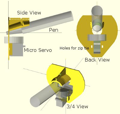
Above is an OpenSCAD rendering of a pen holder I’m getting ready to try out. As I type these words, my Replicator is a little over 50% done printing the pen holder. Before my threemostrecent posts discussing pen holders I had been working on an overly complicated, multi-part, pen holder. It consisted of several pieces that would be printed simultaneously, several spots for captive nuts – the features went on and on. Don’t get me wrong – a pen holder like that might be genuinely great – but I’m not sure that level of complexity is necessary or in any way worth the design time.
The design pictured above meets several of my criteria for an ideal pen holder. For your consideration, I submit the following features, design choices, and design elements:
Just one very lightweight part. This printed part would require only a rubber band to keep the pen in place and, if you’re using a micro servo, a single zip tie to keep that in place. At the moment the design doesn’t include a space for weights. Once the part is done printing, I’m going to put it together with the micro servo and pen and see how it hangs. If it looks okay, I’ll hot glue some batteries to it in various spots. If that works well, I’ve already got a variation on this design which includes some printed tabs for adding dead batteries for weight. The part itself uses very little plastic and prints fairly quickly.
“Full contact” stabilizer. In a prior post I discussed the several types of pen holders and how they can have a single point of contact with the drawing surface, three points of contact, or “full contact.” While the Polargraph style pen holders use a blank CD (120mm in diameter), the above just uses a mostly round shape 80mm across. I don’t know if this is wide enough or not, but this is a first draft.
Pen held at angle. Felt pens and markers don’t really require they be held at an angle, but I can’t imagine it would hurt. Well, I suppose they could have too much ink come through – but I could just run the robot a little faster. There’s no science behind my choice of the pen tilt at a 15 degree angle, it just seemed like a reasonable number. Since it’s a parameter in the OpenSCAD file, I can easily go back and change it if this is just a terrible choice.
Cord attachment points #3, the “Single cord convergence point, not at the pen tip.” This pen holder is designed to allow the cords to essentially meet at one specific point – namely one of the tiny holes in a row along the top edge of the pen holder. These are most visible in the top left of the above picture.
Centering point viewer. Since the cord convergence point is centered on one of those tiny holes, the user of this pen holder can look through a tiny hole the the flat surface of the pen holder to make sure the pen holder is properly centered and homed.
Multiple points of cord attachment. Depending upon pen type, pen weight, and pen holder weight and distribution I could imagine there might be different optimal points of cord attachment. The top edge of the pen holder has a series of holes through which the cord could be fed. The way to attach the cords would be to create a small loop in the end of the cord, feed it through one of the holes and then hook it onto the protuberance at the end of the row of holes. (You might have to look at the top left picture a bit to notice this bit). The other cord would be fed through the same hole – just on the other side and hook onto the same protuberance. This setup was inspired by Dan Royer’s multiple point of attachment set up and the AS220 labs “clip stabilizer.”
Pen held securely in place and depth. A rubber band should do the job of keeping the pen in place nicely. I added a groove to the top edge of the holder where the rubber band can rest. I can’t imagine needing a cord attachment point as far back as the groove near the pen holding cylinder, so I fully expect the last four or five holes can be eliminated, which means I can use the groove around the pen holding cylinder as it was originally designed – to serve as the resting point for the rubber band.
Multiple pen diameters/pen lengths. Although this holder was designed for a pen with a maximum radius of 20mm, it could probably accommodate up to 25-30mm. All but one of the pens in my house would fall in the sub-20mm-diameter category. The reason for having the rubber band point so far back along the pen is that most pens are tapered towards the marker tip, which means you can’t really hold the pen any closer than 20-30mm back from the tip. The holder is designed to hold the pen 30mm back from the pen tip, which is enough to accommodate all but the absolute largest marker.
Holder for micro servo. The holder was specifically designed for my micro servo. Once the micro servo is inserted (in the orientation shown by the shadowy looking micro servo in the images above) one of the tabs for the micro servo sits completely flush with the flat side of the pen holder. There are holes on either side of the micro servo through which a zip tie can be fed. There’s even just enough clearance so that the zip tie itself doesn’t protrude past the flat surface of the pen holder.
Clearance for the widest servo arm. I know many others have designed much better mechanisms for having a micro servo perform a drawing robot pen lift. Since this is literally my very first attempt to incorporate a micro servo into one of my drawing robot projects, I figured I would just use a bare-bones approach and have the servo’s arm directly push the pen holder off the drawing surface. I’m positive there are more optimal ways to do this but again, this is a first draft.
I’ve uploaded the files to Thingiverse, to be followed by my janky OpenSCAD file. It started off totally parametric and then as I got close to finishing it, I just started entering in numbers that would make it work. I’ll go back and improve it, but for now I’ll share what I’ve got.
Default Series Title
I haven’t even started blathering on about different kinds of pens! [↩]