Remounted extruder controller board

Tony’s recent comment to my post about my alternate extruder controller board mount really deserves its own post.  Tony’s comment was:

That’s a pretty logical place for it. Other than needing some more wiring, I wonder why they didn’t design it that way? I wonder if it might introduce some EMI noise?

I’m about 95% sure I know why they designed the extruder mount on the extruder itself rather than the side of the ‘bot.  As designed the entire extruder is completely modular.  You could swap in a brand new extruder assembly in about 30 seconds (four bolts, one ethernet cable).  Heck, if you had a second Z stage and extruder you could probably swap in a new extruder in 15 seconds (one ethernet cable, swap Z stage).  They’ve said from the beginning they wanted their system to be totally modular and hackable – and that it is.

I haven’t noticed any symptoms of EMI noise on my prints.  In fact, I’m getting some really great prints with my current Skienforge settings.  I have a little blobbing and stringing – but I suspect that could be fixed with some attention to oozebane etc.

There are a few really great things about my setup:

  1. More modularity. A totally new extruder (let’s say dedicated to PLA or a different color ABS) would not require a second extruder board.  This means with a printstruder and printed dinos (I’m still refining those designs) you could have a totally modular extruder for about $65 worth of hardware rather than $175 ($125 plastruder kit + $50 extruder controller board).
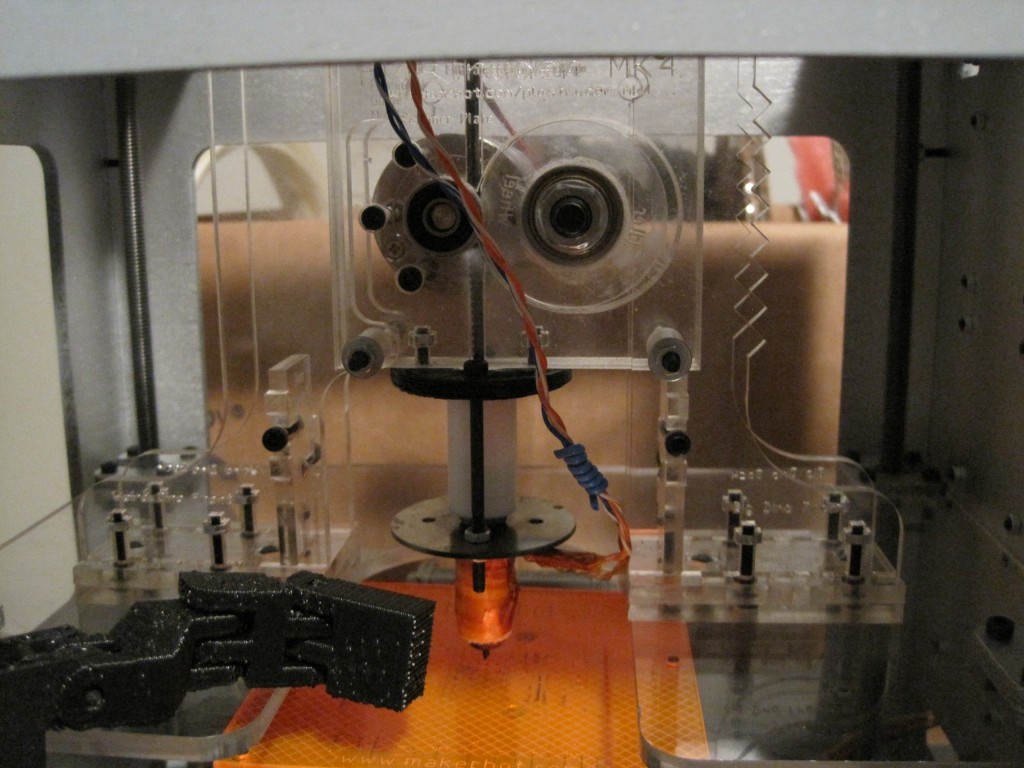
  2. Visibility. I can easily see what’s going inside the extruder and whether the idler wheel is moving – without lines on the idler wheel.
  3. Less work. It’s one less thing to take off the extruder when I need to do any kind of work on the extruder.  It’s not much time, but it is still a benefit.
  4. Ergonomics. My ‘bot is sitting on a surface about 5 feet off the ground.  Having the motherboard rotated 90 degrees counter clockwise allows me to front-load the SD card.  This is easier for me because of the surface height, but I also had to do it because otherwise the side mounted extruder board would have blocked the SD card slot.  Frankly, I would rotate the motherboard even if the extruder isn’t side-mounted.
  5. Centrality. This keeps all of the electronics all in one spot and makes inter-board cabling slightly easier. 1
  6. Less movement. I doubt moving the extruder board around on the Z stage would ever cause a problem – but it certainly won’t when it is side-mounted.

However, this setup isn’t perfect:

  1. Less modularity. One could argue that having the extruder board side-mounted decreases the modularity of the system.
    1. Counterpoint: That said, if you already have an entire second extruder complete with extruder board, there’s nothing stopping you from swapping it in as easily.
  2. More wires. I now have six wires2 running to the extruder board.  Disconnecting/reconnecting six wires is more work than disconnecting/reconnecting one ethernet cable.
    1. Counterpoint: In just about any circumstance where you are disassembling your extruder you’re going to need to disconnect those six wires anyhow.
    2. Counterpoint: I picked up a six pin male/female connecter set the other day.  Once I clip the wires I can again have a plug-n-play extruder without needing to fiddle with screw based connectors or with the extruder board in the way.
  3. More maintenance. Those same six wires need to be maintained/wrangled instead of one ethernet cable.
    1. Counterpoint: As you can see from the pictures I’m using the little blue twist-ties that came with the ethernet cables to essentially bundle the wires together.  I just wind the twist tie around the bundle and compress it to form a tight coil.  Works really well with several of these placed at intervals.  Clean and still flexible.
  4. Shielding. There is less shielding on the six thing wires versus one large ethernet cable.
    1. Counterpoint: This has not been an issue for me.
  5. EMI noise. I’ve never had problems which I would attribute to EMI noise from wiring, but I suppose it is possible.
  6. More work. It is slightly more work to put the extra holes in the side of the bot to allow the motherboard to be mounted 90 degrees counter-clockwise and mount the extruder board on the side.
    1. Counterpoint: Perhaps 5 minutes of work total?
  7. Z stage blockage. My extruder board is attached by only three bolts because one of them interfered with the Z stage.
    1. Counterpoint: This just isn’t that much of an issue, especially with the extruder board remaining stationary.

Overall, I find the benefits far outweigh any problems that side-mounting the extruder might cause.

  1. But, as you can see from the prior post, not much neater. []
  2. Two each for the thermistor, nichrome, and extruder motor. []

Alternate alternate extruder controller mounting

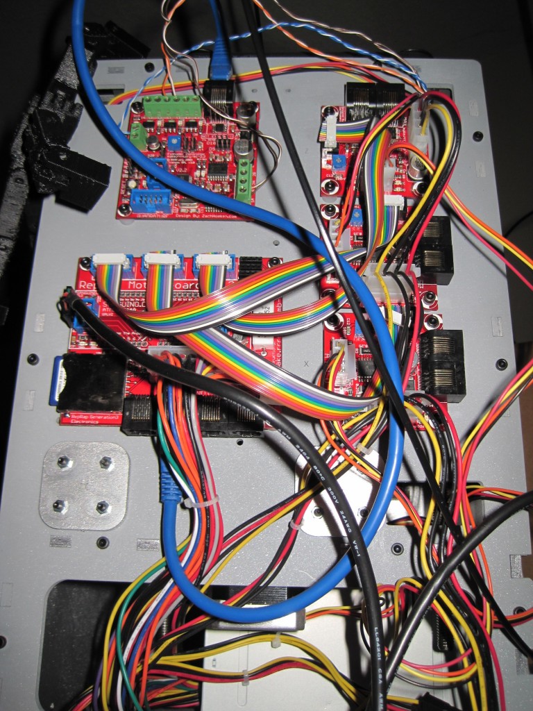
Tony Buser’s post about his Alternative Extruder Controller Mounting reminded me that I’ve been meaning to show a better picture of my own setup.  I had blogged about it earlier, but not shown a good picture.

Side mounted extruder board, rotated motherboard

Side mounted extruder board, rotated motherboard

Here you can see where I’ve mounted the extruder board at the top left and how I’ve rotated the motherboard 90 degrees counter clockwise.  This gives me better access to the SD card slot.   If you don’t rotate the motherboard, the SD card slot is blocked by the extruder board.

Totally clear plastruder

Totally clear plastruder

Here you can see Leonardo Robot’s arm and how I’ve run the wires from the extruder motor and heater up to the board.

How to diagnose and fix a burned out thermistor

Unfortunately, Bender just stopped working.  As I was keeping the nozzle warm while I was working on a new model, I looked up to see a flash of fire/spark shoot out from the nozzle area, ricochet off the build platform, and disappear.  Looking at the RepG control panel I discovered that I wasn’t getting any readings from the thermistor.  Not good.

The RepG control panel showed 0.0 as the temperature, so I shut the plastruder down, not wanting the heater to burn out of control.  I restarted Bender and RepG – but I discovered that while I could control all three axes very slugishly, I could not move the extruder motor or detect temperature.  I’m guess I couldn’t have increased the temperature either, but I didn’t want to try it since I couldn’t monitor the temperature.  That about covers the symptoms.

In order to diagnose the problem I tried to isolate the various parts.  I pulled all of the wires out of the extruder board.  Then, while the wires were still out I tested the nichrome for resistance – still around 6ohms.  Then I tested the thermistor – no connectivity.  Again, not good.  I tested the  motor for continuity, and it was fine.  Since the nichrome and motor seemed fine, that left the thermistor and extruder board.  I popped a random resistor into the thermistor ports, but still couldn’t get a reading on it.  Unfortunately, after several resets of the motherboard and extruder board, I still couldn’t get the motor to move or a reading from the thermistor.  Also, I was getting an error message that the Payload was not big enough.

Rick Pollack of MakerGear suggested on the MakerBot Operators group that I reflash the extruder firmware.  After several failed attempts, I finally figured out how to flash my extruder firmware from the Arduino environment by holding down the extruder reset button.  This got rid of the payload error message as well as the avrdude errors and let me reflash the extruder.

I pulled the entire extruder apart and did a little maintenance.  I flossed the extruder pulley teeth, pulled all the stray bits of plastic out of the idler pulley wheel area, removed the old thermistor, unwrapped the nichrome (which was wound down and then doubled over itself as the original pictures in the wiki suggested) and rewrapped the nichrome (a single layer from the nozzle up the barrel following closely in the threads to make good contact everywhere) as suggested by several people in the MakerBot operators group.  I then tested the nichrome again once it had been taped down for the proper resistance, check.

Once I pulled the thermistor out of the heater assembly, I tested the thermistor at its own leads, rather than at the wires soldered to it (in case the thermistor had come apart from the wires).  Still nothing.  I plugged a random resistor into the thermistor ports and was now able to get a reading off the extruder (as well as move the extruder motor). Concluding my problem was the thermistor, I forged ahead with a plan to replace it.

Luckily, I had placed an order for some PLA and nearly every single part needed for a secondary extruder (or what would be needed to fix a broken extruder) including a new thermistor.  If you haven’t picked up backup parts, I highly recommend it.

I clipped the old thermistor off the wires, pulled out the new thermistor and taped it to a white piece of paper immediately, putting the tape across the leads just below the bead.  I then bent the leads upwards, tinned them, soldered them to the wires, taped down the wires, pulled up the original piece of tape, and then sandwiched the thermistor in tape as per the instructions.  I then plugged the heater, the motor, and the thermistor back into the extruder board – and was able to get a temperature reading, apply a little heat to the barrel, and move the extruder motor.  I also noticed that this removed the sluggishness from the 3 axes stepper motors.

With the heater, motor, and thermistor working separately I put everything back together and reassembled the plastruder, plugged it back into the board and tested it again – readings, heat, and extruder motor working.  I then popped it back into the dinos, did a test extrusion, and starting printing again.

“Rock on completely with some brand new components”

More calibration

Calibration is proving to be a relatively slow process. As you can see from my prior post, my prints are drifting towards the back of the MakerBot. This appears to be due to either improper tension, the power being set too low for the Y stepper motor, and/or the Y axis rods not being smooth/oiled/straight enough. Given that the first few layers are spot on, I suspect it is a stepper board power issue. The Y axis motor is easily the first quietest of the three axes. As the X axis motor is the nosiest, I could probably dial it back without an effect on performance.

To do for tonight:

  1. In the hopes of diminishing the Y axis drift problem
    1. Oil the Y (and X and Z) axis rods
    2. Check the Y (and X) axis slides
    3. Dial up the Y axis power by turning the potentiometer on the Y axis stepper board clockwise
  2. In the hopes of diminishing operational noise
    1. Dial down the X axis motor slightly
    2. Dial down the Z axis motor slightly

My first hack

Seeing as how I already had the heater in pieces, I figured it couldn’t really cause that much harm to move the plastruder board.  I totally get why the MakerBot guys put the board on the extruder – that way all you had to do was swap out an extruder and you can roll with a totally new print head.

I don’t really intend to do printing beyond single color plastic.  This may very well change if we see a support material extruder being offered.  But for the foreseeable future, I am really looking forward to printing away with my giant coil of black ABS.

That said, I’m not attached to the idea of having totally modular heads. 1  On the right side of the MakerBot there’s a really large area above the motherboard and to the left of the three stepper motor boards.  The only things preventing the plastruder board from being mounted right there are (1) the motor wires are too short and (2) four holes in the body.

I had dissected a piece of ethernet cable for the wires running to the nichrome wire and thermistor, so I still had four wires left.  I used another two and a bit of solder to extend the wires to the extruder motor.

Sometimes when I need to drill a small hole through soft or thin material I don’t even bother with the drill.  I used a small drill bit with a rubber band wrapped around the non-drill-bitty-end to give it a grip and rotated it into the right panel of my MakerBot.  Bolt it on and…

Presto!  Now I can see all the way through the plastruder.  :)

  1. Sorry about the pun. []

With a little help from my friends

Thanks to the kind folks at the MakerBot Operators Group I’ve been diagnosing what’s going on with my Y axis stepper board and plastruder.

1. Y Axis Stepper Board

No matter what I was doing I couldn’t get the Y axis stepper board to respond to any commands.  Also, the power light on the board would light up as the MakerBot powered on – however it would immediately dim to nothing.  I swapped out every single cable, the motor, and it was always the Y axis board!  Finally, I completely pulled the board off the ‘bot, pulled every cable, and started adding the cables back one by one… and it worked!

I was concerned with why it wasn’t working, but happy it was working.  So, I bolted it back on, connected the wires… and it didn’t work any more!  What went wrong?  It was one of the opto-endstop cables.  I discovered that when I connected the front opto-endstop cable it would kill the power to the Y-axis board – or any other board!

The Y-axis three prong cable is easy to insert upside down.  And that’s what I was doing – because it fit better in that orientation.  Well, flip it upside down and rock on!

2. Plastruder / Extruder Temperature 0.0

Now that I could manipulate the 3 axes, I tried to use the plastruder.  I noticed that even at room temperature the thermistor was reading 0.0.  Also, the heater was smoking a little, I could smell something burning faintly, and the extruder was oozing something clear and sticky.  Not ideal.

With a lot of help from the guys at the MakerBot Operators Group I attempted to diagnose the problem.  Here’s what I tried:

  • Testing the resistance of both the nichrome and thermistor while both were still plugged into the plastruder board.  Both seemed okay – but I still could not get a reading from the thermistor.
  • One suggestion was to plug a random resistor into the thermistor ports to see whether the board and software was receiving information.  Being a complete novice and having zero spare parts around, I actually had to make a trip to the local electronics store for a single resistor. 1  Once plugged in the resistor (a quarter watt 10k) must have been resisting stuff because the board interpreted it as a temperature.  Thus, the board and software are probably fine. 2
  • Thus, I disconnected the heater wires and thermistor wires and tested them away from the board.  I really should have done this in the first place.  It would have told me that the thermistor was either burned out or no longer connected to the wires.
  • Taking the heater apart was almost painful.  The ceramic tape was a little scorched, parts of the kapton tape closest to the print head were actually burned to a blackened crisp and flaking off.  It was just not pretty.
  • The nichrome seemed to still be intact and giving the proper resistance, but the thermistor was not showing connectivity.  I was pretty bummed that I may have cooked it.  But, when I started to peel that tape away, I tried to test the resistor leads – which did show the proper resistance!  I checked the connections between the thermistor leads and the solder and discovered that one of the leads had lost its connection with the solder/wire.
  • I then tried to resolder the wire to the thermistor and then rewrap it into the kapton tape and tried its resistance again – and got a proper reading.   Then I taped it to the extruder head, to see if I could get a heat reading off of it – and I did!
  • This time, I went VERY slowly.  I tested the heater/extruder head completely apart from the printing assembly with the thermistor taped to it – I could heat and read the temperature.  I then wrapped it in tape, tried again, success again.  Then I wrapped it back in the ceramic tape, heated/read again with success.  Then I put the assembly back on the plastruder, heated/read again.
  • Now, a decision I made that I may very well regret later was to leave the nichrome wrapped as it was and not pull it all off and rewrap it.  The testing showed it was intact, it was still in its fiberglass insulation, and I had done a pretty good job of wrapping it in the first place.  In rewrapping the heater I took out as much of the burned kapton tape as I could and then wrapped it back up.
  1. I picked up a lot of other stuff while there, but this a single resistor was the actual purpose for the trip. []
  2. Thanks Rick Pollack! []

Things I learned while soldering opto-endstops

The opto-endstops marked the very first parts I had to solder for this MakerBot.  Not having soldering anything more complicated than two wires together, this was an adventure and learning experience.  Here’s what I learned today:

  • The 3-pin connectors used for two of the opto-endstops (on the Y-axis stage) are in the Generation 3 MakerBot Electronics Kit (Mostly Assembled) with some of the other connector bits.  I was a little confused about this for a while.
  • It helps to lay out all the little bits in an organized fashion beforehand.
  • Keep a long thin rigid stick handy for bending delicate leads into the circuit board holes.
  • Although I read the RepRap electronics fabrication guide and found it helpful, I still felt a little lost.  I found the most effective way to solder the parts in was to:
    • Get the soldering iron good and hot
    • Put the leads through the holes
    • Bend the leads a little so that they stayed in place
    • Flipped the board over so the leads were sticking up
    • Touched the solder to where I wanted the joint
    • Gently stroked the solder with the soldering iron tip towards the joint
    • This process seemed to create a pretty good joint
  • You’re going to burn a finger at some point, accept it.1
  • This almost goes without saying, but go slowly.
  • Check and double check the orientation and placements.
  • I found it helpful to take a large sheet of aluminum foil and shape it into a tray.  This helped contain the parts I was working on and was a good way to catch the flying leads that I clipped off.
  1. I burned two. []