A friend of mine pointed me in the direction of some ESP32 board tutorials over at MsRaynsford.co.uk.1 You know it’s a fast moving area when a post that’s less than a month old already has a dead link. :) Rather than re-creating all the tutorials that are already out there, I’m going to just jot down my notes and links as a short of “quick start guide to quick start guides.”
- ESP Boards
- There’s several different “flavors” of ESP WiFi tech, however it seems as if they all break down into one of three different categories.
- Bare ESP WiFi module. These require a bit of effort to make work since the bare module requires the pins to be broken out to be made useful.
- ESP WiFi breakout boards. This type of board, which has 8 pins broken out, requires a programmer. Since these 8 pins are arranged in a 2×4 pattern, they can’t be used directly in a breadboard.
- ESP WiFi development boards. These board seem to have lots of pins broken out and typically a USB connector. Since these boards have more features (voltage regulators, compatibility with other boards’ form factors, USB communication built-in), they’re going to be more expensive. There’s the Adafruit Huzzah, the Sparkfun ESP Thing, and then something called the ESP Wemos D1.
- There are several different ESP modules and boards which have varying amounts of space from 512kb to 4MB and varying amounts of pins from 2 to 24 pins. These modules all tend to have different names (ESP-01, ESP-07, etc, etc) but are all known as ESP8266.
- The ESP modules require 3.3v, so a 5.0v USB or other source will fry them. Plan accordingly. Some development boards have voltage regulators on them to adjust the power going to the module.
- There’s several different “flavors” of ESP WiFi tech, however it seems as if they all break down into one of three different categories.
- Correct Board Manager URL for ESP boards
- An overwhelming amount of information for ESP boards
- Ordering Boards
- I’m ordering several boards off of Aliexpress. I’m getting a few Wemos D1 boards, since they’ll be easy to prototype with2 , and a few ESP-01 breakout boards and a single programmer to toss into a project. Then again, at <$3 a piece for the Wemos boards and <$2 a piece for the ESP breakouts, it doesn’t make a ton of sense to stretch to put the ESP-01’s into a project. My thinking is that most any project I build will only use a pin or two and not be too terribly complicated anyhow, so that once it’s been prototyped I can just burn it into the ESP-01’s and permanently install it into a project.
- I’m not exactly sure which what WiFi enabled things I’d like to build yet. 3 Here are some ideas:
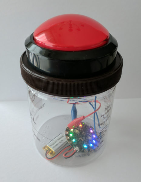
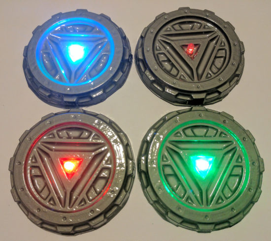
- A pair of tap lights that are connected over the internet. I’d tap one before I left work, it would flash a color to let me know it sent a message, and the other one at home would light up to let my fam know I was on the way. I guess it’s similar in theory to this.
- A button to call an Uber or Lyft.
- A button that will email or call my cell in 2-5 minutes from the time I press the button. Useful when I know someone who stepped into my office isn’t good at taking a hint. Or when I need to get off a conference call.
- A button that can be used to log simple events. Might be useful at work in a variety of ways.
- A button that will automatically start a print job on my WiFi enabled 3D printer.