I suspect most makers do something very similar to this, whether they realize it or not. My own variation on this method is to create an outline of what I want to learn with each feature I want to include, do some preliminary internet research, add links to resources to the outline, read, drill down on topics, ask questions, LRR.1
Goals
Keyboard
Media knob, media buttons, with a layer shift (ideally, through triple click)
Another layer with function buttons for data entry for work
Sweet RGB underlights, perhaps different lights for working and for media, perhaps different lights with keypresses
Switching “layers” on a QMK keyboard means you can store entirely different layouts of keys and/or key assignments in one keyboard – basically giving you the functionality of multiple keyboards in a single device
Sometimes I’ll document stuff in a notebook, but when it’s something I know will take some time to learn and probably require code and other digital resources, I like to type them up in blog posts. It feels therapeutic, getting all this stuff written down. I think of it as closing mental browser tabs. Also, by adding links into a post, I can actually close real browser tabs, which is a distinct side benefit.
Once I started looking, I found a lot of options for a custom keyboard. In fact, I started seeing them everywhere.1 I found these offered as some combination of “media,” “macro,” “button,” “board,” “keypad,” and “keyboard.” I’m offering this list in no particular order – other than how I noticed each one.
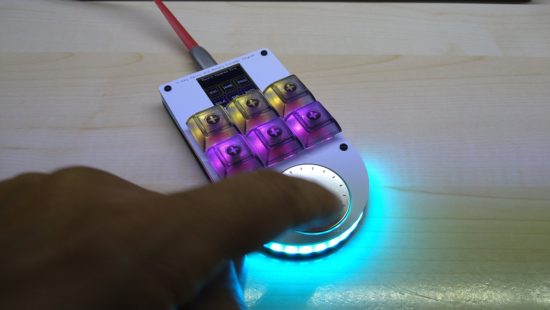
I found @iHayri1‘s keyboard in HackSpace magazine, issue #37, page 101. If you don’t happen to have it lying around – no problem! This magazine published by the Raspberry Pi Foundation gives away their digital version! While on the pricier end of the keyboards, it’s got a lot of interesting features. Six buttons, a media dial, an RGB LED under each key, a series of LED’s at the base of the keypad, and an LCD screen displaying each key’s current function. I would have ordered this one, except it’s been out of stock for a little while. :)
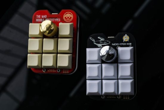
I found the NoodlePad by @TheMadNoodle on Etsy after searching for media keypads. This is another beautifully designed board – eight buttons, knurled metal knob, mounted onto a shaped board and thick lasercut acrylic plate. This was the first board I saw referencing “QMK” firmware. This board is also offered in a “semi-assembled” state where the buyer supplies their own switches and keycaps. If you’re going to fall down a rabbit hole on mechanical keyboards, the switches may be what get you. The ordering options also offer “Cherry Red,” “Cherry Blue,” “Cherry Brown,” and “Cherry Black” switches. At first I thought this referred only to the color of the switch underneath the keycap. As it turns out, each color matches the little bit of plastic connecting into the keycap which in turn is associated with a different set of mechanical features for that particular kind of switch. Maybe you want a key with more bounce, requires more force, or a more gentle touch. That you can order your keypad with the exact keys you need says a lot about this maker and their product.
I happened to catch @travis_the_makr showing off a prototype “BYO Keyboard” on Adafruit’s Show and Tell. I should probably feel a little bad for hassling Travis to sell me one of these board immediately after his appearance on the show. Intended as both a way to get started with soldering and programming as well as an actually useful final project. I kinda love the project is powered by an Adafruit Itsy Bitsy M0 so you can use either Arduino or CircuitPython. I note QMK firmware support is a stretch goal. :) Don’t let this bare bones DIY kit without LED’s, knobs, and displays fool you. If, like me, you’re only now embarking on your mechanical keypad journey and don’t have a drawer full of Cherry MX switches and keycaps, this is an excellent and affordable starting point. Suffice it to say, I immediately pledged the Kickstarter and am really looking forward to playing with this project.
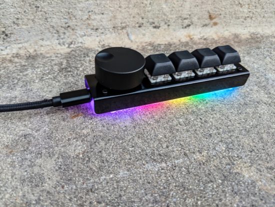
Of all the various keypads I’ve looked at, this was the very first one I ordered. I opted for the version with the black steel case, wonderfully heavy metal knob, and asked the owner for some variation in the keycaps. Craig shipped the keypad immediately and it arrived well packed in bubble wrap, only requiring that I pop in my choice of keycaps and apply the included sticky rubber feet.2 This keypad rocks four Cherry MX switches, a big hefty knurled metal knob, six RGB LED’s which glow through the lasercut acrylic base plate. My configuration (with the metal case) was $62, including shipping. While this is the only keypad I’ve actually used so far, it’s going to hard to top.
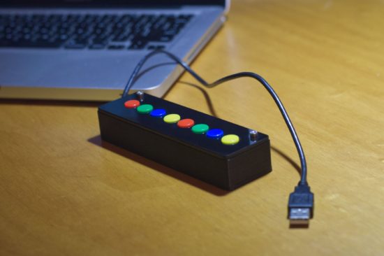
Once I started tweeting about picking out some keypads, my buddy Pete told me about the “8K Controller” by 2XLNetworks. This keypad has no LED’s, no metal knobs, no LCD displays – but it doesn’t need any of that. It comes with a built-in USB cable, you can order it with pre-programmed with custom button assignments at no extra cost, reprogram it if you like, and it unlike a hipster clicky-clacky Cherry MX switch, it rocks arcade buttons. If you need a bulletproof box that can stand up to repeated abuse at the hands of the public (perhaps for a photobooth, art project, school installation?), this is be the keyboard for you.
Default Series Title
I’m reminded of the Baader–Meinhof phenomenon; after the first time you notice something, you notice it more everywhere [↩]
TLDR: I’m going to try some mechanical keyboards to help me work from home and blog about my experiences.
I’m fortunate that I’ve been able to work from home this pandemic. I’ve always made a special effort to make my work more “digital,” by scanning and organizing digital copies of important work documents. In many ways working from home hasn’t required too many changes to my overall workflow. My entire office and desk space shrunk to just a single laptop propped up on a plank of cardboard with some holes to help distribute heat. I have to be more disciplined about creating digital notes, since I can’t cover my work space in post-its and illegible scraps of paper. Two pairs of noise cancelling bluetooth headphones are are taking the place of four walls and a door to help me concentrate and communicate “I’m working” to the kids. 1 While I’ve gotten used to one medium sized laptop screen, in place of a dual monitor setup, the one thing that’s been extremely difficult is using a laptop keyboard instead of a full fledged keyboard.
Which brings me, dear reader, to the QMK or “quantum mechanical keyboards.” The QMK is a keyboard firmware2 that allows you to create very customized keyboards and keyboard layouts.
A while back I wrote a Chrome extension to help me with some work related data entry tasks. It works by intercepting some of the top row function keys, preventing their default actions, and replacing them with some macros. This setup probably slashed the number of required clicks and keystrokes by 75%. My fevered dream is for a custom keyboard which could cut this yet in half.
Now, if that keyboard also has some media controls and sweet RGB goodness, well, then, awesome. Of course, this means I can’t just go order a keyboard off a shelf. While there are plenty of neat custom and QMK keyboards, to really get the most out of a board, to get exactly what I need, I will need to roll up my sleeves and actually dive into the firmware itself.
Next up – which keyboards?!
Default Series Title
Why two pairs? I originally bought one for myself and one for my wife, but now I’m just using one while the other charges… [↩]
“Firmware” is nothing more than software built to run inside a piece of hardware [↩]
If you don’t know who EMSL are, you’re missing out. Evil Mad Scientist Laboratories is a small family owned DIY electronics business in the California Bay Area with a deep enduring commitment and support for open source software, open source hardware, educators, and Makers.
And they are genuinely good people. Their blog is an incredible resource for anyone from beginners in crafts and electronics to grizzled veteran engineers. There are free tutorials, resources, and tons of kits for every level. I’ve purchased several of their kits and cannot recommend their products highly enough for the material quality, comprehensive (and occasionally playful) instructional materials, and support – including a robust community and forum.1
Since our family is home an awful lot these days, we’re always looking ways to keep our kids curious, engaged, and occupied. Our next project is the EMSL “BristleBot.”2
Their write up and video tutorial will provide you with all the information you need to help build a very tiny zippy robot from things you probably have around the house. 3 There’s a lot to talk about with your kids here – from basic electrical connections, off-center motors, springiness of the bristles, to how the directions of bristles affect the robot’s travel.
A box of parts to make enough for a whole classroom might be about $50 (or less) if you could buy parts in bulk. But, if you only need a handful of BristleBots for your household, you could taking things apart for motors, old toothbrushes for bristles, common coin cell batteries for free/nearly free, maybe adding some matchbox car or marble run tracks for BristleBot trails or a cardboard box for a battle arena.
Still high off Maker Faire 20191 , I was also excited by the prospect of #CephalopodWeek on NPR’s ScienceFriday. Between cuttlefish, squid, and various octopuses (especially the “Opisthoteuthis Adorabilis“), there are a LOT of awesome little friends to consider making.
While trying to avoid work, I posted a sketches to Twitter.
This slideshow requires JavaScript.
Last week I started designing a few parts, drawing from some experience designing printable prosthetics for the E-nable project a few years ago. I was trying to build it out of what I had on hand, which did not include elastic cord. I thought a zip tie might provide enough “spring” and “give” to work.
This slideshow requires JavaScript.
I admit, this was a total mess. I suppose it is only fitting I use this meme featuring Dr. Zoidberg.
Thanks Dr. Z
Thanks to some kind encouragement from Odd_Jayy, I kept moving forward. Rather than focusing on the end of the tentacle, I got to work on the basics of the mechanics – channels for the elastic cord and fishing line, wedges cut into the faces so the tentacle could articulate.
This slideshow requires JavaScript.
The tabs on these parts were too thin and tended to break when I assembled them. However, the next version worked really well.
This slideshow requires JavaScript.
These worked a lot better, so I started cranking out parts.
https://www.youtube.com/watch?v=QLUkgY5XDNg
https://www.youtube.com/watch?v=H–MmB1uzrA
The nice thing about these tentacles is that they look somewhat lifelike without actually requiring much in the way of electronics. As long as I can design a body/housing and put a servo inside, that one servo could possibly pull on 8 different sets of fishing line to articulate all the tentacles at the same time. And, since it’s just fishing line, there’s no special routing of brake cables necessary.
The tentacles are somewhat larger than I would like, so that means where they connect to the body needs to be similarly large. There’s definitely room for improving the tentacle segments. I’ve already designed two different “ends” for the tentacles, so they’re rounded instead of exposed connectors, fishing line, and elastic cord. Also, to make the curling tentacle look better, I should angle the the top and bottom of each segment. Another improvement would be to rotate the articulation angle for different segments to give the tentacle a more organic look when moving.
However, if I don’t get working on the body of the robot, it’s not going to ever get done. Given the size of the tentacles, I’d need to have them all on one side, lest the little robot take over my entire shoulder. Here are some “Cuttle-Bot” sketches along with a robot body design. If you look at the design, you’ll notice the connectors are rotated to different angles. This is so that the tentacles would each spring back together towards each other – and then splay outwards when articulated.
This slideshow requires JavaScript.
However, this last design takes FOREVER2 to render in OpenSCAD. This is at least partially due to design and code inefficiencies, but also due to the number of spherical parts, facets, and “hull” operations needed to make these parts work.
I think I may want to try shrinking the tentacles slightly so I can build a smaller-bodied robot. Either way, I have to get cracking on at least some kind of housing/body and mounting motors/electronics before I can keep moving forward.
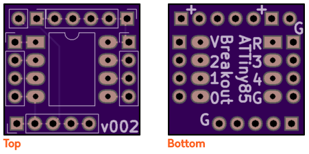
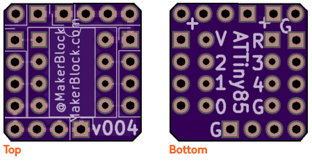
This series took me from knowing nothing at all about PCB layout and design to ordering my very first board through OSHPark. My first design isn’t anything amazing – it was basically a breakout board for an ATTiny85 to make it easier to build small projects.
My first ATTiny hacked tap light was a mess. I soldered wires directly to the microcontroller making it a real pain to update. ((I ask you – is this the work of a sane man?)) I soon realized my mistake and soldered an 8-pin socket in its place so I could reprogram the chip easily.
Mercifully, Shawn’s tutorial series got me up and running very quickly. This post is not meant to be a tutorial for KiCAD, but more like a “lab notebook” for the workflow to create a board. If you haven’t built a board yet, go check out Shawn’s series and follow along in KiCAD. If you are a novice like me, you might find these notes helpful:
Eeschema
If you launch Eeschema separately from KiCAD, you can save different versions of a schematic. Keeping old versions of design files is hugely helpful to me and if you launch KiCAD directly, the option to save different file names and versions is not available!
The keyboard shortcuts in Eeschema are great. With just a few, it’s possible to really get around quickly.
“Shift-A” and left click to place parts
“M” to move parts
“R” to rotate parts
It is necessary to add “PWR_FLAG” to both the power and ground lines.
Double check your connections work by clicking on the bug icon.
Assign the parts you intend to use to match up with the symbols using the “Assign PCB footprints” icon.
Save your work and “Generate netlist” to have something the Pcbnew will be able to work with.
Pcbnew
First configure the Design Rules by going to Setup -> Design Rules. Shawn pulled these KiCAD Design Rules from the OSHPark.com website. KiCAD has apparently changed a little since the version used on the OSHPark website, but the settings are easy enough to identify and change.
Minimum track width: 0.006. Minimum via diameter: 0.027. Minimum via drill: 0.013Custom Track Widths: Track 1: 0.03
Read netlist” to bring your design over from Eeschema.
Placing parts and drawing lines gets a lot easier when you fine tune the Grid. I started with 5.00 mils at first, then smaller figures to place smaller parts and features.
Once the parts are arranged in Pcbnew, connect the ground and power lines using 30 mil traces and everything else using 10 mil traces.
Create the outline for the board cutout by clicking on “Edge.Cuts” and drawing with the “Add graphic lines” tool. Starting with my second board, I began cutting the corners off, so that they were a little nicer to hold and
Label things on the “F.SilkS” and “B.SilkS” layers using the “Add text”‘ button. Since my boards are so small, I wanted the text to be a fair bit smaller than the default settings. I edited the text settings by going to Setup -> Text and Drawings.
Copper text thickness: 0.007. Text height: 0.035. Text width: 0.035.
Create a copper pour with Place -> Zone, then choose “F.Cu”2 and “GND”.3 and draw a box around your board. Then repeat for the “B.Cu” and “GND.”
Again, I’m a total newbie at circuit design. If I got something wildly wrong, please let me know. :)
I’ve always liked the idea of the Staples Easy Button. Not so much a button that says “That was easy,” but the idea of having an enormous button on my desktop that would do… anything at all. Official “Staples Easy Buttons” used to sell for about $20 and are now only about $7. But, this is still a lot to pay for a big button that I’d want to gut anyhow. Recently I figured out a way to build a big useful button, very inexpensively.
This slideshow requires JavaScript.
The secret sauce is … a tap light! You can buy a pack of 4 big (10cm diameter) tap lights for under $4 and they’ll ship free as a “Prime add-on.” For less than $1 each, you get a three AA battery holder, toggle on/off switch, a bright LED, all neatly organized into a big plastic button. This button also has another “feature” which is missing from many other pricier options. The dome over the light is white – which means you can put any color LED or, as I did, an Adafruit Neopixel inside and the dome will change color accordingly!
This slideshow requires JavaScript.
Here are some pictures of the disassembled tap light so you can see if it would work for you. I had originally bought these so that I could put a light right next to my newest 3D printer.123
This slideshow requires JavaScript.
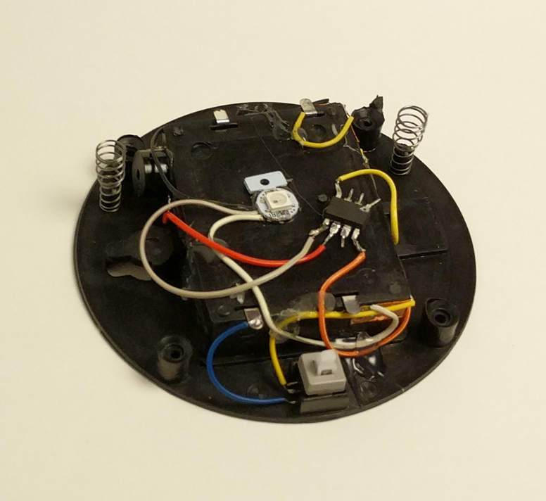
There’s actually quite a bit of room inside the tap light for a small project. I was able to pack a Neopixel, a small buzzer, an ATTiny85, and a rat’s nest of wires. I expect this project to take a lot of abuse at Maker Faire, so I applied a liberal amount of hot glue inside to hold the wires down and out of the path of the springs, switch, case, and the likely path of the button dome.
Once reassembled, there really isn’t any way to tell the button was hacked. It looks identical to three other tap lights. I just love that I was able to make use of the battery holder and existing switch inside the project. The 4.5V supplied by the batteries is perfect for powering my ATTiny85 and lone Neopixel. If you’ve got a junk drawer, you could probably build something very similar for about $2-3.4 As it is, I “splurged” by using $1 worth of Neopixel because I was being lazy and didn’t want to either wire up three sets of LED’s or track down three resistors to go with an RGB LED. Even so, this is an incredibly cost-effective project enclosure.
15 Second Timer-Buzzer
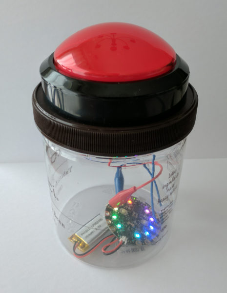
In case it’s of interest to you, this project is the newest iteration of our 15 Second Timer-Buzzer from my daughter’s 15 Second Drawings project for Maker Faire Bay Area 2017. The prior version used an Adafruit Circuit Playground, a 100mm Red Button, and a LiPo battery and probably cost around $40 or so. 5
All of the code is on Github. Basically, the buzzer flashes amber three times with a very short tone in between flashes, then turns green for 14 seconds, amber for one more second, and then turns red and buzzes angrily to let you know time is up. I had written most of the code to work on an ATTiny45… until the code ballooned to a whopping 4560 bytes and I had to switch to an ATTiny85.6 If I had to build this over again, I’d solder in an 8-pin DIP socket for the ATTiny rather than mutilating the chip and hot gluing it directly to the inside. ;)
Default Series Title
I have a power strip next to it, but it’s fully utilized, I only need a little bit of light sometimes, and I was getting tired of holding a flashlight on it at night [↩]
In my tradition of naming my 3D printers after characters from Futurama, my Monoprice Mini Delta is named “Roberto.” [↩]
I figure about $1 for an ATTiny85 and $1 for the button. Most people can find a way to scrounge an RGB LED or a few different LED’s, an old buzzer or piezoelectric disc, and some bits of wire [↩]
While I’m a big fan of paper and circuits, I’ve never really given paper circuits/circuitry a shot. Unfortunately, I have no good excuse for this. (Fair warning: I’ve been collecting links and ideas on this topic for several weeks now, and even though I intend to break up the post into more manageable chunks, I have a feeling this is going to be a doozy)
Years ago Chris Connors, a STEAM educator/maker and friend, had posted some photos and videos about something called, “TapeTricity” and helped hundreds of kids as young as 3 and 4 years old build their very first circuit at Maker Faire 2013. TapeTricity is all about making electronics accessible to people by showing them how to make real circuits using cheap and common components while removing the need for specialized tools and materials. This system of designing circuits made use of several very interesting innovations: aluminum HVAC tape and paperclips along the edges to form electrical contacts.
1. Aluminum HVAC Tape – Benefits and Limitations
Back in 2013 copper tape was reasonably common in artistic settings for use with soldering stain glass. However, the copper tape wasn’t readily available with conductive adhesive and tended to be more expensive than the aluminum HVAC tape used in Chris’ projects. While the prices of copper tape with conductive adhesive have fallen over the last few years and conductive inks/paints have become more common, pretty much nothing is going to beat aluminum HVAC tape for price per project. However, HVAC tape is not without its limitations. The adhesive is a decent insulator rather than a conductor, the tape only comes in strips about 2 inches wide and must be torn or cut to much thinner strips, and has a tendency to curl at torn edges, and aluminum tape does not take solder well.1 I expect that the non-insulation properties of the underside of the aluminum tape could actually be very useful in conjunction with copper tape – to essentially make for circuit board traces that can cross over one another.
2. Taped Edges – Contact Points
As you can see from some of the photos above, the edges of the cards had foil tape wrapped over some edges which were then connected to some of the components. The result is that the edges of the paper essentially become functional I/O pins. The nifty thing about this is that it could allow TapeTricity cards to be wired/rewired/networked together.
3. Paperclips – Alternatives to Alligator Clips
Another interesting feature of TapeTricity comes from the use of paperclips. Paperclips are ubiquitous and cheap23 and, with a little bit of wire, become cheap DIY alligator clips replacements. While individual alligator clips aren’t that expensive (let’s say around $0.25 each?), the cost of providing a number of them to a room full of students would quickly add up.
These TapeTricity cards allowed kids to color and draw on one side of an index card – then bring their designs to life with electronics on the back and through the card.
4. Lessons from TapeTricity
HVAC tape is a great choice for paper electronics with a few limitations. The adhesive is an insulator which allows HVAC tape to be leveraged in bridges and there aren’t easy ways to solder to it.
Edge conductive pads from HVAC tape allow for cards to be powered or networked
Paperclips and wire are a great cheap DIY alternative to alligator clips
2. Evil Mad Scientist Labs and Paper Electronics
Evil Mad Scientist Labs is one of my all time favorite open source arts/electronics designers/manufacturers ever. Not only do they enable other people to realize their plans for world domination, they’re pretty cool people. I had the good fortune to be able to visit Evil Mad Scientist Labs (now celebrating their 10th birthday!) a few years ago.
1. One Sided Circuit Board – paper, conductive ink, and soldering
2. Electronic Origami – several methods for electrifying paper
More recently, while researching for this blog post I discovered their simpler, but perhaps more spectacular, origami balloon circuit. EMSL posted several possible methods for electrifying paper. Since the post explains each of these methods in detail, I’ll only list them:
Using dry mount adhesive to glue aluminum foil to paper
Using an iron to fuse aluminum foil to freezer paper
Using an iron to fuse aluminum foil to the toner on laser printed paper
This circuit is beautiful and eerily reminiscent of a certain other cube. If someone hasn’t made an origami LED paper circuitry companion cube, well, this is just a thing that needs to exist in the universe.
3. Edge-Lit Cards
Another particularly cool post from EMSL is their piece on edge lit holiday cards. The electronics are essentially the same as a simple throwie or TapeTricity circuit, but the use of scored sheets of plastic allow incredibly interesting display possibilities.
4. Lessons from EMSL
In no particular order, here are some of the lessons I’ve learned from EMSL:
The conductive ink in the mobiüs circuit has enough resistance that the LED’s don’t really require actual resistors
Electronic paper projects need not be merely two-dimensional and adding a third dimension can be truly transformative
Scored or scratched plastic plus paper and carefully designed LED circuits can create amazing display possibilities
3. Paper Circuits / Paper Circuitry / Electronic Notebook
Just before Maker Faire 2016 I saw a tweet from Jeannine Huffman showing off her development of a paper circuitry robot panda which would cost about $5 per student.
I was astounded by what Jeannine was doing. Where TapeTricity was a great way to introduce kids to electronics, making those same electronics smart by adding a microcontroller could make those same pages smart and interactive. Moreover, a TapeTricity project could be “leveled” up by just wiring the aluminum contact pads to a microcontroller.
1. Jeannine Huffman’s Notebook
I was fortunate enough to be able to catch up with Jeannine at Maker Faire Bay Area 2016 this year and we compared notebooks. Here’s some pictures of her work:
To just jot down some of the problem solving and ideas I noticed in the few moments when we compared notebooks:
Mixing off the shelf electronic components and circuit stickers with conductive ink, copper tape, and soldering
Incorporating electronic components, sensors, and microcontrollers with DIY sensors, switches, and other solutions
Melding a notebook and electronics – by sketching in, around, and through circuits to provide annotations and instructions
Finding a way to create a copper tape hinge that could survive repeated opening and closing of the notebook
4. 21st Century Notebooking
The ideas shared in the 21st Century Notebooking Google Plus community are just too numerous for me to do justice. Since my blog posts are as much about me documenting my own discoveries as it is about sharing with you, gentle reader, perhaps you’ll forgive my jotting down just a few of the ideas found within a 30 second scan of this community:
UPDATE 10/26/2016:Jie Qi’s “paper-based electronics for creative expression” tutorials have some really great ideas for getting started with paper circuitry. Frankly, this is to be expected from the lady who created Chibitronics and circuit stickers. :) These tutorials are great – and you can see exactly how she refined these ideas to become circuit stickers and the kind of skill building projects seen in Chibitronics books. These tutorials include:
Project Daffodil is the work of Sian Geraghty, Robert Foster, and Christine Ho as their graduate thesis project for the Masters in Multimedia Program at CSUEB. Their project combines pop-up books, paper circuitry techniques, and 3D printing to provide an interesting introduction to electronics for kids. When I saw them at Mini Maker Faire Rocklin on 10/5/2016 they had combined their work with an iPad app which could interact with some of their 3D printed models infused with conductive material. They’ve been interviewed on the Make Magazine website and published a tutorial on building pop up paper crafts with electronics.
1. Lessons from 21st Century Notebooking, Circuit Stickers, and Project Daffodil
I think what I learned most out of these projects is that there’s a lot of ways to combine paper circuitry with other interesting and creative ideas like origami, paper crafts, greeting cards, pop up books, and 3D printing.
6. What’s Next???
Smart sketchbooks, electronic origami, and the ability to program anything. With all these incredible designs, pieces of code, and ideas – where can we go next?
Well, I have a few ideas…
Default Series Title
When I googled “how to solder copper wire to aluminum foil” the top result was a YouTube video which suggested applying a thin layer of oil to the foil, using a soldering iron with solder to heat up the foil, with the oil supposedly preventing the aluminum from oxidizing, then the wire could be soldered to the foil. [↩]
The crew over at Makeblock.cc were kind enough to send an XY-Plotter Robot Kit v2.0 my way for a review. I’ll be assembling the the robot and posting pictures of the process soon, but for now I wanted to do an unboxing preview for you.
1. The Box
This slideshow requires JavaScript.
The first step to any unboxing review must, necessarily, start with the box in which the product arrives. The box arrived safe and sound from China and was well packaged for transport. Most parts were wrapped in plastic, the electronics were in anti-static bags, and the boxes were nestled in thick foam padding. The blue anodized aluminum beams were mostly not wrapped in anything. There were no noticeable scratches on any of them. I did find a few blue anodized aluminum burrs from the parts in the box. Keep an eye out for them if you’re opening the package on carpet, as I did.
2. The Electronics
This slideshow requires JavaScript.
Above are the pictures of electronics. As mentioned earlier, each board arrived in its own little anti-static baggie. The card with the QR code to the instructions and rubber feet were a nice touch. At this point you’ll notice that the connector ports on all of the boards have colored coded stickers to assist with assembly. Clockwise starting at the top left corner, the box includes the card with the QR code to the instructions, three Me RJ25 Adapters, two Me Steper Driver v1.0 boards, an Me Baseboard, and four sticky-backed rubber feet.
3. The Tools
This slideshow requires JavaScript.
Clockwise starting at the top left corner, the box includes RJ25 cables, a USB micro cable, three timing belts, three micro switch buttons, three lasercut acrylic “LS” brackets for the micro switches, 11 tiny screws, one lasercut acrylic “servo bracket,” another RJ25 cable, a small Philips screwdriver, a 2.5mm hex screwdriver, a 7mm wrench, two 1.5mm hex wrenches, a Micro Servo, a lasercut acrylic “Baseboard,” and one Beam 0808 72/80 aluminum beam.
4. The Hardware
This slideshow requires JavaScript.
There are a lot of hardware parts in the main cardboard box:
Shafts
2x D shafts, 4 x 56mm
1x linear motion shaft, D4 x 80mm
1x threaded shaft, 4 x 39mm
Flexible coupling, 4 x 4mm
6x timing pulleys 18T
8x flange bearing, 4 x 8 x 3mm
43x M4 nuts
25x plastic ring, 4 x 7 x 2mm
6x cutable linkage 3, anodized blue aluminum
6x linear motion slide unit, 8mm
Beams
4x Beam 0824 48
1x Beam 0824 80
4x Beam 0824 96
2x Beam 0824 112
2x 42BYG Stepper Motor Bracket
2x bracket, 3 x 3
4x plate, 3 x 6
5x bracket, U1
3x belt connector
1x Beam 0828 16
1x 42BYG Stepper Motor
12V DC power adapter
1x 42BYG Stepper Motor
31x socket cap screw, M4 x 14
28x headless set screw, M3 x 5
28x socket cap screw, M4 x 16
6x plastic rivets R4100
18x plastic rivets R4060
10x shaft collar, 4mm
18x socket cap screw, M4 x 30
12x socket cap screw, M4 x 22
30x plastic zip ties and 5x rubber bands
36x socket cap screw, M4 x 8
3x cross recessed pan head screw, M2×10 and 3x M2 nuts
10x countersunk screw, M3x8
The last picture in the set depicts all the really long pieces of the robot – the linear shafts and beams. In order, from top to bottom, they are:
2x Beam 2424-504
2x Beam 0824 496
4x linear motion shaft, D8 x 496mm
1x linear motion shaft, D4 x 512mm
Default Series Title
Disclaimer: This robot kit was provided by Makeblock.cc for the purposes of unboxing and review. They have asked that I provide my honest assessment of this kit.
My overall designs for a printable parametric hand are still far from done. And, yet, I’ve come a long long way since jumping headfirst into the realm of open source prosthetics a little more than 30 days ago.12
Forgive the digression, dear reader, before I return you to considerations of prosthetics. After visiting the Asian Art Museum today with the family, I am feeling particularly inspired to discuss dualities.3 I find I am an often-inspired person. This is a very charitable way to describe myself by what would otherwise colloquially and clinically be considered ADHD. When I am inspired by a new topic, I tend to jump right into it – reading voraciously and trying to learn as much about it as I can. When this happens, I also tend to set aside whatever thing I was most recently working on. This means that recently I’ve done little work on drawing robots (big and small) and a multitude of other small projects that would otherwise be just amazing. However, such inspirations/distractions are not only external to a project – but can also be very much internal to a project. Consider, for instance, feature creep – the adding of ever more features to a project, usually at a faster rate than which features are resolved and refined. In order to combat this aspect of my nature, the wanting to add more and better features, I have developed a coping mechanism. To prevent myself from falling down the rabbit hole of features and improvements, I jot them down someplace – either in a blog post4 , in an email to myself, or in a notebook.5 I find that once I’ve externalized and memorialized an idea, I can continue working on a project unfettered and undistracted these other ideas.
To this end, and in the spirit of open source ideals, I will jot down some ideas while I have them:
How large and how small are prosthetic designs typically scaled?
I wanted to have a range of sizes for which my designs were optimized. My guess would be no smaller than 85% and not much more than 160% of the size of the existing Cyborg Beast. Jorge Zuniga was, again, patient enough to discuss this with me. His estimate of a range would be between about 105 – 150%.
What is the diameter of the Chicago Screws typically used in the creation of a Cyborg Beast?
From the retailer’s website, it appears the “barrel” diameter is 0.2 inches, or 5.08mm. I’ll need to make some adjustments to holes for the Chicago Screws in the designs.
How important is hyperextension of these fingers?
The designs of the Cyborg Beast include fingers that can bend “backwards” very slightly. Each finger joint includes a “stop” at the back of the joint. While certainly useful, I question their necessity. I previously designed a connection system for printable snap-fit parts ((For use in an equally noble project)) that connect very tightly and/or bend with a user specified degree of movement. The point with me mentioning these parts is that the “stop” used at the back of each knuckle and joint in the Cyborg Beast may not be necessary at all.
How necessary are metal Chicago Screws to strength and durability of the hand and fingers?
Before you laugh, consider this question – what is the weakest point of any given finger which uses a metal Chicago Screw when having to deal with lateral forces? I would postulate the weakest points would be those thin plastic parts surrounding the Chicago Screws themselves. Thus, even though the hand incorporates metal pins, I have to wonder just how much strength they are providing to the overall device. It would be easy to conceive of a plastic prosthetic hand that was so small that there wasn’t a lot of plastic around each metal screw6. In such a case, the weakest points would be plastic surrounding the metal parts. Extending this conjecture, of what use are metal fasteners to a design that is primarily plastic? The best guess I can offer is that they allow reliable and smooth operation.
Work on proportional fingers
In designing the fingers, I worked to be able to make them customizable in several different ways. The user may specify whether the fingers have the “star grip” pads, whether the finger should be slightly shorter or longer, and scale the finger up or down – without distortion to the hardware and cord channels.
I need to add at least three additional options to these parametric designs. The designs should include the option to add “mouse ears” and easily removable support structures. Additionally, the design should also allow the user to change the diameter of the finger. I did implement this, somewhat, in part of the design. Without implementation throughout the entire design, these partial attempts aren’t helpful.
In creating the fingers shown above, I adjusted their lengths to conform to the measurements of my own hand.7 Next time, I think I would also measure finger diameters.
I think I should create a way to prevent finger parts from being mixed up accidentally while printing. A possible solution is to include “mouse ears” with each finger – but embed an identifying mark in each mouse ear to label the parts.
Ideas on making a better parametric palm
The palm should be redesigned so that the fingers, at the appropriate lengths, would fit into it. I designed the fingers quite a while since working on the palm. I haven’t had a chance to ensure the parts would mesh well without adjustment to the scale.
On an entirely different note, I have an idea to redesign the entire palm. By carefully placing deformed spheres, I was able to design a palm. Using a similar process, I subtracted out a void for the user’s hand. The result is a palm with an uneven thickness throughout. Uniform thickness isn’t necessarily an interesting or useful goal. That said, it could lead to a reduction in unnecessary plastic. If I were to redesign the palm, I could design the internal area first8 – and then use the “Minkowski” function to create a uniformly thick shell around the internal form. The bottom would have to be sliced off and the original internal area would need to be subtracted from it.
Ideas on making a more realistic hand
My designs so far are based primarily on the Cyborg Beast, with some minor changes. The “Flexy-Hand” appears to be very organic and realistic. It also features flexible printed connections between each finger segment. Additionally, each finger is comprised of three segments – rather than two like the Cyborg Beast. Interestingly, since the flexible connections between segments allows the hand to return to an “open” position, the hand only requires five tension cords – rather than five tension cords and five elastic cords. The fingers appear to not have any “stops” behind each joint. I have to wonder how having three segments to each finger impacts the function. Does it allow the hand to better grip things? Does it make the hand less sturdy?
Masculine/Feminine hands
One well-intentioned comment to my latest designs is that they are “pretty.”9 While I accept the compliment with the spirit in which it was given, it immediately made me wonder – is the hand I designed “feminine?” Then it occurred to me that with more design effort, I could make “feminine” and “masculine” version of these hands. I think the primary differences would be two-fold – thinner fingers and a less “hefty” palm for a more feminine version and a thicker and perhaps more “blocky” palm for a more masculine hand.
New developments
There have been a number of interesting and new developments and experiments of late.10 In no particular order, these ideas are:
A few days ago my daughter and I were jotting down some ideas in my sketchbook. As we did so, she saw some of the notes from the e-NABLE meeting on 3/21/2014 – including several sketches. We discussed the problem – affordable, customized, and comfortable prosthetics. We talked about amniotic band syndrome, how fibrous amniotic bands affect fetuses, and the different ways in which these bands can cause11 deformities to single fingers, whole hands, and a range of changes in between. I explained how Mr. Jose Delgado Jr. had a $42,000.00 myoelectric prosthetic, the problems he has with that prosthetic, how and why he prefers his $50.00 printed replacement, and how for the price of his one prosthetic people could make 840 more prosthetics.12 She asked, “Why can’t someone use a stump to operate a hand?” I replied that this was exactly how these prosthetics worked – and I drew a few simplified sketches of the Cyborg Beast. Her next question was, “Why can’t it move side to side?” I said that Mr. David Ogreman had designed such a prosthetic.
Default Series Title
My first concrete step was going to an e-NABLE meeting in San Francisco on 3/21/2014. [↩]
The above picture is slightly misleading. I haven’t confirmed that the fingers I’ve designed will properly fit into the palm that I’ve designed – or that the thumb would work at all. Thus, the picture is partially a parlor trick and partially an indication of where I hope to take this design. [↩]
Many of the gods and goddesses in Eastern religions embody dual natures – creation/destruction, life/death, etc [↩]
In one of my several different blogs. Besides, what could be more ADHD than having 3+ blogs?!? [↩]
You may not find this as amusing as I do – but I probably have about four different sketch/notebooks. [↩]
I don’t even know why I’m saying “of late” when I’ve really only been involved a little over 30 days. I guess becuase these developments are new to me? [↩]
Please forgive my lack of a more politically correct term. If you’ve got a better or more sensitive phrase, please let me know as I will gladly adopt it [↩]