Fire the DrawBot!

Last night I connected my newly designed pen holder to my finished drawing robot and attempted a relatively “quick” drawing of Yoda.  I say “quick,” because it only took about two hours.  The one lone trade-off for having an cheap and easy to build robot capable of essentially unlimited drawing sizes is that it can take a long time.  I took several photographs of my robot while it was drawing and turned them into an animated GIF, featured at the end.
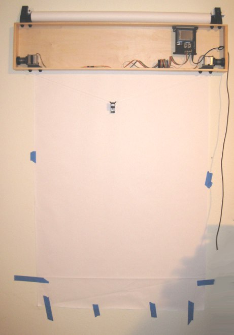
Finished and mounted robot, with old pen holder

Finished and mounted robot, with old pen holder

Above is the robot itself, mounted to the wall.  I’ve made two minor changes to this setup since that photo, detailed just below.  First, I’ve placed a large sheet of sacrificial cardboard under the paper so that any pen leaks will not mar the wall.  Second, since the “home point” (exactly 130mm down from the exact midpoint between the two spots where the cord leaves the project box) is hidden by the paper when I pull it down, I needed a way to be able to center the robot without having to re-measure the home point each time.  My solution was to take a small piece of leftover plastic about the size of a pinhead and tape it to the home point on the cardboard.  Now, I can feel the home point through the sheet of paper and center the pen holder accordingly.
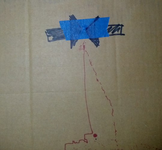
Home point for centering the pen holder

Home point for centering the pen holder

It’s a little difficult to make out in the photo above, but you can see the two big arrows pointing to the home point and a slight bulge in the tape caused by the small plastic speck.
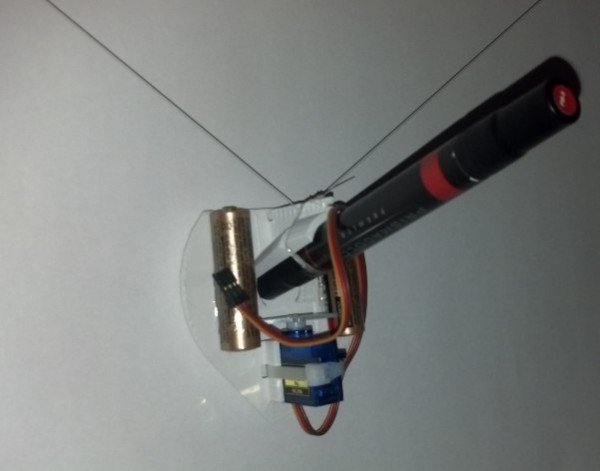
Brand new pen holder, assembled

Brand new pen holder, assembled

This picture shows the pen holder fully assembled.  I operated it the first time without the benefit of a servo motor cable.  I wanted to see if the pen holder would work well.  Once the drawing was about 2/3 done and I was pretty happy with the pen holder’s operation, I soldered up a cable to connect the servo lift port to the servo motor.
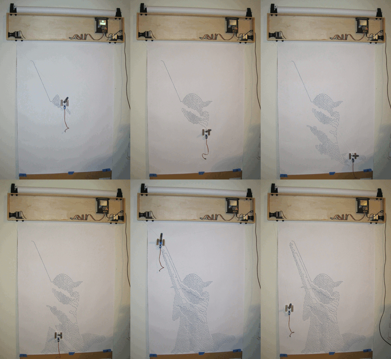
Drawing robot in action

Drawing robot in action

The above animated GIF is comprised of eight separate photos from my digital camera on a tripod, combined in GIMP.  I’ve never to make an animated GIF from a series of photos, but it very quick and painless.  Since video takes up a lot of space and battery power, I figured a series of photos would be the easiest way to create a “time lapse” of the robot’s operation.  You don’t get the low drone and hum of the motors, but you can see how it operates.  Now that I’ve done one, I’m looking forward to making more of these.
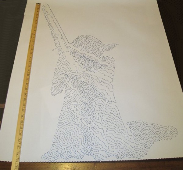
Yoda, standing tall

Yoda, standing tall

And here is Yoda!  As you can see from the ruler next to him, he’s about 35 inches tall from the tip of the lightsaber to his feet.  There’s a “band” of the drawing that appears to be shifted downwards slightly, causing a little overlap at the bottom of that region and a slight gap above.  This is probably due to me fiddling with the robot, but it could also be due to the motors slipping or skipping slightly during operation.  If it was due to me fiddling with the robot, then the fix is simple – I just need to be more patient.  If it was due to the motors skipping steps, then turning up the pots just a little would probably fix that.  Given that this is the very first drawing from my very first draft of a new pen holder, I’m really happy with the result.
Ideal Qualities in a Drawing Robot Pen Holder

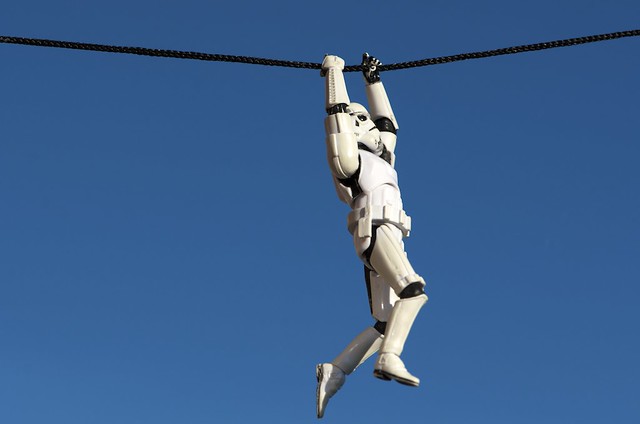
Even something as cool as this...

Even something as cool as this…

In my last post I tried to list off as many uniquely designed drawing robot pen holders as I could find.  The reason for documenting them as I did, and pointing out certain design choices, was to help me identify ideal qualities in a drawing robot pen holder.  Before I dive too far down this rabbit hole, I should mention that Stuart Childs has an excellent post on his site discussing the particular challenges faced by those who seek to design a pen holder.

Before we can talk about how what makes a good pen holder, we have to agree on some of the terminology:

  1. Pen holder.  This is just the device that holds the pen and hangs down against the paper for drawing.  While it is sometimes called a “gondola,” I’ll refer to it as “pen holder” in this post.
  2. Cord.  Different drawing robots use different methods for controlling the gondola.  Some use monofilament fishing line (as is my preference), others use toothed belts, some use beaded cords.  For ease of reference, I’m just going to use the word “cord” to refer to whatever method might be used to connect your pen holder to the motor spools/sprockets.
  3. Hanging triangle.  When you draw an imaginary line between the two stepper motors, the cords from each motor meet at a point on the pen holder, forming a triangle pointing downwards.1
  4. Cord convergence point.  The “cord convergence point” is the, sometimes imaginary, point where the two pieces of cord meet to form the tip of the hanging triangle.  Many times the cords don’t actually physically meet.  In those cases, the “cord convergence point” would be the point where the two cords would meet if both cords were perfectly straight lines that continued through their point of attachment to the pen holder.
  5. Up / Down / Left / Right.  These directions will assume your robot is mounted to a wall/large sheet of plywood and you are facing the wall.  ((This could cause a mention of a “pen up” to be confusing, so I’ll try to avoid this phrase))
  6. Forward / Back.  Again, assuming you are facing a wall on which the robot is mounted, forward here would mean going towards the wall and back would mean moving away from the wall.

Without further ado, a list of ideal qualities in a drawing robot pen holder.  While not in any particular order, I’m listing them by number for ease of reference later.

  1. Secure pen holder.  The pen holder must, as you might imagine from it’s title, hold the pen used for drawing.  If it doesn’t hold the pen securely, you’ll get squiggly lines when you don’t want them and really squiggly lines when you only want somewhat squiggly lines.  It is important to note that a pen should be held securely so that it doesn’t move around left/right/up/down or back and forth.  Even if a pen is held securely with respect to left/right/up/down, it could still accidentally be pushed back (or, I suppose get pulled forward?) causing the pen to not touch the drawing surface (or always touch the drawing surface) despite pen lifts.
  2. Adjustable pen holder diameter.  An ideal pen holder should be able to hold a big fat marker or a teeny tiny marker.
  3. Adjustable pen position.   I’ve noticed that some pens are a lot narrower near the pen’s tip.  Thus, some pens will need the pen tip to be closer or farther from the wall, depending upon it’s own characteristics.
  4. Adjustable tilt to pen.  Although markers can pretty much draw at any angle, other pens (such as ball point or gel ink) just won’t work when they’re nearly horizontal.
  5. Incorporate a micro servo.  Single line drawings are really awesome – but with the addition of a micro servo for pen lifts, the robot becomes infinitely more versatile.
  6. “Depth” of pen holder.  Just to choose a term, this would be the distance the pen holder sticks out from the wall.  To strain the metaphor, the “shallower” the pen holder the less it can tilt or tip front/back or up/down.  Conversely, the “deeper” the pen holder, the more it could tilt or tip as it moves.
  7. Distance of center of gravity from wall.  This is an interesting one.  When I started building my robot, I thought the best thing to do was to have the wires leave the project box as close to the wall as possible – so that they would “encourage” the pen holder to hang closely to the wall.  Then I realized that it was actually equally important to achieve a balance of the pen holder.  With most of the considerations here, I can pretty much determine whether it is better to choose a configuration one way or the other.  Unfortunately, with this issue, I can’t decide whether it is better to have the pen holder’s center of gravity close or far from the wall.  Of course, not knowing won’t stop me from pontificating, eh?
    1. First, let’s agree there’s no apparent benefit to having a pen holder designed so that it is “deep” and balanced such that the center of gravity is farther from the wall.
    2. Second, the only apparent benefit I can think of to have a “shallow” pen holder is that it might reduce tipping/tilting somewhat.
  8. Adjustable line attachment points.  As the weight of the pen holder changes, so would it’s center of gravity.  Thus, the attachment points should also change.
  9. Adjustable weight.  Weight is one of the more finicky variables.  If the pen holder is too heavy, the motors will have a harder time, require more power, and be noisier.  If the pen holder is too light, there may not be enough pressure against the drawing surface, the cords may not be held taut (and thus will not behave as the program expects them to), it won’t be as responsive to the tugging of the two cords, and will tend to tip up or down or bind against the wall.
  10. Balanced pen holder.  An ideal pen holder should be balanced so that it doesn’t want to tilt left/right, up/down, or forward/back.
    1. In this video from Darcy Whyte’s site you can see how a pen holder that appears to not be balanced well tends to tilt or tip in response to a change in direction – essentially pivoting around the pen’s tip.  When this happens the pen either doesn’t move as much as the program expects causing certain features to be too short or the lines and curves drawn will appear to have a “stuttering” quality caused by the pen not moving with the cord because the pen tip is binding against the wall and then releasing suddenly and going too far.
    2. I used to think it would be more advantageous to have slightly more weight on the forward side of the pen holder – now I’m not so sure.  What I used to think was that by having the front end of the pen holder heavier, it would somehow exert more force on the wall.  However, there really isn’t any logical reason this should be the case.  Or, until I put a force sensor on the wall and test it, I don’t think I can claim this to be the case.  Watching videos of drawing robots and my own drawing robot in action, I now think that a very light touch on the wall might be more ideal.  Let’s assume any decent pen, especially markers, aren’t going to require a lot of force to leave a mark.  The more force with which the pen is pressed against the wall, the more likely the pen tip is to bind against the wall and draw stuttering lines or lines that are too-short.  Meanwhile, a very well balanced pen holder that is lightly pressing against the paper should not bind at all, resulting in more accurate lines.
  11. Points of contact.  There are any number of different designs for pen holders.  Some of them only touch the drawing surface with the pen tip (like the Der Kritzler, AS220 Labs and GarabatoBot), while others tend to have three points of contact (such as Makeangelo 1 & 2), and some basically have a large wide flat surface which meets the drawing surface (Polargraph, Mr. Drew, and DRBO).  My original mis-use of John Abella’s pen holder design actually had two points of contact – the pen tip and then the sack of batteries that hung from the holder.  A few comments about these different styles:
    1. One point of contact.  This single point of contact will always be either the pen tip or device used to create a pen lift.  Either way, the resulting pen holder can easily tilt left/right, back/forward, up/down, or any combination no matter how well balanced.  If you’re going with a single point of contact design anyhow, I suspect a well balanced and “deep” pen holder might work best.  Here, by deep, I mean a pen holder that sticks out from the wall.  My suspicion is that dialing in the pen’s balance, you might be able to achieve a favorable angle of pen-to-paper.  Having a “deeper” pen holder would allow more room for the robot operator to adjust the cord attachment points.
    2. Two points of contact.  This is just a bad idea – just don’t do it.  The way I implemented this involved a weight hanging below the pen tip.  When the pen moved too fast, the weight would swing causing a pendulum like wobble in the drawing.
    3. Three points of contact.  This seems, intuitively and by observation of Dan Royer’s videos, to be a stable pen holder design choice.  The two extra points of contact (in the case of Dan’s Makelangelo below and to either side of the pen tip) prevent the pen holder from tilting back/forth, left/right, or even up/down.  A three point of contact pen holder could still have a sway left/right problem, but that’s so bad if it means you’re eliminating all that tilting.
    4. Full contact.  This setup, like the three point contact, eliminates any form of tipping and is possibly less susceptible to left/right swaying.  Unlike the single point of contact setup, I think this kind of pen holder might benefit from being shorter (as in doesn’t stick that far out from the wall)

      ...can be drawn by something as ugly as this

      …can be drawn by something as ugly as this

  12. Cord attachment points.  There appear to be about several different ways of approaching cord attachment to the pen holder.
    1. The cord convergence point is exactly at the pen tip.  This kind of setup requires nice big bearings or metal tubes that allow the cord attachment points to rotate around the pen tip.  As the angle where the two cords meet changes, the two cord attachment points rotate to accommodate.  Getting the cord convergence point to be centered on the pen tip is much more complicated to design and expensive to build.  Look to the Polargraph and Ragnar drawing machine for examples of this type of design.  This is particular design choice does not introduce any distortion.
    2. Off-center but close together.   This is a very simple and extremely common method of cord attachment.  Each cord is connected to the pen holder a little to the left and a little to the right of center with the pen usually a little below that.  As long as the two cord convergence points aren’t really far apart, this method will introduce very little distortion.  Additionally, by having the two cord attachment points separate, this kind of pen holder enjoys a little extra stability.
    3. Single cord convergence point, not at the pen tip.  I have not been able to find any pen holders that use this method of cord attachment.  It would basically involve using a single point of cord attachment, either by simply tying the two cords to the same point or by using two pivoting arms as with the Polargraph or Ragnar drawing machine.  Rather than the pen tip being at the same point as the cord convergence, the pen tip would be at some point a constant distance and position from the cord convergence point.  I think the reasons this type of holder isn’t seen is that it is so easy to build an “off-center but close together” style pen holder, any distortion with the “close together” method is extremely small, and having the cord attachment points separate provides the added benefit of a little extra stability against tilting.  However, as long as stabilizers (three point of contact or full contact) are used, there shouldn’t be any reason not to employ a single cord convergence point.
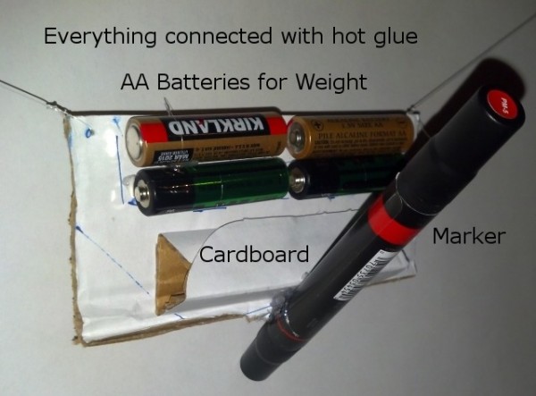
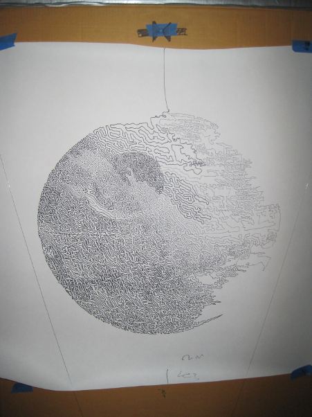
    4. Devil-may-care.  The big Deathstar at the top of the post was drawn by the ridiculously crude pen holder pictured above.  Even with the cord attachment points being 120mm apart, the results are really great.2 Building a pen holder with this design choice will introduce some distortion.  It’s unlikely someone is going to be as foolish as I was to build a pen holder with cord attachment points as wide as 120mm.  However, even in such an extreme case, the distortion was shockingly small.
  13. Location of weights.  While I haven’t done any tests on this, I’m fairly certain that having the weight of the pen holder as tightly packed around the cord attachment point as possible is most advantageous.  The last thing you want is for an off-center weight to cause the pen holder to sway during a direction change.

Enough talk!  I think it’s time I start actually designing a pen holder!

Default Series Title
  1. This is a term I only learned today from the context of Sandy’s comment in an earlier post.  This term is just so perfect and useful in describing drawing robot set-ups, I just have to include it here. []
  2. Unfortunately, the Sharpie started to run out of ink about 2/3 through the picture, which does detract from the drawing somewhat. []

Drawing Robot Pen Holders, Calligraphy Pens, and Thought Experiments

Just hanging out

Just hanging out

In discussing Sandy Noble’s Polargraph pen holder I mentioned how his design is optimized so that the point where the two cords meet is always the same as where the pen tip meets the paper.1 In the comments, he explained his rational, “So the pen tip is always at the tip of the hanging triangle, and there’s no distortion that way.”  My response was that “…if the pen holder has a single ‘hanging triangle’ point in it with the pen tip a constant distance from that ‘hanging triangle point,’ the drawings should appear identical to those created at the ‘hanging triangle point’ – just offset by the constant distance.”

This morning Sandy updated his site with a post explaining, using several diagrams, the basis for his prior theory and how he came to agree with my point. (Not that he’s changing his pen holders…  ;)  )

Without as much fancy-schmancy maths and geometry, I figured I would explain the thought experiment I used to conclude that a pen tip that is always a constant distance and position from the “hanging triangle point” will always produce an accurate distortion-free drawing.  To help illustrate these thought experiments, I’ve enlisted the help of Yoda.  “Hi Yoda!”

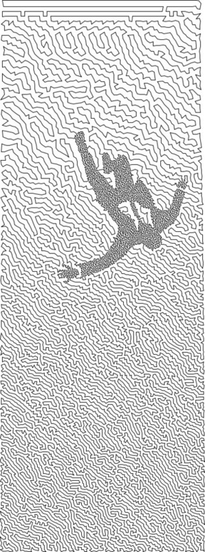
Fig 1:  Yoda, being drawn by a drawing robot

Fig 1: Yoda, being drawn by a drawing robot

In the picture above, Yoda is being drawn by a drawing robot.

Fig 2: Yoda drawing, annotated

Fig 2: Yoda drawing, annotated

Above, I’ve labeled the important parts of the drawing.  On the top left “Motor A,” on the top right “Motor B,” which are attached by cords to the pen holder indicated by the dark blue line.  Here, I’ve shown Yoda as he would be drawn by a drawing robot, where the robot then draws two more points.

Let’s say, because we’re feeling whimsical today, we want to add a second pen to our pen holder.  We’ll use a red pen and affix it below the blue pen in such a way that the red pen will always be directly below the blue pen by the same distance.

Fig 3:  Another pen

Fig 3: Another pen

For the moment let’s pretend the red pen is capped so it won’t leave a mark.  Now we’ll try to predict the position of the red pen at different points along the original drawing.

Fig 4: Where's the red pen?

Fig 4: Where’s the red pen?

It turns out this task is pretty easy.  The red pen, at any given point during the Yoda drawing, will always be directly below the blue pen by the same exact distance between the two pens.  Okay, now let’s draw Yoda again – this time with the red cap off.

Fig 5: Double vision

Fig 5: Double vision

We get two Yodas!  How awesome is that!  The reason I mentioned calligraphy pens in the title of this post is because it shows another way to think about this process.  When we write with a calligraphy pen we don’t have one end of the pen wildly distorted – in theory the two points on the calligraphy pen are always a constant distance from one another and moving together (as long as we don’t rotate the pen when we write).  You could imagine instead of a blue and red pen above, we’ve put a single calligraphy pen that’s as wide as the black line representing the distance between the two pens above.  The resulting drawing would look like a Yoda – that had been smudged downwards by the same distance.

Let’s now draw Yoda again, but capping the blue pen and still tracking where the blue pen would be.

Fig 6: Not using the blue pen

Fig 6: Not using the blue pen

We should end up with a result very similar to Fig 4.  It’s the same Yoda, only red and shifted down from the original blue Yoda by the distance between the two pens.

Let’s draw Yoda again – this time we’ve still got a pen holder which has the cord from Motor A meet Motor B at exactly one point.  As Sandy points out, this is really easy to do when you aren’t worrying about making that exact point be the same precise point as the pen tip.  Directly below point where the two cords meet on the pen holder, we’ll put the red pen.  From a functional standpoint, this setup is identical scenario to Fig 6.

Fig 7: Drawing just one red Yoda

Fig 7: Drawing just one red Yoda

Now we have a red Yoda, shifted down on the paper by the distance between the point where the two cords meet and where the red pen touches the paper.  It’s important to note that there’s no special magic to having the red pen directly below the point where the cords converge.  This pen tip just needs to be a constant distance and position from the cord convergence point at any given time.  While it might be more difficult to build a pen holder that holds the pen far off to one side, there’s no reason this wouldn’t work.

Fig 8: Yoda, now in green

Fig 8: Yoda, now in green

The lessons I take from this thought experiment are:

  1. As long as the pen is a constant distance and constant position from the point where the two cords meet, your drawing will not appear distorted – just shifted by the same constant distance and position.
  2. When calibrating the robot, the operator would need to calibrate the pen holder position by the cords convergence point – not the pen point.  This means that the preview in your software won’t match exactly the position of your drawing on the paper.  
  3. While not part of the thought experiment per se, I think we can all agree that the more weight that is not centered on the cord convergence point, the more likely the pen holder is to sway.
  4. I’m willing to defer to Sandy’s experience that pen holders that do not have the cord convergence point the same as the pen tip are, “Easier to design, easier to build, and cheaper, far, far cheaper.”

Thanks Yoda!

P.S.  Just in case you’re wondering – the reason that SVG of Yoda above is so large is because it includes the full TSP version of Yoda I’m getting ready to draw.  :)

Default Series Title
  1. Photo courtesy of Kristina Alexanderson []

Two new DrawBot links! And an update!

Thanks to Dan Royer, I’ve added two new links to my really huge list of DrawBots.  That brings the total to 28 drawing robots! 1  That’s a really incredible number of people who have shared documentation for their hard work.  Six months ago I wouldn’t have guessed there were more than a dozen such projects on the ‘net.  Clearly, the six-month-younger version of me is a fool.  Thank god I know better, eh?

So, Dan appears to be using an Arduino + Adafruit motor shield, much like I’m using, but he’s running custom Gcode software with a Java GUI.  It looks like Dan was wrestling with the problem of how to maximize drawing speed without causing his ‘bot to hang over the serial connection.  If he gets some decent speed out of his setup, I’m definitely going to give that a shot.

Unfortunately, I haven’t done much in the way of robotic drawings lately.  After experimenting with TSP drawings and finding out they would take an excruciatingly long time I set my drawbot aside for a little while.  Fortunately, Sandy’s been on the case and has worked out a new firmware version that might prove to be twice as fast as the one I’m currently using.

Default Series Title
  1. <queue thunder and lightning> 28! 28 drawing robots!  Ah-ha-ha-ha-ha! []

Speedier DrawBot Drawings

When using my DrawBot to draw pixelated drawings (versus TSP or vectors)1 I don’t really notice a pause from the machine between each pixel.  It takes a few seconds to shade each pixel, then it moves to the next spot and starts over again.  However, when trying to draw TSP art I discovered that the time spent shading a picture obscured the amount of lag time that occurred between each drawing point!  As I tried to draw a TSP portrait of my family I found it was taking about 3 seconds between each little point – which translated to a VERY VERY long time for a VERY small drawing.

When I asked Sandy about this, he suggested that this lag would be eliminated by drawing from an SD card.

Sandy’s current setup, which allows for computer free printing, consists of an Arduino Mega 2560 R32 , a MicroSD card breakout board3 , and an Adafruit Motor Shield4 .  Thus, the electronics setup would cost about $100 if you were starting from scratch, or another $80 if you have been following along at home and have a similar setup to mine.  Apparently the problem is you can’t just shove a MicroSD card into an Arduino.  If you try to add one to an Arduino, then the card shield will end up taking up the pins necessary to use the Motor Shield.  Since the Arduino Mega has a lot of extra pins, some of those can be used towards accessing the MicroSD card.

However, I thought I had seen an Arduino that had a MicroSD slot on board. 5  When I searched around Adafruit, I found this Ethernet Shield R3 with MicroSD connector6 .  Not only does this little shield fit my existing Arduino Uno, have a MicroSD slot, and have an Ethernet port, but it also has input pins so that it can be stacked!  This makes me then wonder…  Could I just pop this $45 board between my Arduino Uno and Motor Shield, add some software and get cooking?  I have to admit, the idea of spending $45 more, rather than $80 more for a Mega and MicroSD breakout board appeals to me.  I suppose there’s the added benefit that I might be able to run a REALLY long ethernet cable to the ‘bot if I so desired since it would have a built-in ethernet port on the Ethernet Shield.

Now, I’m the first to admit that I know next to nothing at all about programming Arduinos or fiddling with such things.  I’m just a fair hand at slavishly following some other person’s excellent directions.  Please do me a favor and let me know whether you think adding this Ethernet shield between my Uno and the Motor Shield will or will not work.

Default Series Title
  1. Actually, the TSP drawings ARE vector graphics… []
  2. $65 at Adafruit []
  3. $15 at Adafruit []
  4. $20 at Adafruit []
  5. Spoiler alert: I was wrong []
  6. $45 at Adafruit []

TSP FTW!

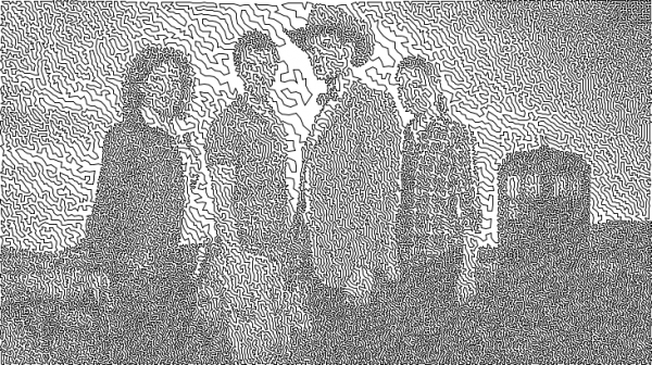
Doctor Who Season 6 TSP Single Line Drawing

Doctor Who Season 6 TSP Single Line Drawing

I have been having SO MUCH FUN with traveling salesman problem / single line art!  I can’t wait to draw some of these with my DrawBot!

And, really, how much more perfect could this project get?  It’s a TSP nerdy math single line art drawing of my favorite sci-fi show for drawing with a robot I built using printed parts from my 3D printing robot. 1 2 3

Default Series Title
  1. Oh, nirvana! []
  2. I suppose the only way to make it better is to draw the image on a pizza using spray cheese. []
  3. Actually, I take that back.  Ew. []