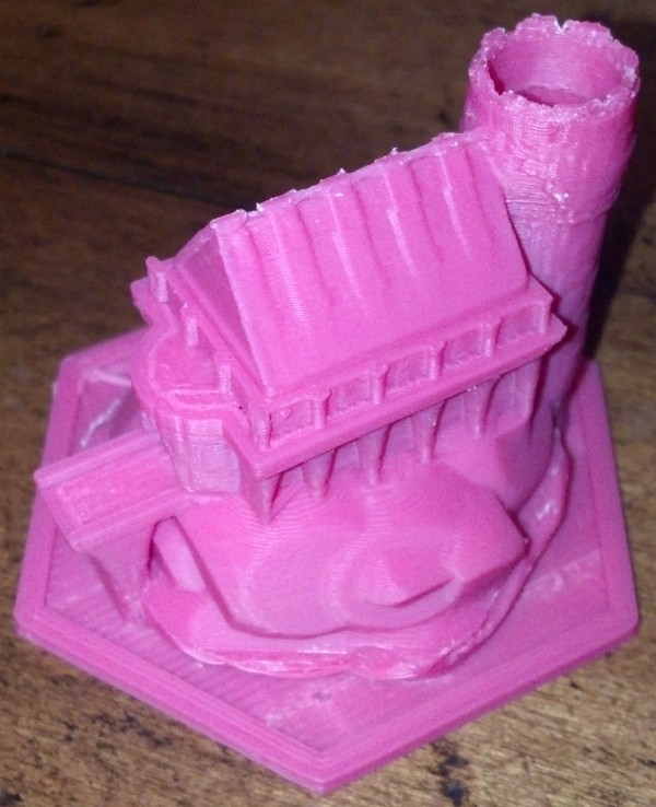
Two days ago I designed a new type of pen holder for my drawing robot based upon what I had learned from examining the pen holders other people have designed and used.
Here’s what worked and what didn’t:
- WORKED: The fit. I’m really happy with how the pen holder went together. It’s always very satisfying to print a part you just designed and have it “just fit.” With the zip tie holding the micro servo in place, neither the micro servo tab nor the zip tie protrude beyond the flat surface of the pen holder. The groves for the rubber band to hold the pen in place work very well. The pen doesn’t move side-to-side, get pushed back into the holder, and it is very easy to reposition the pen or change pens entirely. While it’s not as elegant as, say, a metal spring, it works very well and doesn’t require a bunch of moving parts.
- WORKED: The amount and placement weight. I hot glued a AA battery to either side of the pen holder, as close to the center as I could manage around the hole for the pen. This weight seemed to work perfectly. There was enough weight that the cords hung in straight lines, but not so much that it seemed to cause a strain on the motors. The placement of the weights seemed to work well as there was no noticeable pendulum swinging of the pen holder, despite me running the robot at about three times it’s usual top motor speed and about twice it’s normal acceleration.1
- WORKED: The multiple points of cord attachment. Having a row of holes for connecting the cords at different points along the top central edge of the pen holder worked out great. To test the balance all I did was stick a small paperclip through a hole. If the holder balanced with the flat edge upright and vertical, that’s the point I needed. It was easy to find the balance point and easy to connect the cords.
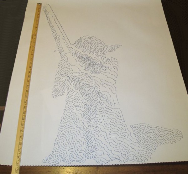
- WORKED: The single point of cord attachment. When I was using a crappy cardboard pen holder with cord attachment points very far apart, the entire pen holder would tip to one side or another when it got close to that side. This caused a bubble-like distortion effect towards the edges of the drawing. While this could be a cool effect to intentionally inflict on a drawing, it’s not what I was going for with that crappy cardboard design. Having the two cords meet at exactly the same point worked out incredibly well. Even when the robot was drawing the top left corner of Yoda’s lightsaber, the pen holder was always perfectly vertical.
- WORKED: Shape of pen holder flat side. The pen holder I’ve designed is roughly teardrop shaped, with a flat top. My thought with giving it a “flat top” was that it wouldn’t potentially develop a central raised point (between the circular top edge of the pen holder and the device I was using for the pen lift) when I was doing a pen lift. I figured that if I was using a “flat top” it was possible for the pen holder to be balanced on the edge of the flat top and the point of the servo arm – essentially turning my full contact pen holder into a three point contact pen holder with the servo arm as one of the points.
- DIDN’T WORK: Motor skipping? There is a large section in the middle of the drawing of Yoda, pictured above, that looks like it was shifted downwards slightly. This could have been because I was fussing a little with the robot while it was working. It could also have been because I was running the robot pretty fast (motor speed of 1600 when the normal is 600), because I had increased the acceleration (400 instead of the default 800), because I had the pots turned down too low (maybe, but the current settings have worked reasonably well for other drawings), because the pen holder was too heavy and causing too much strain on the motor (very unlikely since this holder is lighter than the cardboard abomination I was using) or some combination thereof. My guess is that I probably need to increase the pots when I increase the speed. It’s really unlikely that the pen holder itself was to blame for these missteps.2
- DIDN’T WORK: The pen lift. I haven’t drawn anything with a pen lift yet – but I did test the pen lift last night after Yoda was done. I noticed a few minor problems with the pen lift – but nothing to indicate I was on a completely wrong track.
- The first problem is that I glued the two batteries slightly too close to the clearance area for the micro servo arm. This is why the next version will include a holder for the AA batteries – to ensure they don’t get in the way.
- Second, even when fully extended the servo arm didn’t push out far enough to cause the pen tip to lift off the surface of the paper. This could be solved by either making sure the pen tip is positioned slightly farther back, extending the servo arm, or creating a servo arm powered cam, similar to Dan Royer’s Makeangelo (check out the video at about 4:35 for a view of the cam in action).
- Third, my concern is that since the micro servo is mounted in such a way that the servo arm sweeps from right to left, it could cause a similar sweeping motion to be applied to the pen tip – assuming I work out the pen tip depth issues. It’s possible that sweeping the arm upwards or downwards might minimize this effect. I just have no idea whether this is a valid concern or not – the servo arm might move so quickly that it’s not a real concern.
- Also, while not an actual issue, the servo motor cable applies a bit of weight to the pen holder. This will require me to reposition the cord attachment points – and may require me to add extra weights to the pen holder itself.
Once I change the pen position and maybe use a larger servo arm, I’ll try a vector drawing which requires pen lifts and re-evaluate this design. Overall, this design has basically worked beautifully. I’m looking forward to experimenting with some new variations on the design to see if I can eliminate the few remaining issues.
Default Series Title- I’ll pretend I was doing this for a system stress-test, but really I was impatient to get a big giant Yoda drawing [↩]
- Does that count as a pun? [↩]

