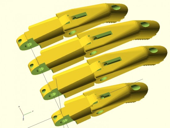
Parametric fingers – different lengths, same scale, with no distortion to hardware
I’m not ashamed to admit it – I’m proud of these parametric designs like few of my other designs. I’ve worked to make this design as customizable and organic as possible. The two modules that define each finger can be customized in two important ways – they can be lengthened1 as well as scaled up or down – without any distortion or change in the size of the holes for the hardware, elastic cords, or tension cords.
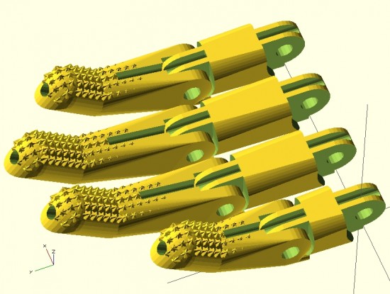
Parametric fingers – with grippy bits
Being able to lengthen2 the finger segments is important because it allows the user to create fingers of different lengths, as normal fingers are of different lengths, all without having to actually scale the fingers to different sizes and without causing a change in each finger’s diameter.
As I’ve discussed in earlier posts, being able to scale the parts up and down without distortion to the hardware holes is important because it allows users to use standard hardware throughout different designs.
For now, it’s back to work on the parametric palm to ensure a proper fit with these parts.
This post is intended as a set of “guidelines” to creating a parametric design in OpenSCAD.
Last Sunday afternoon was spent working out a parametric design for printable prosthetic fingers. Using the OpenSCAD function “hull” it’s relatively easy to crank out a nifty organic appearing design. Admittedly, you have to have a working knowledge the basic union/difference/intersection function first. However, once you do it’s really quite easy.
The feature of the design I’m most proud of is the “nail” part of the finger tip. I designed the “nail” by using the OpenSCAD function “intersection()” on two cylinders. The little “nubs”1 consist of a small cube, rotated so a corner is pointed straight up combined, with an identically situated cube rotated slightly.
When I’m designing something to be parametric, I usually don’t really start out designing it that way. I first strive to create a form in OpenSCAD that resembles closely the thing I wish to design. Then, I poke through the design code looking for those elements that are related to the design aspects I’m interested in changing based on parameters. Once located, I replace those parts of the design code with variables that can be specified when the module is called. I realize this is kind of a “high level” description of my design process for parametric things, but it’s still the best description.
Since last Sunday I’ve really done a lot with the design. Some simplifying and a lot of improvements. In the next post I’ll go over these features. I’m really excited to show these off. :)
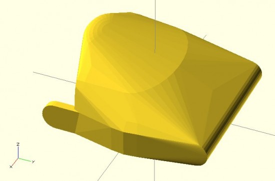
Above is my first attempt at designing a “solid” finger for the Cyborg Beast DIY printable prosthetic in OpenSCAD.1 The reason this is a “solid” finger is that I haven’t subtracted out any material to allow this partial finger to connect with anything else.
The problem with scaling (up or down) any design that requires fasteners and hardware is that when you do, the holes for the hardware are similarly scaled. This leads to more post-printing work drilling holes to widen them or to find larger fasteners that won’t rattle around in too-large holes.
Thus, if the hardware consists of 3mm screws, the holes for the hardware should be 3mm no matter how much the parts are scaled up or down. To make matters more interesting, not all holes in the model should be excepted from scaling. The above finger tip has a plastic end that is supposed to fit into a mid-finger piece – and those parts should be scaled up or down according to the size of the overall hand. Thus, some voids should be scaled2 and others not at all.3
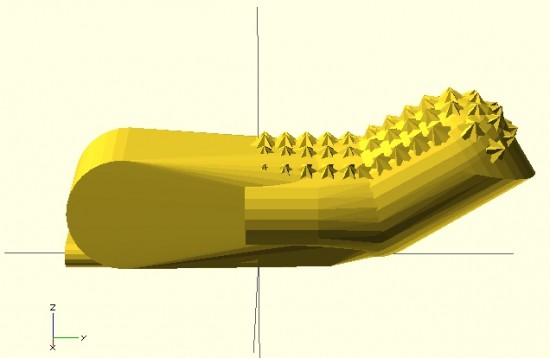
I’m rather happy with how this finger has turned out so far. It has most of what I understand to be the essential features of the Cyborg Beast fingertips, including little nubs along the finger pad to allow for gripping. I intend to make this an option, in case a user would rather use something like Plasti-Dip to make grippy finger pads, rather than relying on printed plastic bumps.
However, converting a decent design into a parametric design requires a little more work. The way I go about designing a parametric model is to first design one instance of the thing, in this case the finger tip. My next step is to poke through the OpenSCAD code to locate those aspects parts that contribute to the models’ essential features – length of the finger tip, for instance. Once I’ve found these bits, I then try to modify them so that I can insert different variables and arrive at sane variations on the model.
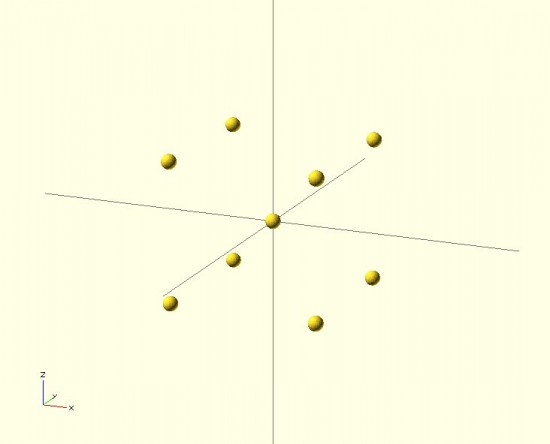
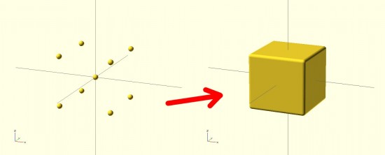
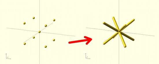
The result looks nothing like a jack! It looks more like a box with rounded edges. The limitation with the “hull()” command3 is that it connects all the outside points from the various shapes. The result is more like what the objects would look like if you covered them in plastic wrap – but not what they would look like if you tried to use shrink wrap.4 However, our goal is to get a jack. How should we go about this? The same way we eat an elephant.56 We need to use “hull()” multiple times7 to connect the central sphere to the eight surrounding spheres.
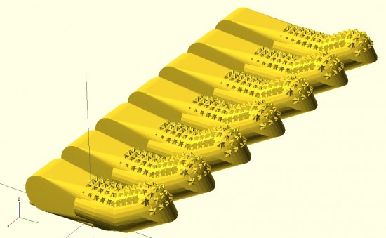
By breaking the overall design into pieces, you can use the “hull()” command to connect pieces of the design to one another in a seemingly organic fashion. Here’s a set of pictures of my most recent work that uses these design tricks.
I just fired up OpenSCAD, my 3D design program of choice, and then it occurred to me that it’s been quite a while since I’ve used it. A quick search for *.SCAD files on my hard drive revealed I haven’t updated any OpenSCAD documents since 5/13/2012. 1
That’s more than two months! How can this be?! I’ve got a pile of ideas stacking up.
How do you organize your ideas? I created an e-mail address for myself “ideas@DOMAIN.com,” jot down the ideas, and send them to myself constantly. If I have paper, I’ll sketch the idea out, take a picture, and e-mail the picture to this same address. I think I probably send myself about two or three e-mails a day.
I can’t wait to jump back into OpenSCAD and work on some of these ideas!!!
The Thingiverse page actually has a lot of information about the motor mounts. They’re designed in OpenSCAD and are mostly parametric. Since I’m mounting these motors inside a box, the mounts are designed to go into the corners of the box.
OpenSCAD Pirate Ship designed by MakerBlock, printed by BrazenArtifice
I can’t tell you how giddy I get when I see that someone has printed this and uploaded a picture. So, to the eight people who have done so – thank you!
I’ve printed this pirate ship twice and am reasonably satisfied with the result. The first I printed with support structure and the second without. I’m still getting used to Skeinforge v35, so I hope to get a better result. Interestingly, support isn’t really required for the bow!
One of things I really like about OpenSCAD is how anything I make in it is guaranteed to be manifold. It’s a solid modeler and by manipulating, adding, and subtracting solids – I should always end up with another solid. I exported two of the parts necessary for a Pez Powered Disc Shooter only to discover that OpenSCAD refused to compile one of the parts – because that part had some polygons with an incorrect winding order. Mind, I had no problems exporting the part in the first place – but importing it back? Nope.