Companion Robots and Maker Faire Season!

I’m super excited for Maker Faire Bay Area / Mare Island and Mini Maker Faire Rocklin.1  I’m not just excited to see everything, but to show all the things I’ve been working on for a while now.  It’s also time to pick up all the little dev boards I’ve somehow accumulated and see if I can make anything with them to show off.

  1. Project Boards
    1. Wemos D1 Mini.  A small insanely cheap (~$3?!) WiFi enabled dev board2 , which has 4MB onboard and can run Arduino.  I think it can also run MicroPython, but I haven’t tested this yet.
    2. Wemos 600 Pico.  An even smaller, even cheaper (~$2 when ordered from China) WiFi enabled dev board that runs… MicroPython?  I think??  I’m saying “I think” because I haven’t been able to get it to do anything yet.
      1. Since starting this blog post, I found a guide on installing MicroPython on Wemos boards that seems promising.
        1. Flashing MicroPython on an ESP8266
        2. https://github.com/espressif/esptool/tree/master
        3. Arguing with Python to let me use “esptool.py”
          1. esptool -p COM13 -c esp8266 flash_id
      2. As promising as that series of blog posts looked, I eventually scrapped the Wemos because it was just too much of a pain to get going with MicroPython.  I think I could have made it work, but for $7 I could also just use the Adafruit QtPy I already have.  The advantages of simply uploading code over a USB cable into a virtual drive just can’t be overstated.
    3. Other Boards
      1. I have a bad habit of picking up dev boards.  I’ve got several Adafruit QtPy’s, several Adafruit Trinkets, an Adafruit FX Sound Board, Raspberry Pi Pico (non-WiFi), various Digispark boards, a small handful of ATTiny85’s, and an even weirder assortment of VERY small programmable circuit boards (ISD1806B-COB) designed to go in greeting cards (just 6 seconds), etc.
  2. Companion Robot
    1. Background.
      1. I started this post at least a month ago when I only had a vague idea of what I wanted to make and even fewer skills.  After seeing my kid’s companion robot take shape, I wanted to get in on the action and make my own.  I decided to make a really small companion robot with just some LED’s, piezo, and small microcontroller unit.  I’d taken a stab at making a companion robot a few years ago, but set it aside for a variety of reasons and never went back.
      2. The idea for this new robot would be something a little less ambitious, make more use of NeoPixels than in prior projects3, with a little more interactivity, trying out some CircuitPython, and… let’s be real… more pizzazz!
    2. Idea:  Friendly Cloud/Vapor/Flame
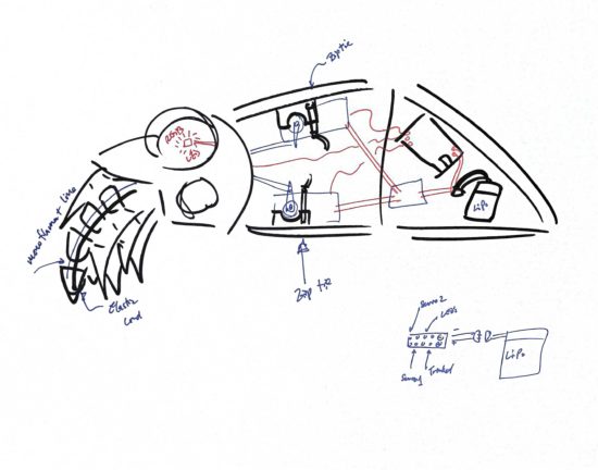
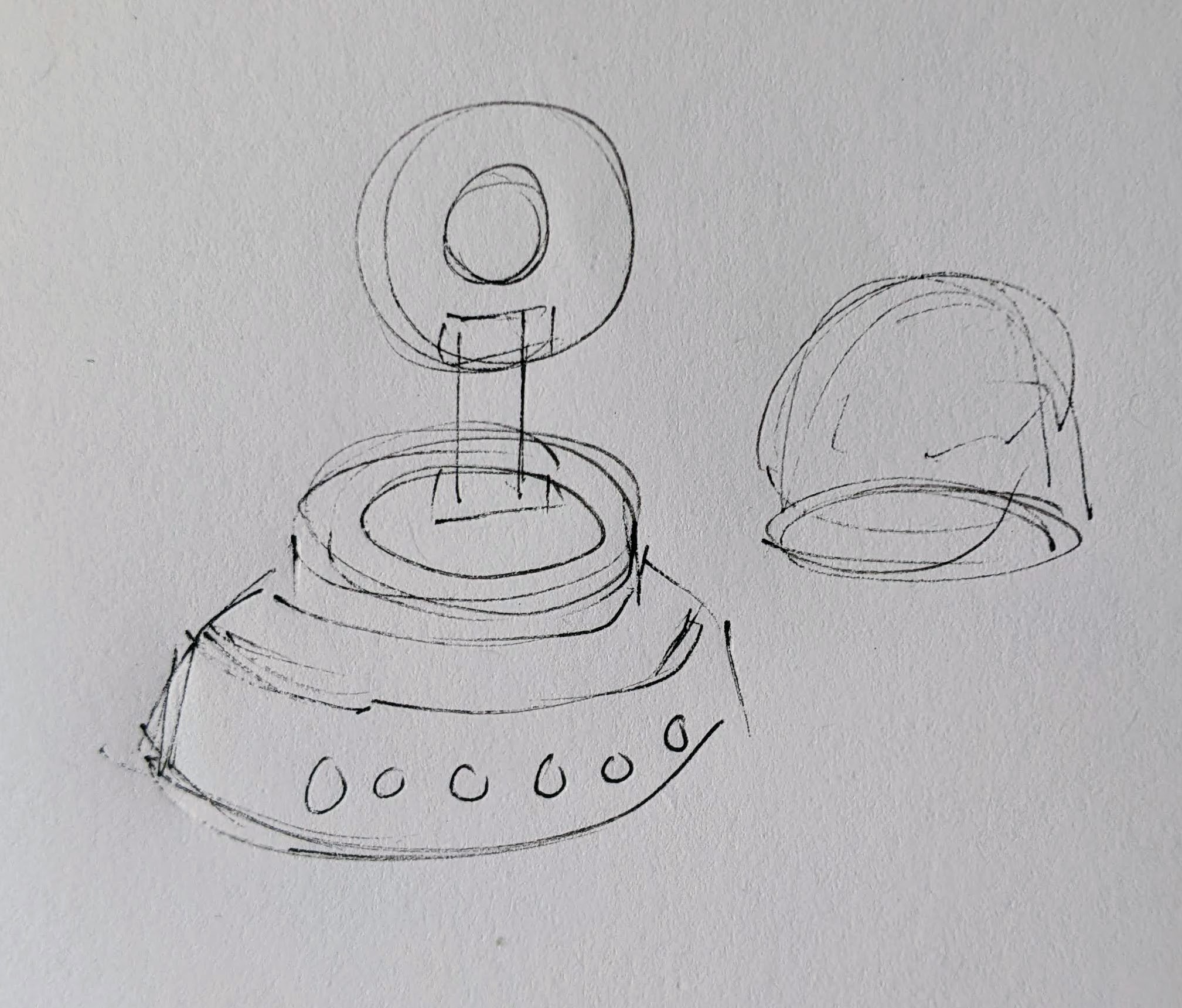
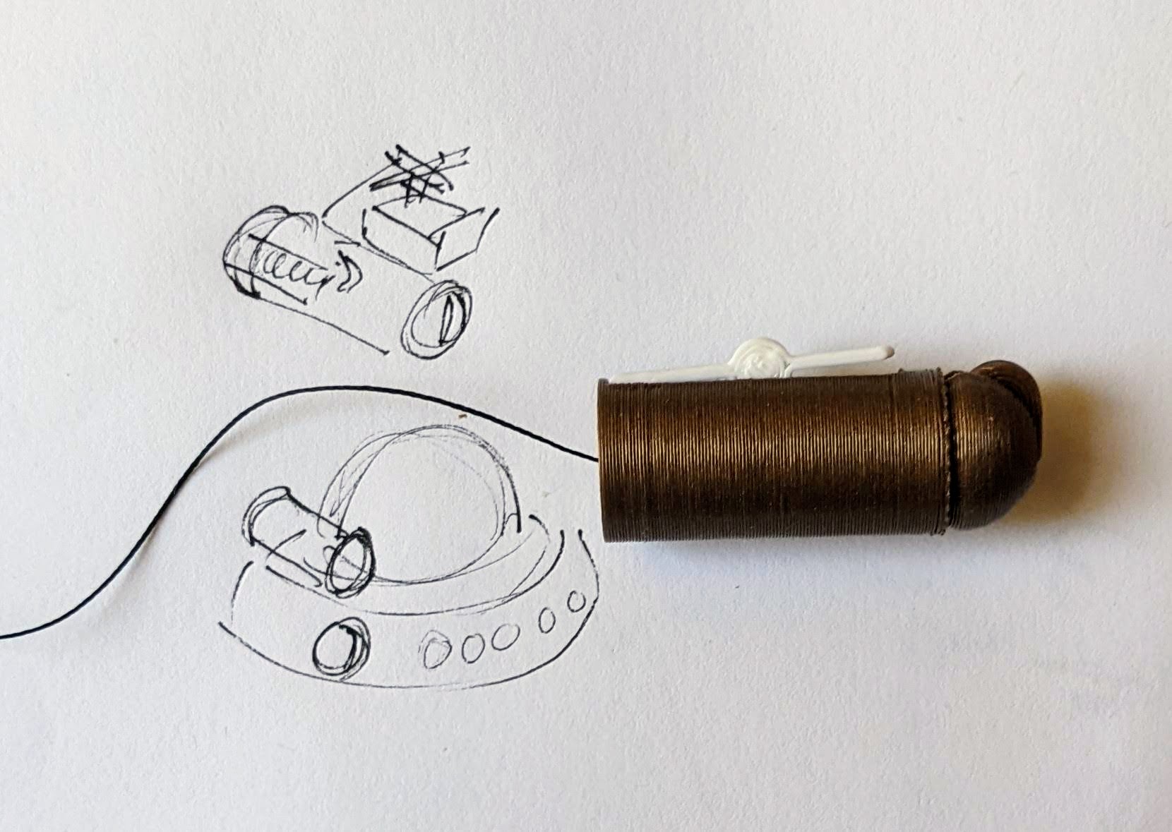
      1. I still really like the copper-toned PLA I’ve been using since it has something of a steampunk flair to it.  I settled on repurposing a small plastic enclosure with a clear dome as the “body” for the robot.  I wanted it to look something like a small entrapped / captive / domesticated4 sentient cloud of vapor or perhaps flame held within a steampunk enclosure.
      2. As a very small, inexpensive board that could run either Arduino or CircuitPython, I decided on the Adafruit QtPy M0.  It could run NeoPixels, there were lots of cool guides on it, plenty of pinouts, and could definitely fit within the confines of my enclosure.
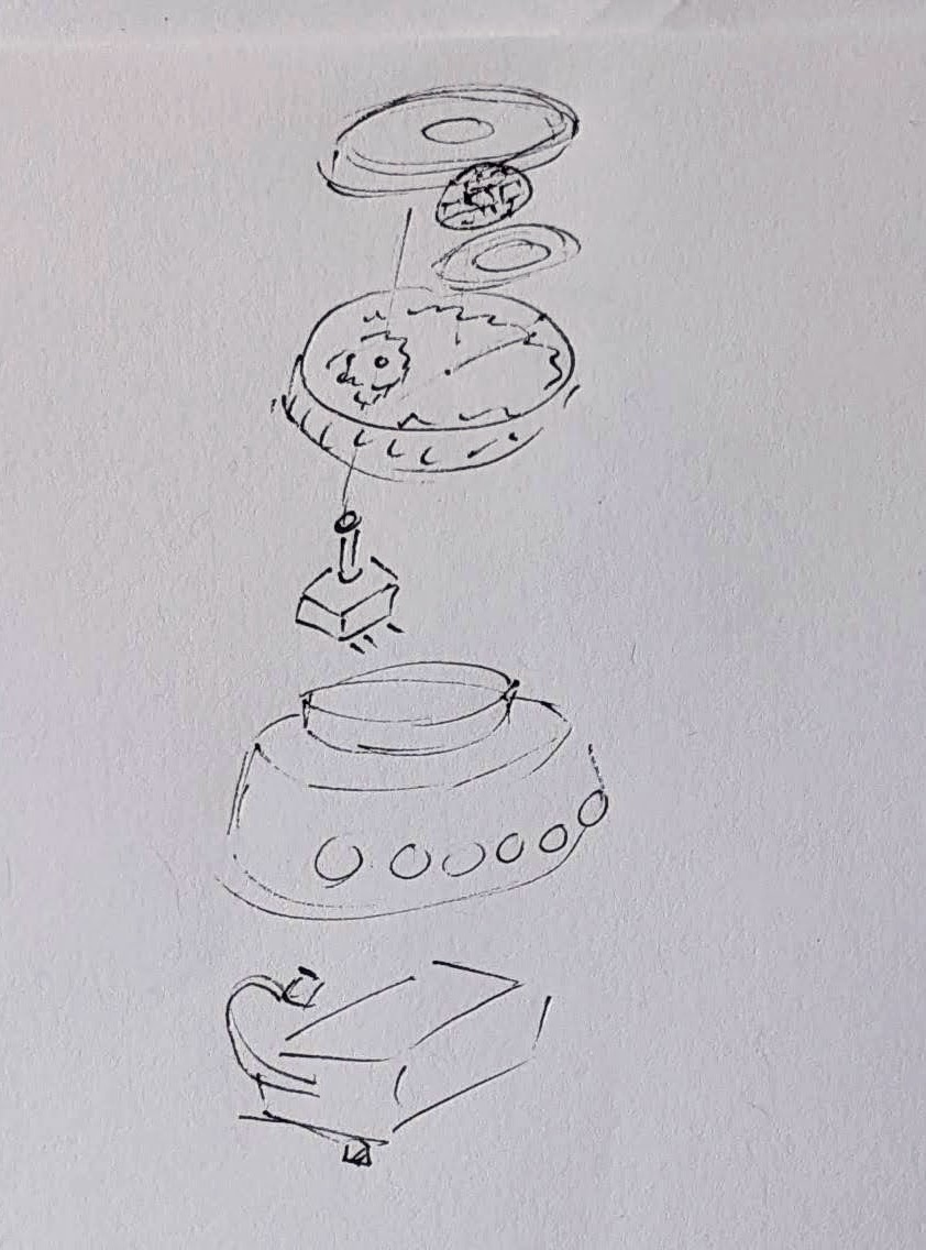
    3. Enclosure:
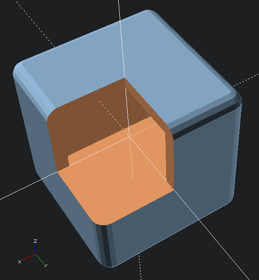
      1. I started the enclosure by trying to design and 3D print a part to mate with the clear plastic dome.  It took a few tries.

        This slideshow requires JavaScript.

      2. Once I had that, I extended the base so it could hold more electronics.  I could definitely have shoehorned everything into the dome, especially if I took up some of the space inside the dome, but even with an “elevated base” it was still plenty small and could use a battery pack rather than a rechargeable lipo.
      3. Once I had a good design for the enclosure, I tried to make it work with an existing 3xAAA battery pack.  In the process I yanked off the connector and ended up soldering the battery pack leads directly into the circuits.
    4. Internal Electronics
      1. I’m just not a great electrical engineer and am still copy/pasting from various guides, tinkering, changing bits of code, swapping out parts, and using “close enough” resistors.  Wiring up some LEDs or a piezo to a project isn’t very difficult – it’s some of the more fiddly bits.
      2. Piezo Element Speaker
        1. I wanted to use a piezo buzzer/speaker because they’re large and incredibly thin.  They’re not without their downsides.  The crystal wafer is also thin and a little fragile.  The piezo buzzer without additional electronics has the potential to act as a knock sensor and can generate a high voltage spike which can fry a board.  And, without additional electronics, the piezo just isn’t very loud.  There are some libraries for the Arduino that basically double the volume of a piezo by connecting it to two pins and then running each opposite of the other, doubling the voltage difference, but they only work for Arduino chips.5
        2. After searching for various ways to increase the sound of the piezo elements, I settled on trying to use the Adafruit piezo amp.  I bought two – and tried desoldering the terminal blocks.  This completely ruined one.  The other one worked great, but for the modest volume gain it was just too big in an already cramped enclosure.
        3. After searching around, I found some amplifier circuits using a small number of common parts.6
        4. Then I tried building an amplifier circuit using an NPN transistor.  After reviewing the datasheets for my NPN transistors (and PNP transistors), and breadboarding the circuit with resistors, I sketched it a few times, laid it down with copper tape, soldered it in place with SMD resistors, then pulled it off and placed it onto a piece of Kapton tape and put another piece on top – “laminating” it in place.
      3. Capacitive Touch
        1. Buttons are great and all, but with a capacitive touch pad, I could add metallic elements to my robot rather than a much bulkier button.  I bought a few brass upholstery tacks because they looked great – but they just would not accept molten solder.  I ended up cutting the prongs short with wire cutters, wrapping the stub with copper tape, then soldering the wires to the tape.  I’d also added a little piece of heat shrink tubing over the connection to help keep it together.  It’s been working well so far.
      4. LED Animations
        1. As we know from Phillip Burgess‘ incredible “power sipping NeoPixel” guide, we can conserve power and increase the impact of the LED’s by reducing the number of LED’s, keeping max brightness ~20% for a disproportionately large impact, running fewer LED’s at a time, and even running fewer colors at a time.  Between Phillip’s work, Todbot’s guide, and the specialized QtPy NeoPixel guide by Kattni Rembor, I was able to put together a few neat animations.
      5. Piezo Sounds
        1. I had a heck of time getting the piezo buzzer to do anything interesting.  Fortunately, with my kid helped convert the piano music for “Paint It Black” into tones for me.  I haven’t gotten all the note timings right, but I’m working on it!
  3. Future Modifications
    1. More Accessible Enclosure.  Right now the “lid” with a hole for the LED ring just sits on the enclosure with a light friction fit.  One idea is a hinged lid, either with a conventional hinge or perhaps a hidden swivel hinge.  The problem with that, of course, is it requires even more internal space.  Other ideas include a ring on top that screws down, holding the top down and in place.  I’m crap at designing screw threads, so I’ve avoided this.

      Hinged lid for enclosure
      Hinged lid for enclosure
    2. Piezo Knocks.  Perhaps the next version will include some kind of tap / double tap / knock sensors using one or more piezo elements.
    3. Knobs.  There’s not a ton of room inside the enclosure, but by including a gear within a gear, I might be able to rotate part of the case and have it manipulate a potentiometer.

      Offset gear within gear, manipulating an off-center internal potentiometer
      Offset gear within gear, manipulating an off-center internal potentiometer
    4. Motors.  A robot that just flashes lights and makes a few beeps can still be pretty interesting.  However, I have some neat potential features that could be added with just one or two motors.  There are some interesting limitations with the current incarnation of this robot and using a QtPy.  I’ve only got 10 pinouts7 , 1 for NeoPixels, 1 for the piezo, 6 in use for the capacitive touch sensors, leaving 2 for other potential tasks.8  However, space is already tight so one or two micro servos would be a big space commitment.  I’ve seen some really tiny micro servos that might work, but I have no idea where to source them.  One silly idea is a “weapons system” using a spring loaded projectile activated by a very small servo.

      A small spring loaded projectile launcher, actuated by a small servo
      A small spring loaded projectile launcher, actuated by a small servo
    5. Creating Tone Library.  The basic piezo tones are easy enough to play, but including the entire list of tones and the frequencies associated with them seems eat up the poor little QtPy’s memory.  I think compressing them into a library might be the way around this issue.
    6. Playing WAV files.  WAV files are bulky, but that’s the only sound file format a QtPy M0 can play.  However, with the extra 2MB from the SPI chip installed, this shouldn’t be a huge problem.  I used Audacity to mix the sound clip down to mono then to 22 KHz sample rate.  My preliminary tests worked – but it was incredibly quiet.  I haven’t run it through the audio amplifier yet, but I’m planning to.
    7. Sleep / Deep Sleep.  Ever since I swapped out the tiny LiPo for a 3xAAA battery pack, I’ve had a lot more battery life, so adding sleep / deep sleep functions haven’t been a priority.  However, this inclusion just couldn’t hurt.
  4. Other QtPy and CircuitPython Resources
    1. Adafruit’s QtPy CircuitPython PWM resource
    2. TodBot’s CircuitPython tricks
Companion Robots: Building Robot Friends
  1. Cephalopod Robot Friend, the story so far
  2. Cephalopod Robot Friend Progress
  3. CuttleBot Body and OpenSCAD Design Tips
  4. An Assembled CuttleBot Body
  5. Building the Monocle Top Hat Cat for #MicrobitVirtualConcert
  6. Companion Robots and Maker Faire Season!
  1. I just got a notice they’re no longer a “Mini”! []
  2. pinouts for my future reference []
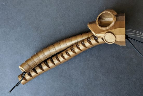
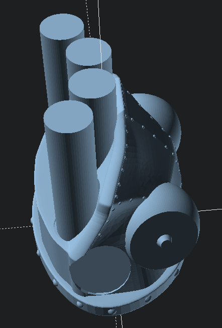
  3. LED goggles and a Marvel Universe inspired set of “Infinity Knuckles” []
  4. OMG dome-sticated?! []
  5. This is just my very basic understanding of how it works.  I’m entirely positive this is far too simplified. []
  6. And one very long article about using a lot of parts []
  7. 12 if you want to count the onboard NeoPixel []
  8. Or 4… []

Building the Monocle Top Hat Cat for #MicrobitVirtualConcert

This slideshow requires JavaScript.

The last few months there have been some pretty amazing little robots posted online for the Tinkering Studio / Exploratorium #MicrobitVirtualConcert.  I wanted to make something and participate and my 6 year old was interested in helping out.  I don’t have a Micro:Bit, but I’ve got a few other microcontrollers and the Adafruit Circuitplayground Express is perfect for this kind of project.

Here was our basic process:

  1. Brainstorm ideas
  2. I eat a frozen pizza and save the cardboard
  3. Sketch of robot – and what it should do
  4. Taping sketch of robot over white cardboard
  5. Tracing sketch with a pencil with enough pressure to leave an indentation
  6. Coloring robot
  7. Measuring / designing a 3D printed plastic part to fit the servo (before I committed more plastic to it)
  8. Scratching my head and jamming together circuitpython code for servos and musical notes together.  I had really wanted to also have the eyes light up with Neopixels too, but…
  9. Ultimately, I had a sketch for lights + musical tones and another for servo + musical tones.  My daughter made the executive decision to go with servo + musical tones. 1
  10. Revising the design to include some “wings” for more surface area to glue to the card board and increase stability
  11. Adding extra “wings” so that the popsicle sticks could pivot on a piece of paperclip in the plastic holder, rather than in the cardboard
  12. “Drilling” holes in the popsicle sticks with drill bits rotated by hand
  13. Gluing in servo holder and just lashing bits of things together in the back with hot glue, blue tape, and some wire
  14. Testing different kinds of tails before gluing the final version in place
  15. The code and STL’s aren’t anything amazing and I didn’t do a lot to comment them.  However, if you might find them useful, I’ve uploaded them to PrusaPrinters.

Here’s the final robot in action:

Companion Robots: Building Robot Friends
  1. Cephalopod Robot Friend, the story so far
  2. Cephalopod Robot Friend Progress
  3. CuttleBot Body and OpenSCAD Design Tips
  4. An Assembled CuttleBot Body
  5. Building the Monocle Top Hat Cat for #MicrobitVirtualConcert
  6. Companion Robots and Maker Faire Season!
  1. What can I say?  In order to bring her onto the project, I had to agree to give her final cut. []

An Assembled CuttleBot Body

This slideshow requires JavaScript.

It’s one thing to hack away in CAD software, rendering the idea of a model.  It’s another thing entirely to pull it off the print bed and pop it all together.

This slideshow requires JavaScript.

Last night before going to sleep I started the 2+ hour print job that became the center body piece for the CuttleBot.  When I woke up in the middle of the night, I plucked it off the build platform, started the tail section printing (a 90 minute print job), and passed out again.  This morning I printed 15 connector pins while getting ready for work.

Just before leaving for work, I yanked out the support structures using some needle nose pliers and popped it all together with the connector pins, and took some pictures to share with you, dear reader.

This was an incredibly satisfying result.  Sometimes the work spent on something like the little pins and sockets feels so removed from the design of the main object – so very far from the goals.  It feels similar to the work that goes into painting a house – you spend all this time NOT painting before you actually paint.  Moving and covering furniture and decorations, taping and masking areas off, removing cabinets and doors.  But, as long as I was able to keep my eye on the vision of the final model, laying that ground work on these components meant that I really could assemble a foot long plastic CuttleBot body in a few seconds.

Sigh.  At this point, it kinda resembles a CyberMat more than a robotic cuttle fish.

I enjoy sketching out my ideas, so here’s one in case you like looking at them.

It’s NOT a CyberMat! It’s a robotic cuttlefish!

So, what’s left to do?  A whole lot.  I need to:

  1. Design newer, thinner tentacles, so I can fit more into the CuttleBot’s head.
  2. Hollow out the robot’s head or at least create channels for wiring for LED’s inside the eyes.
  3. There needs to be some mounting areas inside the robot to secure one or two micro servo motors, a small circuit board, a battery, and possibly a few additional components.
  4. Possibly create a door allow easy access to the interior of the robot.  Once I start adding electronics, it might be great to have an on/off switch and nice to be able to connect a USB cable to it to recharge an internal battery or reprogram the behavior.
  5. Add the electronics and program them.
    1. This is probably two servos, several chained NeoPixel LED’s, a LiPo battery, an Adafruit Trinket, and possibly a LiPo charger (if I have one lying around).
    2. If I’m already working towards building a new version anyhow, I might want to drop a few dollars on an OSHPark Board to help make the power from the LiPo easier to route to the servos, LED’s, and board.

However, I don’t think I’m going to be able to finish the robot before Friday.

I think I could probably manage blinking LED eyes by Friday.

Maybe.

Companion Robots: Building Robot Friends
  1. Cephalopod Robot Friend, the story so far
  2. Cephalopod Robot Friend Progress
  3. CuttleBot Body and OpenSCAD Design Tips
  4. An Assembled CuttleBot Body
  5. Building the Monocle Top Hat Cat for #MicrobitVirtualConcert
  6. Companion Robots and Maker Faire Season!

CuttleBot Body and OpenSCAD Design Tips

This slideshow requires JavaScript.

I really like 3D printing – but really dislike post-processing.  This means I’ll make extra efforts to design things that can just be plucked off the build platform and hand assembled without tools.  With my limited build volume, this also means larger objects need to be printed in sections.

I’m very proud of a particular design method in the CuttleBot.  I designed the organic and non-angular design of the CuttleBot body by using the “hull” function and several carefully deformed and positioned spheres.  However, it would be very difficult to hollow out the interior – since it would mean designing another entire structure to be subtracted out.  Instead of creating the outside shape I wanted and using difference to hollow the interior, I designed the interior shape and used that to create the exterior with the “minkowski” function.

Here’s an OpenSCAD code example:

difference()
    {
    //  Traces sphere around exterior of cube
    minkowski()
        {
        //  Main object
        cube(50, center=true);
        //  Object to trace around main object
        sphere(r=5);
        }
    //  Removing center of object
    cube(50, center=true);
    // Arbitrarily large cutout
    cube(10000, center=false);
    }
Minkowski sample
Minkowski sample

Although, now that I think about it, there’s probably an even cooler way to do this!  Since the above code needs to refer to the “target” object twice, that code can be simplified by using the “children” function.  The below code creates an identical shape.

hollowObject(5) cube(50, center=true);

module hollowObject(thickness)
    {
    difference()
        {
        minkowski()
            {
            children();
            sphere(r=thickness);
            }
        children();
        //  Arbitrarily large cutout
        cube(10000, center=false);
        }
    }

The great thing about a modeling process like this is it allows  you to maintain an even thickness all the way around the model.  This would be increasingly difficult as the complexity of the underlying model increases.

Lastly, to return to the model, after hollowing out the interior of the CuttleBot, I added areas for the pins to connect the sections together.  The body of the robot is in three sections – the head, the mid-body, and the tail sections.

There’s still more to do on the model.  Ideally, I’d create a way to open the robot without having to completely take it apart each time.  A hinged door would work fine.  Also, I should probably add an area where one or more micro servos could be zip-tied or otherwise secured in place.  Also, I’ll need to modify the robot’s head later on to allow for multiple (smaller) tentacles and channels for adding wiring for LED’s to the eyes.

There’s also the whole “adding electronics” thing.  You know, to make this less a puppet and more a robot.

Companion Robots: Building Robot Friends
  1. Cephalopod Robot Friend, the story so far
  2. Cephalopod Robot Friend Progress
  3. CuttleBot Body and OpenSCAD Design Tips
  4. An Assembled CuttleBot Body
  5. Building the Monocle Top Hat Cat for #MicrobitVirtualConcert
  6. Companion Robots and Maker Faire Season!

Cephalopod Robot Friend Progress

Well, it’s here!  Today is the start of #CephalopodWeek on ScienceFriday!  There’s a little progress to report on my, tentatively named, CuttleBot.  I’ll post a picture first, then get to describing the progress so far.

Assembled CuttleBot head, side view

In the prior post I listed some of my sources of inspiration.  Another such source is the work of Sean Charlesworth and his awesome Octopod, Gowanus Monster, and newly published Scuttleship.   ((If you like his work, be sure and check out his Etsy shop!))

This slideshow requires JavaScript.

Since I need special connectors for the articulated/articulating tentacles and I wasn’t able to edit the files in OpenSCAD, I wasn’t able to use Sean’s STL files.  However, I really like the aesthetic of his designs1 and how they really evoke the form of an octopus or cuttlefish.  Here’s a mock up I used to help me visualize what a full-scale Scuttlefish head might look like with the tentacles I designed.

Scuttlefish with placeholders for tentacles

Unfortunately, the Scuttlefish head and body parts are just a tad too large for my small printer’s build volume.  However, even if I were using a larger printer, I would still not want such a large robot as I’m hoping for this to be a shoulder-mounted companion.

Thus, I began work creating an OpenSCAD cephalopod cuttlefish head inspired by Sean’s work.

This slideshow requires JavaScript.

Now that I had a design, I set the printer to work over night.  This design is mostly to see if the various parts for the tentacles would work with this head.  Since I want to put some LED’s in the eyes and possibly the mouth, I’ll need to hollow it out later.

The print took a little over an hour for the head.

This slideshow requires JavaScript.

How about a video of it working?

I’m very happy with the progress so far.  If I can shrink down the tentacle mechanisms, I can add more tentacles for more interesting emoting and animations.  The video just shows the results of me yanking the fishing line running through the CuttleBot’s head.

Here’s a few more sketches of how I am planning on putting it all together.

This slideshow requires JavaScript.

I might add some fabric frills / fins, instead of printed ones.  I was also contemplating letting the top “shell” of the CuttleBot be formed from 3D printed spines with a fabric or thin plastic sheeting covering.  This might help reduce weight or allow for internal lights to shine through the body.

Companion Robots: Building Robot Friends
  1. Cephalopod Robot Friend, the story so far
  2. Cephalopod Robot Friend Progress
  3. CuttleBot Body and OpenSCAD Design Tips
  4. An Assembled CuttleBot Body
  5. Building the Monocle Top Hat Cat for #MicrobitVirtualConcert
  6. Companion Robots and Maker Faire Season!
  1. Cephalopod Steampunk?! []

Cephalopod Robot Friend, the story so far

Quick lead in:  I am trying to build a cephalopod robot shoulder friend.

I was disappointed that I only learned of Glow Ascii‘s owl robot companion, Archimedes, after Maker Faire Bay Area 2018.  Over the year, leading up to Maker Faire Bay Area 2019, I followed Odd_Jayy‘s spider/bowler Anansi robot companion with similar rapt interest.

Still high off Maker Faire 20191 , I was also excited by the prospect of #CephalopodWeek on NPR’s ScienceFriday.  Between cuttlefish, squid, and various octopuses (especially the “Opisthoteuthis Adorabilis“), there are a LOT of awesome little friends to consider making.

While trying to avoid work, I posted a sketches to Twitter.

This slideshow requires JavaScript.

Last week I started designing a few parts, drawing from some experience designing printable prosthetics for the E-nable project a few years ago.  I was trying to build it out of what I had on hand, which did not include elastic cord.  I thought a zip tie might provide enough “spring” and “give” to work.

This slideshow requires JavaScript.

I admit, this was a total mess.  I suppose it is only fitting I use this meme featuring Dr. Zoidberg.

Thanks Dr. Z
Thanks Dr. Z

Thanks to some kind encouragement from Odd_Jayy, I kept moving forward.  Rather than focusing on the end of the tentacle, I got to work on the basics of the mechanics – channels for the elastic cord and fishing line, wedges cut into the faces so the tentacle could articulate.

This slideshow requires JavaScript.

The tabs on these parts were too thin and tended to break when I assembled them.  However, the next version worked really well.

This slideshow requires JavaScript.

These worked a lot better, so I started cranking out parts.

The nice thing about these tentacles is that they look somewhat lifelike without actually requiring much in the way of electronics.  As long as I can design a body/housing and put a servo inside, that one servo could possibly pull on 8 different sets of fishing line to articulate all the tentacles at the same time.  And, since it’s just fishing line, there’s no special routing of brake cables necessary.

The tentacles are somewhat larger than I would like, so that means where they connect to the body needs to be similarly large.  There’s definitely room for improving the tentacle segments.  I’ve already designed two different “ends” for the tentacles, so they’re rounded instead of exposed connectors, fishing line, and elastic cord.  Also, to make the curling tentacle look better, I should angle the the top and bottom of each segment.  Another improvement would be to rotate the articulation angle for different segments to give the tentacle a more organic look when moving.

However, if I don’t get working on the body of the robot, it’s not going to ever get done.  Given the size of the tentacles, I’d need to have them all on one side, lest the little robot take over my entire shoulder.  Here are some “Cuttle-Bot” sketches along with a robot body design.  If you look at the design, you’ll notice the connectors are rotated to different angles.  This is so that the tentacles would each spring back together towards each other – and then splay outwards when articulated.

This slideshow requires JavaScript.

However, this last design takes FOREVER2 to render in OpenSCAD.  This is at least partially due to design and code inefficiencies, but also due to the number of spherical parts, facets, and “hull” operations needed to make these parts work.

I think I may want to try shrinking the tentacles slightly so I can build a smaller-bodied robot.  Either way, I have to get cracking on at least some kind of housing/body and mounting motors/electronics before I can keep moving forward.

Companion Robots: Building Robot Friends
  1. Cephalopod Robot Friend, the story so far
  2. Cephalopod Robot Friend Progress
  3. CuttleBot Body and OpenSCAD Design Tips
  4. An Assembled CuttleBot Body
  5. Building the Monocle Top Hat Cat for #MicrobitVirtualConcert
  6. Companion Robots and Maker Faire Season!
  1. LONG LIVE MAKER FAIRE! []
  2. Well, a little over 5 minutes []