Thanks to @raster, I’m going to do a side-by-side taste test of several different flavors of OpenSCAD.1 To give each one a similar test, I’m trying out my D-Pad design from … uh, earlier this morning.2
Obviously, the good folks working on OpenSCAD have dramatically improved preview/render times over the last four years. The speed boost in using a later snapshot is pretty significant if you’re doing any kind of complex designs. They must be using some kind of cache system to make the render times so fast.
The speed differential between 2024.01.13 and the latest snapshot is so slight, I’m not going to switch things up unless I bump into a design that struggles with rendering some complex feature.
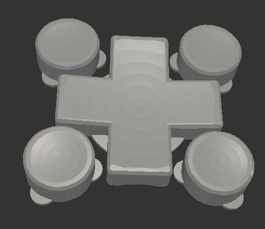
This week’s topic related to @deshipu’s directional keypad designs. The directional pad is clearly the most complicated part of the design. The four buttons are basically just cylinders that can be created in several different ways.
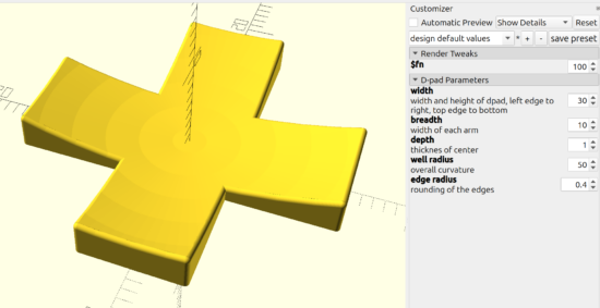
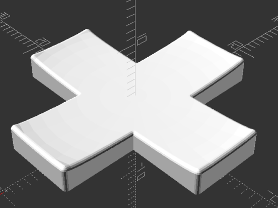
After staring at the design a little longer, I changed from my original design idea to creating a 2D cross, extruding that, subtracting out the curved area described by a sphere (a homebrew hack I’ll describe below), using the minkowski function to surround the entire surface with a small sphere to give it a rounded look, then cutting the bottom off to ensure it is flat. I didn’t include a flat cylinder as in the original design above, but that’s a trivial addition. The downside? This is a 5 minute render on my machine, largely due to the minkowski function.
You’ll notice I use “offset” to reduce the size of the directional pad, because I knew I was going to round it all with the minkowski function in a few lines.
The directional pad is actually just a rectangle, run through a for loop once to rotated it by 90 degrees, before being extruded to the specified height.
The last two lines of code are used to create a large cylinder, larger than what I knew the pad would be, then mirrored in the Z axis to cut everything below the XY plane.
As in prior designs, I pre-define “fn” to be a “pow(2,5)” so that I can use a low exponent to iterate designs quickly, then crank it up for a detailed design.
The hack I use the most often here, and the one I’m the most proud of, is where I make a sphere like “sphere(r=0.5)” and then scale it by whatever I need. Since the sphere has a diameter of “0.5” mm, the actual sphere is 1mm in diameter – so when I scale it in the XY by 30 and in the Z by 2 (since the edges of the keypad are 3mm tall and the center is 1mm tall), the diameter is now 30mm and the height is 2mm. This little trick, of being able to scale a sphere to the exact size I need has come in handy countless times.
I’m not the best programmer, not the best at OpenSCAD, but I’m kinda happy that I was able to build this in about 31 lines of code. :)
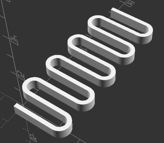
“I’m trying to come up with a good way of creating this in OpenSCAD… I have something using a bunch of hull’d cylinders but I’m wondering if there is a better/easier way to do it.” @rasterweb
A friend posted a design pondering whether there was a better way to design an object in OpenSCAD. As so often happens when I approach a 3D design, one solution pops up in my head… and is immediately discarded as garbage. That first thought was to create a negative of the interior of the spring, then iterate along the length of a stretched cube.
In the end, I opted for1 creating a flat version of a single “loop”, made from differenced hulled circles, repeated over the number of desired loops, then trimming alternating ends (so it wouldn’t look like a chain).
I like to use OD/ID/OR/IR to mean outer diameter, inner diameter, outer radius, inner radius.
I think the “spring_loop” module could be simplified slightly by calling another module which creates each hulled circle, but weighing the additional module code against just retyping a little code I opted for what got it done faster.
I like to specify the facets on circular objects right at the top of the file. This way, I can adjust the smoothness of the object by just changing just the exponent part of the $fn system variable.
Reasonably parametric. There’s some additional further optimization that could be done in the spring alternate end clipping.
Can’t wait to see what @rasterweb makes with a 3D printed spring!
[Yep. This was the whole blog post. I don’t know what happened to that set of parts, if I sold them, gave them away, or what. I hope I gave them away.]
[Holy cow. Can you imagine a time when a person could singlehandedly have made a comprehensive list of all open source 3D printers in an afternoon?]
Here’s a list of all of the RepRap, RepStrap, and MakerBot open source 3d plastic FDM 3d printers I can find. When possible I’ve tried to link to the official site, helpful derivative sites, instructions, and parts. I’ve also included some notes.
RepRap – The ultimate in DIY personal fabrication technology. Source everything yourself and put it together!
Dialing in Skeinforge settings and calibrating a MakerBot can be a frustrating and time consuming process. I’m always tempted to just start tweaking settings and start printing. Part of the reason I’m impatient is that making a change to Skeinforge, printing a test, noting observations, and LRR1 is SOOOOoooo incredibly boring next to the magic of watching things materialize inside a MakerBot.
Now, I don’t want to it sound like I’m down on Skeinforge. It’s an incredible piece of software that does some amazing things. However, the dozens of identically sounding settings put me in the mind set of deer and headlights.
or this post could be titled … “Open source intern tells all!”1
A review of the MakerBot Industries Cupcake CNC today from a former MakerBot intern discusses the MakerBot’s use as a tool. Some of the comments bring to suggest its usage as an expensive toy. I’ve used my MakerBot as a tool to print tools and as a tool to print toys. I suppose at the point I’m using it to print up toys I’m really using as a toy.
I’m fairly confident my MakerBot will pay for itself. That’s not a claim most people can make about their toys. I have printed replacement parts for toys, broken parts around the house, and broken tools – thereby saving me those replacement costs. This probably doesn’t amount to more than $20 or so. That’s not a great return on an investment, but it is returning
[That’s it. Just the title. I have no idea what this piece may have been, how much I was paid, or how long it took! I was just excited that my little 3D printer was making a little bit of money and started to share it with the world… before sitting in my drafts folder for … more than 15 years]
There really is something special about having built this robot for myself. I know it pretty well how it works and why certain design and engineering decisions were made.
I’ve also modified and customized this robot as I’ve used it. I’ve moved the extruder board, rotated the motherboard to give me better access to the SD card, drilled a few holes in the sides, yanked out the opto-endstops, extended the wires running to the extruder motor, thermistor, and nichrome. I’ve even designed a few minor printable upgrades.
When my extruder stopped working (twice) I just took it apart. I know I’m not going to break it as I do so. And, hell, if I do break it I’ll just fix it.