An Assembled CuttleBot Body

This slideshow requires JavaScript.

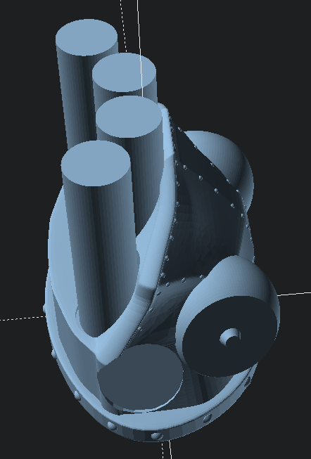
It’s one thing to hack away in CAD software, rendering the idea of a model.  It’s another thing entirely to pull it off the print bed and pop it all together.

This slideshow requires JavaScript.

Last night before going to sleep I started the 2+ hour print job that became the center body piece for the CuttleBot.  When I woke up in the middle of the night, I plucked it off the build platform, started the tail section printing (a 90 minute print job), and passed out again.  This morning I printed 15 connector pins while getting ready for work.

Just before leaving for work, I yanked out the support structures using some needle nose pliers and popped it all together with the connector pins, and took some pictures to share with you, dear reader.

This was an incredibly satisfying result.  Sometimes the work spent on something like the little pins and sockets feels so removed from the design of the main object – so very far from the goals.  It feels similar to the work that goes into painting a house – you spend all this time NOT painting before you actually paint.  Moving and covering furniture and decorations, taping and masking areas off, removing cabinets and doors.  But, as long as I was able to keep my eye on the vision of the final model, laying that ground work on these components meant that I really could assemble a foot long plastic CuttleBot body in a few seconds.

Sigh.  At this point, it kinda resembles a CyberMat more than a robotic cuttle fish.

I enjoy sketching out my ideas, so here’s one in case you like looking at them.
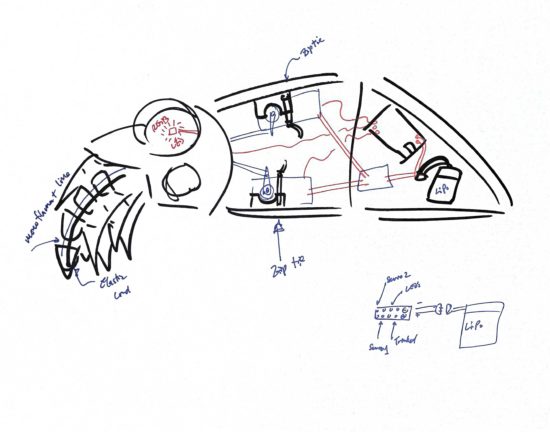
It’s NOT a CyberMat! It’s a robotic cuttlefish!

So, what’s left to do?  A whole lot.  I need to:

  1. Design newer, thinner tentacles, so I can fit more into the CuttleBot’s head.
  2. Hollow out the robot’s head or at least create channels for wiring for LED’s inside the eyes.
  3. There needs to be some mounting areas inside the robot to secure one or two micro servo motors, a small circuit board, a battery, and possibly a few additional components.
  4. Possibly create a door allow easy access to the interior of the robot.  Once I start adding electronics, it might be great to have an on/off switch and nice to be able to connect a USB cable to it to recharge an internal battery or reprogram the behavior.
  5. Add the electronics and program them.
    1. This is probably two servos, several chained NeoPixel LED’s, a LiPo battery, an Adafruit Trinket, and possibly a LiPo charger (if I have one lying around).
    2. If I’m already working towards building a new version anyhow, I might want to drop a few dollars on an OSHPark Board to help make the power from the LiPo easier to route to the servos, LED’s, and board.

However, I don’t think I’m going to be able to finish the robot before Friday.

I think I could probably manage blinking LED eyes by Friday.

Maybe.

Companion Robots: Building Robot Friends
  1. Cephalopod Robot Friend, the story so far
  2. Cephalopod Robot Friend Progress
  3. CuttleBot Body and OpenSCAD Design Tips
  4. An Assembled CuttleBot Body
  5. Building the Monocle Top Hat Cat for #MicrobitVirtualConcert
  6. Companion Robots and Maker Faire Season!

CuttleBot Body and OpenSCAD Design Tips

This slideshow requires JavaScript.

I really like 3D printing – but really dislike post-processing.  This means I’ll make extra efforts to design things that can just be plucked off the build platform and hand assembled without tools.  With my limited build volume, this also means larger objects need to be printed in sections.

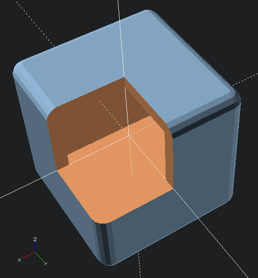
I’m very proud of a particular design method in the CuttleBot.  I designed the organic and non-angular design of the CuttleBot body by using the “hull” function and several carefully deformed and positioned spheres.  However, it would be very difficult to hollow out the interior – since it would mean designing another entire structure to be subtracted out.  Instead of creating the outside shape I wanted and using difference to hollow the interior, I designed the interior shape and used that to create the exterior with the “minkowski” function.

Here’s an OpenSCAD code example:

difference()
    {
    //  Traces sphere around exterior of cube
    minkowski()
        {
        //  Main object
        cube(50, center=true);
        //  Object to trace around main object
        sphere(r=5);
        }
    //  Removing center of object
    cube(50, center=true);
    // Arbitrarily large cutout
    cube(10000, center=false);
    }
Minkowski sample

Minkowski sample

Although, now that I think about it, there’s probably an even cooler way to do this!  Since the above code needs to refer to the “target” object twice, that code can be simplified by using the “children” function.  The below code creates an identical shape.

hollowObject(5) cube(50, center=true);

module hollowObject(thickness)
    {
    difference()
        {
        minkowski()
            {
            children();
            sphere(r=thickness);
            }
        children();
        //  Arbitrarily large cutout
        cube(10000, center=false);
        }
    }

The great thing about a modeling process like this is it allows  you to maintain an even thickness all the way around the model.  This would be increasingly difficult as the complexity of the underlying model increases.

Lastly, to return to the model, after hollowing out the interior of the CuttleBot, I added areas for the pins to connect the sections together.  The body of the robot is in three sections – the head, the mid-body, and the tail sections.

There’s still more to do on the model.  Ideally, I’d create a way to open the robot without having to completely take it apart each time.  A hinged door would work fine.  Also, I should probably add an area where one or more micro servos could be zip-tied or otherwise secured in place.  Also, I’ll need to modify the robot’s head later on to allow for multiple (smaller) tentacles and channels for adding wiring for LED’s to the eyes.

There’s also the whole “adding electronics” thing.  You know, to make this less a puppet and more a robot.

Companion Robots: Building Robot Friends
  1. Cephalopod Robot Friend, the story so far
  2. Cephalopod Robot Friend Progress
  3. CuttleBot Body and OpenSCAD Design Tips
  4. An Assembled CuttleBot Body
  5. Building the Monocle Top Hat Cat for #MicrobitVirtualConcert
  6. Companion Robots and Maker Faire Season!

Cephalopod Robot Friend Progress

Well, it’s here!  Today is the start of #CephalopodWeek on ScienceFriday!  There’s a little progress to report on my, tentatively named, CuttleBot.  I’ll post a picture first, then get to describing the progress so far.

Assembled CuttleBot head, side view

In the prior post I listed some of my sources of inspiration.  Another such source is the work of Sean Charlesworth and his awesome Octopod, Gowanus Monster, and newly published Scuttleship.   ((If you like his work, be sure and check out his Etsy shop!))

This slideshow requires JavaScript.

Since I need special connectors for the articulated/articulating tentacles and I wasn’t able to edit the files in OpenSCAD, I wasn’t able to use Sean’s STL files.  However, I really like the aesthetic of his designs1 and how they really evoke the form of an octopus or cuttlefish.  Here’s a mock up I used to help me visualize what a full-scale Scuttlefish head might look like with the tentacles I designed.

Scuttlefish with placeholders for tentacles

Scuttlefish with placeholders for tentacles

Unfortunately, the Scuttlefish head and body parts are just a tad too large for my small printer’s build volume.  However, even if I were using a larger printer, I would still not want such a large robot as I’m hoping for this to be a shoulder-mounted companion.

Thus, I began work creating an OpenSCAD cephalopod cuttlefish head inspired by Sean’s work.

This slideshow requires JavaScript.

Now that I had a design, I set the printer to work over night.  This design is mostly to see if the various parts for the tentacles would work with this head.  Since I want to put some LED’s in the eyes and possibly the mouth, I’ll need to hollow it out later.

The print took a little over an hour for the head.

This slideshow requires JavaScript.

How about a video of it working?

I’m very happy with the progress so far.  If I can shrink down the tentacle mechanisms, I can add more tentacles for more interesting emoting and animations.  The video just shows the results of me yanking the fishing line running through the CuttleBot’s head.

Here’s a few more sketches of how I am planning on putting it all together.

This slideshow requires JavaScript.

I might add some fabric frills / fins, instead of printed ones.  I was also contemplating letting the top “shell” of the CuttleBot be formed from 3D printed spines with a fabric or thin plastic sheeting covering.  This might help reduce weight or allow for internal lights to shine through the body.

Companion Robots: Building Robot Friends
  1. Cephalopod Robot Friend, the story so far
  2. Cephalopod Robot Friend Progress
  3. CuttleBot Body and OpenSCAD Design Tips
  4. An Assembled CuttleBot Body
  5. Building the Monocle Top Hat Cat for #MicrobitVirtualConcert
  6. Companion Robots and Maker Faire Season!
  1. Cephalopod Steampunk?! []

Cephalopod Robot Friend, the story so far

Quick lead in:  I am trying to build a cephalopod robot shoulder friend.

I was disappointed that I only learned of Glow Ascii‘s owl robot companion, Archimedes, after Maker Faire Bay Area 2018.  Over the year, leading up to Maker Faire Bay Area 2019, I followed Odd_Jayy‘s spider/bowler Anansi robot companion with similar rapt interest.

Still high off Maker Faire 20191 , I was also excited by the prospect of #CephalopodWeek on NPR’s ScienceFriday.  Between cuttlefish, squid, and various octopuses (especially the “Opisthoteuthis Adorabilis“), there are a LOT of awesome little friends to consider making.

While trying to avoid work, I posted a sketches to Twitter.

This slideshow requires JavaScript.

Last week I started designing a few parts, drawing from some experience designing printable prosthetics for the E-nable project a few years ago.  I was trying to build it out of what I had on hand, which did not include elastic cord.  I thought a zip tie might provide enough “spring” and “give” to work.

This slideshow requires JavaScript.

I admit, this was a total mess.  I suppose it is only fitting I use this meme featuring Dr. Zoidberg.

Thanks Dr. Z

Thanks Dr. Z

Thanks to some kind encouragement from Odd_Jayy, I kept moving forward.  Rather than focusing on the end of the tentacle, I got to work on the basics of the mechanics – channels for the elastic cord and fishing line, wedges cut into the faces so the tentacle could articulate.

This slideshow requires JavaScript.

The tabs on these parts were too thin and tended to break when I assembled them.  However, the next version worked really well.

This slideshow requires JavaScript.

These worked a lot better, so I started cranking out parts.

https://www.youtube.com/watch?v=QLUkgY5XDNg

https://www.youtube.com/watch?v=H–MmB1uzrA

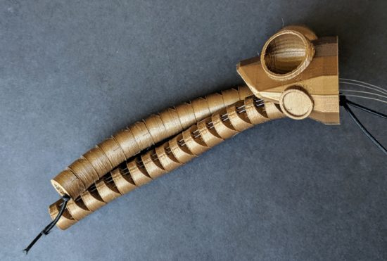
The nice thing about these tentacles is that they look somewhat lifelike without actually requiring much in the way of electronics.  As long as I can design a body/housing and put a servo inside, that one servo could possibly pull on 8 different sets of fishing line to articulate all the tentacles at the same time.  And, since it’s just fishing line, there’s no special routing of brake cables necessary.

The tentacles are somewhat larger than I would like, so that means where they connect to the body needs to be similarly large.  There’s definitely room for improving the tentacle segments.  I’ve already designed two different “ends” for the tentacles, so they’re rounded instead of exposed connectors, fishing line, and elastic cord.  Also, to make the curling tentacle look better, I should angle the the top and bottom of each segment.  Another improvement would be to rotate the articulation angle for different segments to give the tentacle a more organic look when moving.

However, if I don’t get working on the body of the robot, it’s not going to ever get done.  Given the size of the tentacles, I’d need to have them all on one side, lest the little robot take over my entire shoulder.  Here are some “Cuttle-Bot” sketches along with a robot body design.  If you look at the design, you’ll notice the connectors are rotated to different angles.  This is so that the tentacles would each spring back together towards each other – and then splay outwards when articulated.

This slideshow requires JavaScript.

However, this last design takes FOREVER2 to render in OpenSCAD.  This is at least partially due to design and code inefficiencies, but also due to the number of spherical parts, facets, and “hull” operations needed to make these parts work.

I think I may want to try shrinking the tentacles slightly so I can build a smaller-bodied robot.  Either way, I have to get cracking on at least some kind of housing/body and mounting motors/electronics before I can keep moving forward.

Companion Robots: Building Robot Friends

  1. Cephalopod Robot Friend, the story so far
  2. Cephalopod Robot Friend Progress
  3. CuttleBot Body and OpenSCAD Design Tips
  4. An Assembled CuttleBot Body
  5. Building the Monocle Top Hat Cat for #MicrobitVirtualConcert
  6. Companion Robots and Maker Faire Season!
  1. LONG LIVE MAKER FAIRE! []
  2. Well, a little over 5 minutes []

DIYFaire.com: Hello Maker World!

There were dark rumors going into Maker Faire Bay Area 2019 which imparted a cloud over the event.  On June 8, 2019 I was still reeling from the news Make and Maker Faire were closing, so I bought a domain and created a website (DIYFaire.com, now lapsed) with the idea that come January of 2020 perhaps I might find a way to get together again with far flung friends on the same weekend.

The website is gone, but Archive.org remembers and the WordPress installation may yet exist.  Although I write this preamble on 7/12/2023, the day I will remember I’d heard Maker Faire was coming back, I’d like to preserve that post on 6/8/2019 here on my main blog:

Make: and Maker Faire may be gone. I hope they’re not. I hope Dale and the Make crew figure out a way to rise up. People made things, just for the sake of making them long before Make they’ll continue to do so. Knowing people will continue to make doesn’t really salve my sense of loss. I feel like we’ve lost too much, mourned too much, and it still feels so raw.


At the same time I’m not going to miss Makers, because I don’t have to. Makers are not going anywhere. I am going to miss the opportunity to meet up with Makers and far flung friends at least once a year at Maker Faire.


Fortunately, the end of Make and Maker Faire are not the end of the friendships sparked and forged there.


Here’s my promise to you, right now. On the weekend of May 16-17, 2020 I’m going to travel out to San Mateo. I’m going to stay out there for the weekend. And, I’m going to bring some stuff I’ve made or been working on.


I don’t have any idea what “DIYFaire.com” is going to be. If nothing else, it’s a place holder.


It’s a “save the date.”


If I don’t see you sooner, dear friend, let’s start making something together right now. Let’s make a plan to hang out, share things, and continue our friendship. You’ll forgive me for ending with someone else’s words.


“And if you’ve come this far, maybe you’re willing to come a little further. You remember the name of the town, don’t you?”