More progress on a fully parametric prosthetic design
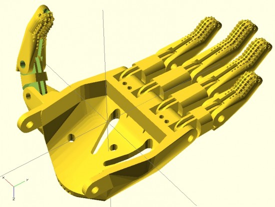
Here you can see the fingers placed appropriately with the palm. I’ve used the same “finger” designs to add a thumb.
For right now, this is just to demonstrate the progress so far. Theoretically, the only thing left to do is crank out an appropriate gauntlet to bring the entire design together. In reality, there’s still a fair amount of work to do. The design for the prosthetic palms was… not elegant. Also, I want to create a separate (but very similar) design for the thumb.1 It is possible that if I improved the finger designs, I might be able to get away without designing a separate thumb.
In the meantime, I think it looks good and would probably be functional as-is.
Onwards and upwards!
Default Series Title
I feel like the thumb should be stubbier, so I’ll go back and adjust the designs accordingly. [↩]
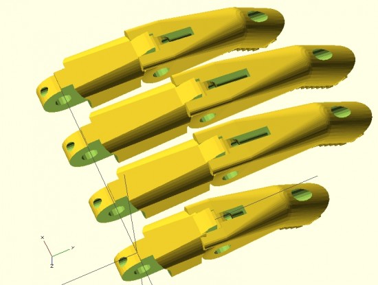
Parametric fingers – different lengths, same scale, with no distortion to hardware
I’m not ashamed to admit it – I’m proud of these parametric designs like few of my other designs. I’ve worked to make this design as customizable and organic as possible. The two modules that define each finger can be customized in two important ways – they can be lengthened1 as well as scaled up or down – without any distortion or change in the size of the holes for the hardware, elastic cords, or tension cords.
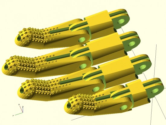
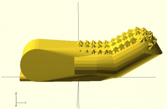
Parametric fingers – with grippy bits
Being able to lengthen2 the finger segments is important because it allows the user to create fingers of different lengths, as normal fingers are of different lengths, all without having to actually scale the fingers to different sizes and without causing a change in each finger’s diameter.
As I’ve discussed in earlier posts, being able to scale the parts up and down without distortion to the hardware holes is important because it allows users to use standard hardware throughout different designs.
For now, it’s back to work on the parametric palm to ensure a proper fit with these parts.
This post is intended as a set of “guidelines” to creating a parametric design in OpenSCAD.
Last Sunday afternoon was spent working out a parametric design for printable prosthetic fingers. Using the OpenSCAD function “hull” it’s relatively easy to crank out a nifty organic appearing design. Admittedly, you have to have a working knowledge the basic union/difference/intersection function first. However, once you do it’s really quite easy.
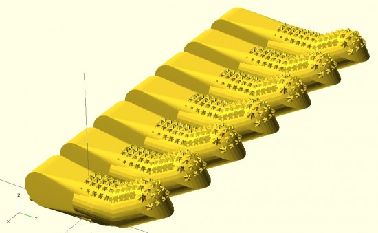
The feature of the design I’m most proud of is the “nail” part of the finger tip. I designed the “nail” by using the OpenSCAD function “intersection()” on two cylinders. The little “nubs”1 consist of a small cube, rotated so a corner is pointed straight up combined, with an identically situated cube rotated slightly.
When I’m designing something to be parametric, I usually don’t really start out designing it that way. I first strive to create a form in OpenSCAD that resembles closely the thing I wish to design. Then, I poke through the design code looking for those elements that are related to the design aspects I’m interested in changing based on parameters. Once located, I replace those parts of the design code with variables that can be specified when the module is called. I realize this is kind of a “high level” description of my design process for parametric things, but it’s still the best description.
Since last Sunday I’ve really done a lot with the design. Some simplifying and a lot of improvements. In the next post I’ll go over these features. I’m really excited to show these off. :)
Above is my first attempt at designing a “solid” finger for the Cyborg Beast DIY printable prosthetic in OpenSCAD.1 The reason this is a “solid” finger is that I haven’t subtracted out any material to allow this partial finger to connect with anything else.
The problem with scaling (up or down) any design that requires fasteners and hardware is that when you do, the holes for the hardware are similarly scaled. This leads to more post-printing work drilling holes to widen them or to find larger fasteners that won’t rattle around in too-large holes.
Thus, if the hardware consists of 3mm screws, the holes for the hardware should be 3mm no matter how much the parts are scaled up or down. To make matters more interesting, not all holes in the model should be excepted from scaling. The above finger tip has a plastic end that is supposed to fit into a mid-finger piece – and those parts should be scaled up or down according to the size of the overall hand. Thus, some voids should be scaled2 and others not at all.3
I’m rather happy with how this finger has turned out so far. It has most of what I understand to be the essential features of the Cyborg Beast fingertips, including little nubs along the finger pad to allow for gripping. I intend to make this an option, in case a user would rather use something like Plasti-Dip to make grippy finger pads, rather than relying on printed plastic bumps.
However, converting a decent design into a parametric design requires a little more work. The way I go about designing a parametric model is to first design one instance of the thing, in this case the finger tip. My next step is to poke through the OpenSCAD code to locate those aspects parts that contribute to the models’ essential features – length of the finger tip, for instance. Once I’ve found these bits, I then try to modify them so that I can insert different variables and arrive at sane variations on the model.
Tuesday afternoon I had the good fortune to talk to Professor Jorge Zuniga of Creighton University regarding his insights on printable prosthetics, measurements of uneffected/effected hands, and various important design considerations. Getting to talk to him really helped crystallize my understanding of the various measurements and the way in which the parts of the printable prosthetic1
Design Ideals
One of the design ideals of the Cyborg Beast prosthetic is to fashion a device that strives for symmetry with the unaffected hand. Thus, all of the necessary measurements are taken from the unaffected extremity. This serves two purposes. First, it allows for the prosthetic to be similar in scale to the unaffected hand. Secondly, the unaffected extremity tends to be, in most cases2 , slightly larger than the affected extremity. The size difference may be due to the unaffected extremity being used more, and thus having more muscle mass, or due to the loss of muscle tone and muscle atrophy in the affected extremity. Either way, a prosthetic designed using the measurements from the unaffected extremity should generally fit the affected extremity. Since this particular prosthetic design uses velcro straps to fasten to the affected forearm, a prosthetic that is slightly too large can easily be adjusted to fit well by tightening the straps.
Another design ideal is to create a core prosthetic design which works for the vast majority of persons.
Critical Printable Components
A rough sketch of the various parts of the Cyborg Beast prosthetic appear above as “Figure 2.”
Palm. This is the part that fits over the hand.
Gauntlet. This is the part that fits over the forearm, between the wrist and elbow.
Four fingers, each comprised of two pieces. The above simplified sketch only shows the fingers as a single piece. Do not let my sophisticated drawings fool you.
One thumb, comprised of two pieces. Like the fingers, the thumb is comprised of two plastic pieces.
Critical Measurements
These measurements refer to the lines labeled in “Figure 1.” All measurements relate to the unaffected extremity.
F5. This is the length of the forearm, from the interior of the elbow to the wrist. While this could be measured along the side of the forearm, it very likely doesn’t matter.
F2 (measured at 1/2 F5). At a location along the forearm, half way long F5, the width of the forearm.
H1. This is the distance across the knuckles, from the pinky to the forefinger.
When I lay my own hand flat on a table top, I perceive that an imaginary line drawn through my pinky and forefinger knuckles would end up being not exactly perpendicular to an imaginary line drawn from my elbow to my wrist. More on this below.
All of that is another way to say that I suspect H1 is not perpendicular to F5.
W. This is the width of the wrist. Rather than being strictly measured from either side of the wrist, this measurement appears to best made using the endpoints of the H2 and H3 lines closest to the wrist.
H2 and H3. H2 is the length from the wrist to the pinky knuckle and H3 is the length from the wrist to the forefinger knuckle.
All other measurements indicated might possibly be useful for refining the design, but they are primarily important for the Creighton University research study purposes.
How Each Critical Measurement Informs Design
F5. Gauntlet length is not longer than 1/2 F5 and not shorter than 1/4 F5.
F2. Gauntlet forearm width is F2.
W. Gauntlet wrist width is W. Theoretically, if the prosthetic’s palm is scaled up to accommodate the wrist width (W), the affected hand should fit under and inside the prosthetic palm.
H3can be used to inform the relative lengths of the fingers to match the overall length of the unaffected hand. This isn’t strictly required for a functional prosthetic. As designed, the Cyborg Beast appears to use fingers of equal length. However, the fingers could be scaled up or down along with the rest of the prosthetic hand. Alternatively, and as will be discussed below, its possible that the fingers could be designed to be of different lengths. Prosthetics for young children should contemplate fingers based upon slightly larger, 1-2cm, measurements. The reason being that they quickly outgrow existing parts.
Functional Design Considerations
Thickness of parts is 3mm – 5mm, 20% fill.
The wrist hinges should line up as exactly as possible with where the user’s wrist bends. Additionally, the wrist hinge should be perpendicular to the line of the forearm/gauntlet.
There should be about 1 – 2 mm of space between the hinge part on the palm and the hinge part on the gauntlet. This allows a washer to be inserted for more fluid movement.
Eliminate square corners when possible, as sharp edges can contribute to possbile injury.
Cosmetic Design Considerations
Using the unaffected hand for measurements also allows us to seek symmetry between the hands.
Advanced Considerations
Degree tilt to H1. As mentioned above, it seems like the “H1” line is not perfectly perpendicular to an imaginary line drawn from my elbow to my wrist. An educated guesstimate would be that there is a 9 degree tilt to this line. While existing Cyborg Beast designs do not include this knuckle “tilt,” including this feature in future designs may allow the prosthetic to appear and function more naturally. However, I don’t know if there’s any real ergonomic benefit to using incorporating this knuckle tilt.
Different knuckle positions for fingers. The Cyborg Beast has a knuckle “block” that positions the attachment points for all fingers in a straight line. The reason for this is simple – it’s a lot easier to put one long screw through the entire knuckle block to secure and strengthen all four fingers at once. At a recent e-NABLE meeting I had the chance to inspect a 3D printed prosthetic which used different knuckle positions for each finger. Rather than all of the knuckles in a straight line, this model featured each knuckle at a different, and more natural seeming, position. While this can appear more natural, I’m not sure there’s an ergonomic or aesthetic benefit.
Different finger lengths. Fingers are different lengths. The Cyborg Beast, with all fingers having the same relative knuckle positions and same finger sizes, has a more mechanical look than might otherwise be possible. I don’t know if there’s an ergonomic benefit to using different finger lengths, but this is certainly something to explore.
Based on the above, I think I’m ready to dive back into the OpenSCAD code and work out a parametric gauntlet, fingers, and thumb. Stay tuned!