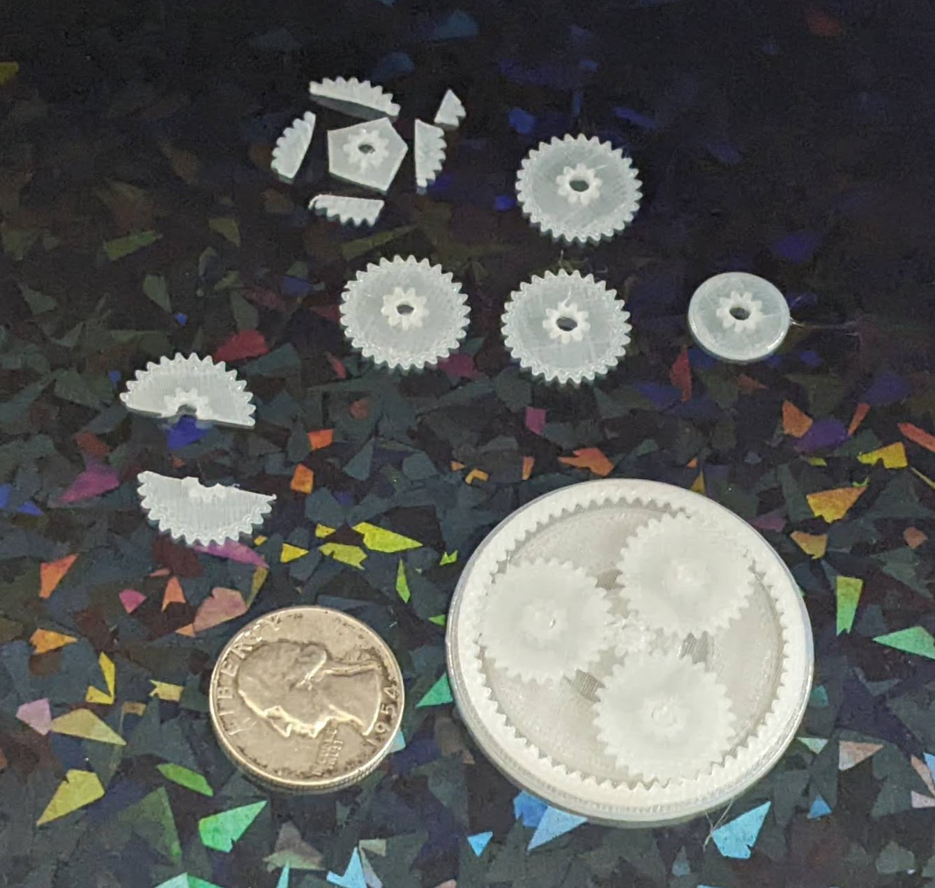
I designed a planetary gear assembly, more to see whether parts this small would even turn out than to actually make a working component. The gears are about 3 mm thick, but half of that is the larger part. I forgot that you can’t have a two-level gear mesh against another identical gear, so these didn’t move at all.
A test planetary gear assembly
I reprinted the parts, this time increasing the center hole size and also removing the teeth off the larger side. It kinda works, but it’s very finnicky. This might be a side effect of these gears being very thin and the teeth very small. I think it’s probably worth sacrificing gear ratio in favor of larger, more consistent teeth.
Small improvements
The OpenSCAD code is a mess, lots of vestigial code remains, lots of non-working parts are commented out, and it all just needs more comments in general. I hate looking at it. But, as one of my favorite memes goes…
I was flipping through my smaller notebook and remembered I’d already posted about a credit card sized design for a protractor and ruler. I decided to connect this to my recent other design and turn it into a short series. This design predates the one I most recently made and shared on this site, thus the title.
While I posted a writeup to Instagram, for some reason I didn’t put anything here?! Other websites go away over time and even if mine doesn’t last forever, well, at least it’s still mine. Thus, here’s the photos:
This slideshow requires JavaScript.
And, just in case1 Instagram completely evaporates, here’s the writeup I posted:
A DIY protractor / ruler / template card.
I needed a quick and convenient way to make straight (ish) lines and angles that I could keep in my small notebook.
The little card is about the size of a playing card and acts like a 5mm increment ruler, 10 degree protractor, and can make it easy to draw a grid.
This all started because I was working on an electronics project, needed some resistors and haven’t memorized the color chart, decided to draw a color chart in my notebook, needed a grid / ruler, decided to design my own after seeing a neat metal one on Kickstarter.
My solution is basically to make a solid for the thin brim + tall cutting edge and then subtract the original SVG shape. I tried it with each of @raster’s SVG’s for the teddy bear, cloud, hexagon, and pacman and they seem to work. Anyhow, here’s the code I wrote instead of doing the work my employer pays me to do:
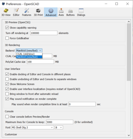
After mentioning long render times on my machine, @raster suggested switching to the manifold 3D rendering backend. Depending on your OpenSCAD version, you might need to poke around to find how to enable this option. It’s absolutely worth your time and should really be enabled by default.
Emmett’s manifold library dropped the render time for one of my designs from 300 seconds to… under 8 seconds. I literally used to avoid hitting F5 on more complex designs or avoid cranking up the facets so I didn’t have to wait for long renders. A single comment from a friend, telling me about an option written by another friend, has completely and permanently changed how quickly I’m able to iterate and design objects forever.
Here’s how you can instantly save tons of time with your OpenSCAD designs:
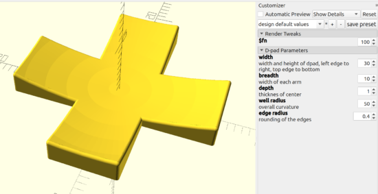
Thanks to @raster, I’m going to do a side-by-side taste test of several different flavors of OpenSCAD.1 To give each one a similar test, I’m trying out my D-Pad design from … uh, earlier this morning.2
Obviously, the good folks working on OpenSCAD have dramatically improved preview/render times over the last four years. The speed boost in using a later snapshot is pretty significant if you’re doing any kind of complex designs. They must be using some kind of cache system to make the render times so fast.
The speed differential between 2024.01.13 and the latest snapshot is so slight, I’m not going to switch things up unless I bump into a design that struggles with rendering some complex feature.
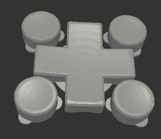
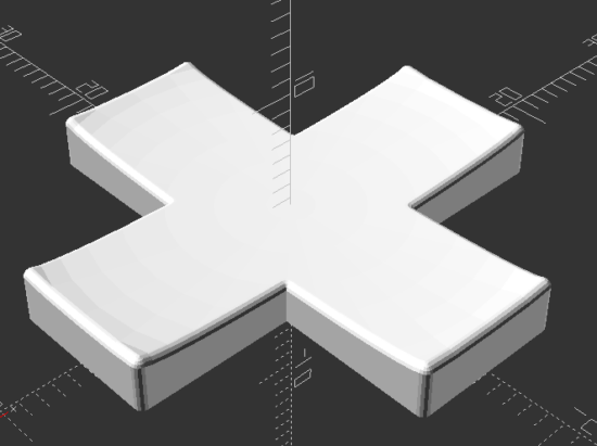
This week’s topic related to @deshipu’s directional keypad designs. The directional pad is clearly the most complicated part of the design. The four buttons are basically just cylinders that can be created in several different ways.
After staring at the design a little longer, I changed from my original design idea to creating a 2D cross, extruding that, subtracting out the curved area described by a sphere (a homebrew hack I’ll describe below), using the minkowski function to surround the entire surface with a small sphere to give it a rounded look, then cutting the bottom off to ensure it is flat. I didn’t include a flat cylinder as in the original design above, but that’s a trivial addition. The downside? This is a 5 minute render on my machine, largely due to the minkowski function.
You’ll notice I use “offset” to reduce the size of the directional pad, because I knew I was going to round it all with the minkowski function in a few lines.
The directional pad is actually just a rectangle, run through a for loop once to rotated it by 90 degrees, before being extruded to the specified height.
The last two lines of code are used to create a large cylinder, larger than what I knew the pad would be, then mirrored in the Z axis to cut everything below the XY plane.
As in prior designs, I pre-define “fn” to be a “pow(2,5)” so that I can use a low exponent to iterate designs quickly, then crank it up for a detailed design.
The hack I use the most often here, and the one I’m the most proud of, is where I make a sphere like “sphere(r=0.5)” and then scale it by whatever I need. Since the sphere has a diameter of “0.5” mm, the actual sphere is 1mm in diameter – so when I scale it in the XY by 30 and in the Z by 2 (since the edges of the keypad are 3mm tall and the center is 1mm tall), the diameter is now 30mm and the height is 2mm. This little trick, of being able to scale a sphere to the exact size I need has come in handy countless times.
I’m not the best programmer, not the best at OpenSCAD, but I’m kinda happy that I was able to build this in about 31 lines of code. :)
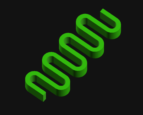
“I’m trying to come up with a good way of creating this in OpenSCAD… I have something using a bunch of hull’d cylinders but I’m wondering if there is a better/easier way to do it.” @rasterweb
A friend posted a design pondering whether there was a better way to design an object in OpenSCAD. As so often happens when I approach a 3D design, one solution pops up in my head… and is immediately discarded as garbage. That first thought was to create a negative of the interior of the spring, then iterate along the length of a stretched cube.
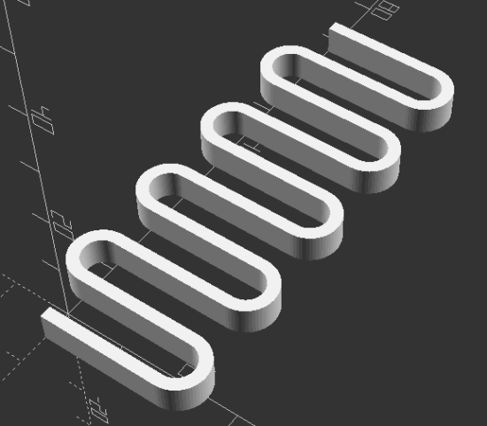
In the end, I opted for1 creating a flat version of a single “loop”, made from differenced hulled circles, repeated over the number of desired loops, then trimming alternating ends (so it wouldn’t look like a chain).
I like to use OD/ID/OR/IR to mean outer diameter, inner diameter, outer radius, inner radius.
I think the “spring_loop” module could be simplified slightly by calling another module which creates each hulled circle, but weighing the additional module code against just retyping a little code I opted for what got it done faster.
I like to specify the facets on circular objects right at the top of the file. This way, I can adjust the smoothness of the object by just changing just the exponent part of the $fn system variable.
Reasonably parametric. There’s some additional further optimization that could be done in the spring alternate end clipping.
Can’t wait to see what @rasterweb makes with a 3D printed spring!
My experiment with a multi-piece turn around didn’t work. The idea was for a multi-segment turn around where each string could be tightened and that portion of the turn around would be able to rotate as needed independent of the other pieces. I simply did not account for the kinds of stresses the pieces would be under through normal use and string tension. Each segment deformed, resulting in none of them being able to rotate and the slightly less rigid turn around bowing slightly under the pressure. I couldn’t get a great picture of the deformed parts, but perhaps this will give some idea.
This slideshow requires JavaScript.
In the end, the best result for my ukulele has been a 3D printed turn around, finely sanded smooth, unadorned by paint, with a small amount of lubricant (I’ve used machine oil) over the metal bridge and across the turn around. These simple elements have, hands down, beat the over engineered / over designed pieces above. If they were printed out of a more rigid material, milled or turned from solid metal, created by using a system of washers, or made using a full length bolt, I’m sure it would have worked better.
The design of my turn around uses captive nuts in the plastic core, secured by bolts on either side. This ends up being dramatically easier and cheaper than trying to source very long Chicago bolts and posts – but has a minor downside in that the two bolts don’t actually connect. As long as the material between the two bolt ends is strong enough to withstand the continued forces of four strings under tension, there shouldn’t be a problem. However, even printing the turn around with the best orientation for printing strength in PLA didn’t result in a part that could withstand these forces for a long time. 1 One of my ideas for this part involved using bolts that were possible slightly longer or of different lengths so they would both tighten slightly into the same captive nut, resulting in one “continuous” piece of metal for the turn around core, then using washers to ensure / assist in minor distance adjustments.
Here’s how it looks today:
This slideshow requires JavaScript.
I don’t plan on any more improvements for this particular ukulele. I’ve deeply enjoyed playing it since it became “finished enough” to be playable in August of 2022. That said, I’ve been thinking about how I would create another one.
CNC Cut Wood. I spent the vast majority of the time on this project just rough cutting the wood to size using a combination of hacksaw and coping saw blades. I spent a ton more time shaving wood off the neck using rough files. Starting with a piece of wood that was already the approximate dimensions and only needed finishing would feel like starting at the 90% mark.
Different Wood. I went with mahogany for a variety of reasons – but cost was one of the biggest and dumbest of these. The difference between a plank of mahogany for $10 and the most expensive wood from Rockler at maybe $30 is a rounding error when the project took more than 100 hours of my time. I’ve suggest that wenge, zebrawood, ironwood, or walnut would be my choice for another attempt. Of these, I am leaning towards walnut for a deep brown, possibly gray finish.
Strap Attachments. The strap was not quite an afterthought. I had always planned on using nylon webbing / seat belt material for the strap and had designed printed strap buttons for hooking the strap onto the ukulele, but in the end I just couldn’t bring myself to drill holes in the finished uke. This was just as well since I had wanted to try using some paracord in a project for a while. After using a flame to seal the ends of the paracord and webbing, the result was way too thick to use in my sewing machine and had to be hand stitched. I’m not great at hand sewing, but it is functional. Given the dark colors of the thread, paracord, and webbing, the haphazard stitching isn’t very noticeable. If I really took my time with it I might be able to do a better job. If it came to that I might want to use some silver or light gray thread to add a little pop.
Acoustic Improvements. I’ve noticed a dramatic change in the quality of the ukulele sound when I place a book, empty box, or large piece of rigid cardboard between the uke and myself while I’m playing it. I’ve thought about how this could be incorporated into a new design by creating a system for bolting, attaching, or otherwise connecting a larger section to the ukulele. Another incredibly interesting option is the plastic sheet used by TitchTheClown. He used thumbtacks to secure a sheet of plastic from a soda bottle against the ukulele, then a heat gun to tighten it into something like a drum surface.
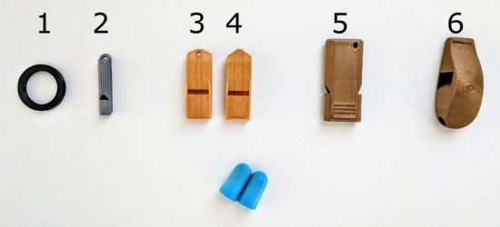
Whistles have been a staple on Thingiverse for years, probably because they’re such a small, simple, and impactful way to demonstrate the usefulness of a 3D printer. 1 I don’t know how many there are, but there are a LOT of whistles on Thingiverse. I’ve been curious about which whistles on Thingiverse are the loudest and conducted a semi-scientific experiment to figure this out.
Six whistles
I say “semi-scientific” because I don’t have a decibel meter.2 My methodology was to have my family at one end of the house while I went to the other side, closed the door, put in my earplugs, and wailed away on six whistles as hard as I could. In any case, here’s my findings:
Name
Thingiverse ID
Mass (grams)
Price
Print Time (minutes)
Rank
Decibels
Extremely loud and compact emergency whistle [v1]
2933021
3.9
$0.12
22
1
TBD
2 chamber whistle (LOUD) [w5]
2616512
8.1
$0.24
49
2
TBD
Extremely loud and compact emergency whistle [v2]
2933021
3.7
$0.11
18
3
TBD
v29 (Over 118 db!)
1179160
13.9
$0.42
90
4
TBD
Emergency Whistle with Solidworks 2014 source
495172
1.2
$0.04
7
5
TBD
Whistle Ring Modified [v2]
2027115
1.6
$0.05
9
6
TBD
I added a few columns that may (or may not) be of interest to you. I indicated the weight of each whistle, because sometimes I want to know how many whistles I could produce off a single spool of plastic.3 Sometimes I want to produce the loudest whistle for the time I have to produce a whistle.4 I showed the cost per model5 , because it brings me so much joy to know I can make my daughter’s classroom louder than a jet engine for less than the cost of a pack of gum.
I know there are a number of important variables are are simply not addressed in this test. Different frequencies sound louder or might be easier to hear through the door. I tried to blow each whistle the same amount, but some whistles are louder with less forceful or more forceful blows. Once that decibel meter shows up, I’ll be sure to post another update.
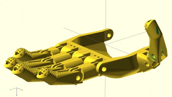
My overall designs for a printable parametric hand are still far from done. And, yet, I’ve come a long long way since jumping headfirst into the realm of open source prosthetics a little more than 30 days ago.12
Forgive the digression, dear reader, before I return you to considerations of prosthetics. After visiting the Asian Art Museum today with the family, I am feeling particularly inspired to discuss dualities.3 I find I am an often-inspired person. This is a very charitable way to describe myself by what would otherwise colloquially and clinically be considered ADHD. When I am inspired by a new topic, I tend to jump right into it – reading voraciously and trying to learn as much about it as I can. When this happens, I also tend to set aside whatever thing I was most recently working on. This means that recently I’ve done little work on drawing robots (big and small) and a multitude of other small projects that would otherwise be just amazing. However, such inspirations/distractions are not only external to a project – but can also be very much internal to a project. Consider, for instance, feature creep – the adding of ever more features to a project, usually at a faster rate than which features are resolved and refined. In order to combat this aspect of my nature, the wanting to add more and better features, I have developed a coping mechanism. To prevent myself from falling down the rabbit hole of features and improvements, I jot them down someplace – either in a blog post4 , in an email to myself, or in a notebook.5 I find that once I’ve externalized and memorialized an idea, I can continue working on a project unfettered and undistracted these other ideas.
To this end, and in the spirit of open source ideals, I will jot down some ideas while I have them:
How large and how small are prosthetic designs typically scaled?
I wanted to have a range of sizes for which my designs were optimized. My guess would be no smaller than 85% and not much more than 160% of the size of the existing Cyborg Beast. Jorge Zuniga was, again, patient enough to discuss this with me. His estimate of a range would be between about 105 – 150%.
What is the diameter of the Chicago Screws typically used in the creation of a Cyborg Beast?
From the retailer’s website, it appears the “barrel” diameter is 0.2 inches, or 5.08mm. I’ll need to make some adjustments to holes for the Chicago Screws in the designs.
How important is hyperextension of these fingers?
The designs of the Cyborg Beast include fingers that can bend “backwards” very slightly. Each finger joint includes a “stop” at the back of the joint. While certainly useful, I question their necessity. I previously designed a connection system for printable snap-fit parts ((For use in an equally noble project)) that connect very tightly and/or bend with a user specified degree of movement. The point with me mentioning these parts is that the “stop” used at the back of each knuckle and joint in the Cyborg Beast may not be necessary at all.
How necessary are metal Chicago Screws to strength and durability of the hand and fingers?
Before you laugh, consider this question – what is the weakest point of any given finger which uses a metal Chicago Screw when having to deal with lateral forces? I would postulate the weakest points would be those thin plastic parts surrounding the Chicago Screws themselves. Thus, even though the hand incorporates metal pins, I have to wonder just how much strength they are providing to the overall device. It would be easy to conceive of a plastic prosthetic hand that was so small that there wasn’t a lot of plastic around each metal screw6. In such a case, the weakest points would be plastic surrounding the metal parts. Extending this conjecture, of what use are metal fasteners to a design that is primarily plastic? The best guess I can offer is that they allow reliable and smooth operation.
Work on proportional fingers
In designing the fingers, I worked to be able to make them customizable in several different ways. The user may specify whether the fingers have the “star grip” pads, whether the finger should be slightly shorter or longer, and scale the finger up or down – without distortion to the hardware and cord channels.
I need to add at least three additional options to these parametric designs. The designs should include the option to add “mouse ears” and easily removable support structures. Additionally, the design should also allow the user to change the diameter of the finger. I did implement this, somewhat, in part of the design. Without implementation throughout the entire design, these partial attempts aren’t helpful.
In creating the fingers shown above, I adjusted their lengths to conform to the measurements of my own hand.7 Next time, I think I would also measure finger diameters.
I think I should create a way to prevent finger parts from being mixed up accidentally while printing. A possible solution is to include “mouse ears” with each finger – but embed an identifying mark in each mouse ear to label the parts.
Ideas on making a better parametric palm
The palm should be redesigned so that the fingers, at the appropriate lengths, would fit into it. I designed the fingers quite a while since working on the palm. I haven’t had a chance to ensure the parts would mesh well without adjustment to the scale.
On an entirely different note, I have an idea to redesign the entire palm. By carefully placing deformed spheres, I was able to design a palm. Using a similar process, I subtracted out a void for the user’s hand. The result is a palm with an uneven thickness throughout. Uniform thickness isn’t necessarily an interesting or useful goal. That said, it could lead to a reduction in unnecessary plastic. If I were to redesign the palm, I could design the internal area first8 – and then use the “Minkowski” function to create a uniformly thick shell around the internal form. The bottom would have to be sliced off and the original internal area would need to be subtracted from it.
Ideas on making a more realistic hand
My designs so far are based primarily on the Cyborg Beast, with some minor changes. The “Flexy-Hand” appears to be very organic and realistic. It also features flexible printed connections between each finger segment. Additionally, each finger is comprised of three segments – rather than two like the Cyborg Beast. Interestingly, since the flexible connections between segments allows the hand to return to an “open” position, the hand only requires five tension cords – rather than five tension cords and five elastic cords. The fingers appear to not have any “stops” behind each joint. I have to wonder how having three segments to each finger impacts the function. Does it allow the hand to better grip things? Does it make the hand less sturdy?
Masculine/Feminine hands
One well-intentioned comment to my latest designs is that they are “pretty.”9 While I accept the compliment with the spirit in which it was given, it immediately made me wonder – is the hand I designed “feminine?” Then it occurred to me that with more design effort, I could make “feminine” and “masculine” version of these hands. I think the primary differences would be two-fold – thinner fingers and a less “hefty” palm for a more feminine version and a thicker and perhaps more “blocky” palm for a more masculine hand.
New developments
There have been a number of interesting and new developments and experiments of late.10 In no particular order, these ideas are:
A few days ago my daughter and I were jotting down some ideas in my sketchbook. As we did so, she saw some of the notes from the e-NABLE meeting on 3/21/2014 – including several sketches. We discussed the problem – affordable, customized, and comfortable prosthetics. We talked about amniotic band syndrome, how fibrous amniotic bands affect fetuses, and the different ways in which these bands can cause11 deformities to single fingers, whole hands, and a range of changes in between. I explained how Mr. Jose Delgado Jr. had a $42,000.00 myoelectric prosthetic, the problems he has with that prosthetic, how and why he prefers his $50.00 printed replacement, and how for the price of his one prosthetic people could make 840 more prosthetics.12 She asked, “Why can’t someone use a stump to operate a hand?” I replied that this was exactly how these prosthetics worked – and I drew a few simplified sketches of the Cyborg Beast. Her next question was, “Why can’t it move side to side?” I said that Mr. David Ogreman had designed such a prosthetic.
Default Series Title
My first concrete step was going to an e-NABLE meeting in San Francisco on 3/21/2014. [↩]
The above picture is slightly misleading. I haven’t confirmed that the fingers I’ve designed will properly fit into the palm that I’ve designed – or that the thumb would work at all. Thus, the picture is partially a parlor trick and partially an indication of where I hope to take this design. [↩]
Many of the gods and goddesses in Eastern religions embody dual natures – creation/destruction, life/death, etc [↩]
In one of my several different blogs. Besides, what could be more ADHD than having 3+ blogs?!? [↩]
You may not find this as amusing as I do – but I probably have about four different sketch/notebooks. [↩]
I don’t even know why I’m saying “of late” when I’ve really only been involved a little over 30 days. I guess becuase these developments are new to me? [↩]
Please forgive my lack of a more politically correct term. If you’ve got a better or more sensitive phrase, please let me know as I will gladly adopt it [↩]