Welcome to Radio Shack! Don’t let the door hit you on the way out!

Welcome to Radio Shack!

Welcome to Radio Shack!

This post could also be entitled, “Customer Service Fail Day.”

TLDR:  If you’re looking to build something, don’t even bother going to Radio Shack or Fry’s Electronics.1 Even in the SF Bay Area they won’t carry what you need and if you leave feeling disgusted with their customer service, you’ve gotten off lightly.  Buy your parts online from someplace awesome like Adafruit or Sparkfun or someplace else that truly cares about what they do.

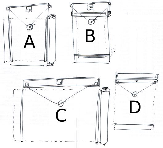
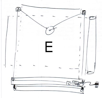
TLRA:2 Today I went looking for the last few parts I need to properly finish up my drawing robot.  If I was able to locate these parts, my ‘bot would be totally ready to place on a wall and start drawing.  Even at the risk of overpaying for a minor part or two or spending way too much time trying to locate a mostly inconsequential part, I wanted to try to finish everything this weekend.

I really should not have bothered.  I should have just stayed home in my jammies, surfed the net for the parts I needed, and then waited a few days for them to arrive.  If I sound disappointed, it’s probably just because I am.  I went looking for some fairly basic parts:

  • Eight (8) M3x8 bolts
  • Multicolored ribbon cable with at least 4 conductors3
  • Male and female connectors4

I would have been perfectly happy to substitute nearly any of these items for something even remotely similar. I would have settled for single color ribbon cable, bolts anywhere from M3x6 – M3x10, and really any kind of male and female connectors that would work.  However, all of this is besides the point.

The first stop was a national chain hardware store.5 I honestly wasn’t sure I wanted to visit this store again,6 but I had a $5 coupon and I was pretty sure I would find the metric bolts I needed.   On a recent trip to the local hardware store I rooted around their nut/bolt area only to discover that someone or someones had mixed many of the M3 and M4 bolts.  It was such a mess that I didn’t want to try them again.  I paid a lot more for the eight bolts than I was expecting to, but at least I found the exact number of the exact bolts I needed with no additional hassle.  While I was there I also picked up an inexpensive 15′ white extension cord so that my ‘bot could have an extension cord of it’s very own.

The next stop was the local Radio Shack.  I haven’t been to a Radio Shack in a really long time – mostly because I’ve had such unsatisfactory experiences there.  However, given Radio Shack’s long history of being THE place for Makers to find parts and supplies and their apparent return to their Maker-roots, I was willing to give them another shot.  The local Radio Shack is in the middle of a run down strip mall nestled between a Chinese take-out place and something else I don’t recall.  I honestly thought the Radio Shack was closed until I got right up to it.  As I walked up I held the door open for an older Asian lady.  She walked in ahead of me and told the clerk, who was on his cell phone, that she needed to borrow $10.  Assuming that these two people knew each other, I just went ahead and looked for where they keep components.  Electronic toys up front, phones on the left, tablets and computers on the right, and towards the back under the television blaring some sports game7 I figured I might find some electronics components.  The “aisle” was probably only about six feet long and about four feet high.  Towards the entrance there were a few Arduinos and books8 on the left, speaker wire on the right, and at the back of the aisle9 on the left was a set of pull out drawers with various bits and bobs that could be used in electronics projects.  Except none of it was what I needed.  The other employee, a woman, walked over and asked if she could help me.  I explained that I needed some ribbon cable and connectors, then I had to explain what they were.  Once I had done so she pointed to some colored single-conductor wire.  I tried to explain that a ribbon cable had more than one wire in it – and this time she pointed to the same single-conductor wire and then another set of single-color wire of a different color.  Seeing that this was completely futile, I asked about connectors.  Quite helpfully, she pulled open the drawer marked, “Connectors” and told me that any of them would work.  I explained that I needed something I could solder to the wire I was hoping to buy and then be snapped together or pulled apart as needed.  She picked up a random baggie of plastic and metal and told me that all the parts were in there.  I told her I needed male and female parts.  “Yeah, it’s in there.”  Since she was pointing to a wire crimp with an eye terminal, I knew that either she had no clue what she was talking about or that she just didn’t give a damn about what she was saying.  I honestly cannot understand how that store can justify having two employees at that location at any time, let alone at 2pm on a Sunday afternoon when I was literally the only potential customer around.  There cannot possibly be enough consumers of radio controlled cars to keep the lights on in that store.  The selection of parts was just abysmal and the service could only have been worse if the staff cared enough to actively insult me.  After rooting around in the component drawers for a little, I gave up and walked out.  Two employees and neither of them said a single thing as the only potential customer they might see that day walked out the door.

My third stop was to Fry’s Electronics.  The parking lot was packed and the store was busy.  What I love about this place is the parking lot is ALWAYS packed and the store is ALWAYS busy.  It doesn’t matter if I come by first thing in the morning, or in the middle of a weekday, or a Sunday afternoon – it’s nearly impossible to find a parking spot and there are tons of people in there.10 While their staff aren’t always super helpful, I’ve found that about every other employee is actually somewhat knowledgeable about their wares.  I walked into the store, past the bargain bin items, took a left at toys, and walked on towards PC components.  Since ribbon cables and connectors are the sorts of things one would find inside a PC, I figured this would be the place to start.  At the podium stood three young men dressed in black pants and white shirts wearing name tags – I assumed they worked there.  The three of them were talking to one another and continued to do so as I stood in front of them.  Finally, I said, “Hi!”.  The three of them looked at each other and one of them, after several seconds what seemed like a nonverbal game of chicken to see who could go the longest without acknowledging the customer, one of them finally asked how he could help.  I explained I needed ribbon cables and connectors.  He showed me to wire and speaker wire.11 I explained that ribbon cable involves having multiple strands of conductors attached together to form a sort of “ribbon” of wires that ran together.  He must have been spying on me at Radio Shack since he ran through the process of pointing to colored wire, then showing me two different colors of wire.  After holding up a thick piece of electrical cord involving two-conductor wires each separately shielded, but attached by plastic, and miming what it would look like with many more wires along side it – but not as thick, he seemed to understand what I was talking about and took me towards some computer ribbon cables and connectors.  After an afternoon of searching I felt that I had finally arrived at the right spot.  I asked about male and female connectors or perhaps some male and female headers or anything of the sort he looked back over his shoulder towards his comrades and gestured vaguely towards the wall of parts in front of me and suggested I could find what I needed there.  I asked him a few more questions while I rooted around for something that could work.  Finally he asked if there was anything else I needed.  I could tell there was no way this guy was going to help me any further so I thanked him and let him go.  I ended up buying some male headers and a set of 4 pin connectors.

Here’s what I’ve learned from my experiences today:

  • Radio Shack is a big fat waste of time.  I wouldn’t even buy a remote controlled toy car there.
  • Fry’s Electronics is a big fat waste of time – unless I am in need of an off-the-shelf computer component and require zero assistance.
  • Buying parts online for a better price is absolutely, positively, worth the wait.
  1. Photo courtesy of Giampaolo Macorig []
  2. Too long, read anyhow []
  3. For extending the motor leads []
  4. So I can swap the motor leads easily []
  5. The name of the store rhymes with “Orchard Supply Hardware” []
  6. About two months ago I went there looking for a replacement faucet spray head for our sink.  They were out of stock and said it would be in stock in two days.  I returned in two days and they didn’t get it in.  I was told they would have it in the following day.  So, like a moron, I came back.  They still did not have it.  I went to the local Ace Hardware and they had five of them just sitting on their shelf.  DONE. []
  7. You know, the one with the ball []
  8. A seemingly grudging token nod towards Makers []
  9. ALL the way at the end, a whole five feet away []
  10. Hey, Radio Shack, it’s 2pm, do you know where your customers are? []
  11. Deep breath now []

Overengineered Bolt Endcaps, Case Holder

Simplicity itself

Simplicity itself

I’m still working on building out an awesome drawing robot.1  I’m designing printable parts to be installed into a left over wooden box for holding a paper roll, filament spools, stepper motor mounts, and a few more bits.

  • PolagraphSD case – discussed here – done!
  • Mounts for a paper roll – discussed here – waiting to upload…
  • Filament spools – discussed here – waiting to upload…
  • Stepper motor mounts – discussed here – waiting to upload…
  • Filament guides – discussed here, revisions described below – waiting to upload…
  • Bolt end caps – discussed in this post – waiting to upload…
  • PolargraphSD case holder – discussed in this post – waiting to upload…
  • Pen holder/gondola – TBD2

You may3 be wondering why I’m waiting to upload all of these parts.  The simple reason is that as I design and install each part of the overall robot, I find that a given part might need to be redesigned or might be better design in another fashion.  I’d hate to have someone print up some lousy parts and be stranded with a bunch of junk.

  • The ‘Bot So Far
    • Right now the robot sits a few feet away from me almost totally assembled.  I’m really excited about it.  I’ve mounted the PolargraphSD brain to the right side of the project box so that it would be easy to run the power cord to it.  While I do like the Platonic ideal of the perfectly symmetrical robot, my more practical Aristotelian side won out.  The upshot is that the leads I originally soldered to one of the motors is totally unnecessary and the leads I originally soldered to the other motor are woefully inadequate.
    • There’s not a lot left to do.  Once the motor leads are extended and the robot mounted to a wall, it will be totally ready to go.  I’ve realized that the slides I’m using to mount the paper roll are long enough for me to attach a set of wall mounting brackets.
  • Revisions to Existing Parts
    • Filament Guides.  I designed these 2mm too short.  While this almost certainly wouldn’t be a problem, these pieces are so easy to print that it just doesn’t make sense to live without the benefit of a part that works better.  If they’re too short it is possible for the monofilament line to rub against the wood of the project box – which defeats the purpose of having the filament guides in the first place.
  • Recommended Changes to Existing Parts
    • PolargraphSD case.  It turns out that just above the two Stepsticks in the PolargraphSD there are a pair of three headers with a jumper on each.  The lid for the PolargraphSD case I designed didn’t adequately take into account their dimensions, which kept the lid from closing cleanly.  I used a pair of wirecutters and then needlenose pliers to just rip the unnecessary bits of plastic out.  You would barely notice the change unless you knew4 where to look.  I’m not going to bother to reprint this part because that’s a lot of time and plastic to use for a feature that really doesn’t matter and is barely noticeable.  I’ve updated the OpenSCAD code for this part, so anyone who prints from the latest revision would automatically benefit from this change.5
    • Spools.  For instance, ideally I would have printed the two spools with a slightly smaller radius on the edges of the spool.  As they are now they tend to bump a little against the bolts holding the motors into the motor mount.  Making it just 1mm shorter would do wonders.  There are a few easy fixes for this. The one I’m using for the moment is to just raise the spool on the motor shaft so that it doesn’t bump into any of the bolts.  I should point out that this wouldn’t be a problem at all if only I had plenty of short M3x8 bolts.  Right now I’m using M3x16 bolts with three nuts on them to hold the motor to the motor mount.  This means the bolt head and the nuts get slightly in the way of one of the ends of the spool.  Just using shorter bolts would instantly fix this problem.  I’ve also sanded the end of the spools that fits onto the motor shaft.  If I put more elbow grease into it, this would also fix the problem – but why bother when I can just raise the spool on the motor shaft for now and pick up some short M3 bolts later?6
  • Bolt End Caps
    • Today I installed the motor mount slides in the project box, the spools on the motors, the motors into the motor mounts, the motor mounts onto the slides, and the filament guides into the project box.  When I finished all of this I realized that the ends of the bolts were sticking out.  In the spirit of overengineering, I created little plastic caps to prevent the bolts from being able to scratch or catch on anything.  While not strictly necessary, they do serve some useful purposes and and more aesthetically pleasing than having bare bolt threads sticking out from a chunk of wood.  They’re not much more than a tapered cylinder with a hexagon shaped hole for a nut and a cylindrical hole for the bolt threads.
  • PolargraphSD Case Holder
    • Although I’ve designed a nifty PolargraphSD case, I can’t bolt the case to my project box because of certain design choices.7 The overall design I’m using for this robot involves a large paper roll mounted to the top of a box, with the paper to unfurl behind the box, and then down onto the wall.  Since the back of the box has to be completely flat, I can’t put any bolts through the back.  Thus, I had to design a way to mount the PolargraphSD case to the inside of my project box – all without putting anything through the back of the box.  I could have designed around this by just adding vertical mounting tabs to the PolargraphSD case, but it just didn’t occur to me at the time.  And, as suggested above, I’m not interested in reprinting the entire case just to add a small feature here and there.  So I designed two tabs that the case could be mounted to and which, in turn, could be mounted to the top of the box.  Overall, I’m really happy with the way it turned out.
Default Series Title
  1. Photo courtesy of Fábio Pinheiro []
  2. To be designed! []
  3. Or, of course, may not []
  4. And now you do! []
  5. When I upload the new file, that is []
  6. Tomorrow, perhaps? []
  7. Option D, for those of you playing along at home []

Overengineered Stepper Motor Mounts, Filament Guides

Simple - see?

Simple – see?

If you’re just tuning in, I’m working towards overengineering a drawing robot.1 Here’s my progress to date:

  • PolagraphSD case – discussed here – done!
  • Mounts for a paper roll – discussed here – waiting to upload…
  • Filament spools – discussed here – waiting to upload…
  • Stepper motor mounts – discussed in this post – waiting to upload…
  • Filament guides – discussed in this post – waiting to upload…
  • Pen holder/gondola – TBD

The most difficult part is definitely going to be the pen holder.  I’ve seen some good ones, but… well, that’s another blog post.  :)

  • Motor Mounts.
    • I’ve designed these motor mounts using the same exact groove system that I used to mount the paper roll holder.  This means I’ll be able to adjust, mount, and dismount the motors by just adjusting a single bolt.  I’m a little concerned about whether the plate the motors are attached to is thick enough to prevent it from wobbling.2
    • I’ve also left space around the motor so that I can add some kind of insulating material.  I’ll try a few different materials, starting with the cheapest and most readily available – cardboard.  After that, I’ll try polar fleece, foam packing material, a sheet of rubber or silicone.
    • With some minor modifications to the design, I could use some zip ties hold down the motor.
    • Since I don’t have any really really short M3 bolts, the length which would be ideal for holding the motor to the mounting plate through a thin layer of material, I’ll use an M3x16 with several M3 nuts on it.
  • Filament Guides.
    • In my earliest version of my drawing robot I tried to use a plastic filament guide which was incorporated into a motor mount.  While a cool idea, the original just didn’t work.  The filament squeaked and tended to bind on the filament guide.  This may have been due to the filament rubbing against the wood of the project box.  This new one is basically a plastic cylinder that will be insert into a hole in the wooden project box.
Default Series Title
  1. Photo courtesy of Casey Hussein Bisson []
  2. Wibbly wobbly, timey wimey []

Overengineered Spools

Overengineered soda-fountain valves, in Hamburg, Germany

Overengineered soda-fountain valves, in Hamburg, Germany

This post is a sub-series concerning the redesign of the various parts of my DrawBot.  In short, I am looking to design/redesign

  • PolagraphSD case – discussed here – done!
  • Mounts for a paper roll – discussed here – waiting to upload…
  • Filament spools – discussed in this post – waiting to upload…
  • Stepper motor mounts – TBD1
  • Pen holder/gondola – TBD
  • Filament guides – TBD

After several iterations, I printed the parts2 for spools for the newest version of my DrawBot.  ((Photo courtesy of Cory Doctorow))

The original spools I designed were simultaneously over-and-under engineered.  They were over-engineered since, for spools, they required two separate parts that would be friction-fit together around the monofilament line.  They were under-engineered since, ultimately they once came apart while still attached to the robot – resulting in a lot of monofilament line unspooling everywhere.  While not tragic, it was a small hassle.

The second iteration of the spool for my DrawBot was far simpler.  You feed the monofilament line through a tiny hole in the spool and slide it onto the stepper motor shaft.  It was a single print where one end of the spool was flat and the other end was beveled to comply with the “45 degree” rule.  This spool design worked wonderfully – once I forced them onto the stepper motor shaft.  They were also bubble gum pink, according to my daughter’s specifications.  However, once I decided to upgrade my DrawBot into a PolargraphSD, I needed to remove the motors from their mounts – which meant I needed to take the spools off.  Unfortunately, taking the spools off proved to be a problem.  I had to literally hack them off using some heavy wire cutters, pliers, and a no-foolin’ hacksaw blade.  It did not help that I printed them at 100% infill.  I cannot imagine for the life of me WHY I wanted to print spools, that are basically non-weight-bearing, in solid plastic.  The big problem with this design was that the tolerances on the spools were not right – and it is entirely possible they never would be.  Slightly too tight and they would have to be destroyed to be removed or adjusted and slightly too loose and they might not stay on the shaft or have too much play as the robot operates.  In the end, I’m just not sure I could really “trust” a single-print press-fit spool to be removable and reliable.

Which now brings me to the spools I have designed over a few days and printed yesterday.  After several revisions I now have two spools3 which are themselves compromised of two parts.  I would have to say that although this spool is more complex than the first version I used, it is probably going to be the most reliable overall.  Each spool requires 2x M3x16 bolts, 1x M3x12 bolt, and three M3 nuts.  The two M3x16 bolts hold the top and bottom parts of the spool together tightly and the single M3x12 bolt is used to tighten the spool to the motor shaft.  The result final result are two spools that are symmetrical, do not have a beveled end where monofilament can be gathered over an increasing diameter, and can be tightened on the motor shaft or removed with ease.  They’re also somewhat heavy which gives them a good respectable “this-is-definitely-a-robot-part” feeling.

I will be sharing these designs on Thingiverse and they will be able to be found under my Designs or tagged with DrawBot, but I’m going to wait until after I’ve assembled the entire robot and have actually drawn something.  For all I know these could be abysmal failures.

Stay tuned – next, I’ll overdesign motor mounts!4

Default Series Title
  1. To be designed! []
  2. Plural?!?! []
  3. Printed at only 10% infill! []
  4. Then, it’s ten somersets I’ll undertake on SOLID GROUND! []

This project is not going to overengineer itself

Seriously, why would anyone with hands buy this?

Seriously, why would anyone with hands buy this?

This weekend I worked on my DrawBot.  ((Photo courtesy of Relly Annett-Baker))  I stripped my current DrawBot for parts so that I may build it back together with a PolagraphSD brain/heart.  ((Bart?  Hain?))  Given that there aren’t a ton of parts involved, the process went quickly.  I disconnected the two steppers, pulled all the screws1 and all the nuts and bolts2 from the project.  Right now all that is left of my once mighty3 drawing robot is an Arduino and shield duct taped to a chunk of plywood.

To assemble the new robot into the desired configuration ((Sketch D for those of you playing along at home)) I needed to design:

  • A new PolargraphSD case
    • This new case is about 2/3 the volume of Sandy’s design and has vents along the sides and top to help with heat dissipation.  It can also be assembled without any tools or hardware – with the LCD actually keeping the entire thing together.  At this point I now have three perfectly serviceable cases.  My goal, once the entire robot is put together, is that it look and feel like a finished and polished project – a DONE project.  But, really, I’d like to have it semi-permanently installed somewhere in my house as a drawing appliance.  My prior ‘bot while cool with tons of nifty little hacker cred to it was little more than a chunk of plywood with bits hanging off.  I’d draw something with it, put the board away, then bring it out later.
    • My ideas for building out the robot have changed slightly since designing this case, so I might need to adjust the code and print another one.  The issue now is that the case is designed to be mounted by being bolted into the base of the project box.  However, if I do that a nut or bolt will have to stick through the back of the project which will prevent the paper roll from being able to travel behind the project box.  I figure I could print a new case and bolt it to the side of the project box – but that might interfere with the location of the motors/motor mounts.  I might be able to just ziptie the case to the top of the project box – which might not be good as the bot is expect to shake a little in operation and I don’t want the board shaken unnecessarily.  Frankly, at this point, I think I’ll get everything else situated completely within the project box and come back to figuring out how to mount the case.
    • Although, an idea which just occurred to me is that I could glue some plastic mounts, with captive nuts, into the inside of the project box and bolt the case into that.  Again, this would best be done once all the other issues are resolved.
  • New monofilament spools
    • I had to completely destroy my existing spools to get them off the motor shafts.  For some god-awful reason I printed the two spools at 100% infill creating the sturdiest monofilament spools in existence.  I cannot imagine what possessed me to do this.  They were heavy and impossible to remove cleanly from the motor shafts.  I didn’t get the tolerances right with the prior spools, so I had to force them onto the shafts – but then they were stuck.  I had to use a big pair of wirecutters to chop chunks of plastic off until I could pull the last bits free from the motor.  When I finish designing and printing a new set of spools, I’m going to make sure the tolerances are right before I assemble.  I want the spools to fit snugly becuase I don’t want the motor to slip when it reverses directions – as it will do frequently across a large drawing.
    • I’m still kicking around ideas on how to improve the spools.  My first spools were way too complex and the friction fit wasn’t enough to keep them together.  My second set was too tight and too short.  While I wouldn’t mind a friction fit spool, I need a spool that can’t come apart during operation4 , can be tightened on the motor shaft, and can be removed easily if necessary.  Additionally, I’d like the final spool to be taller – so that there is more of the spool center and less of the flared end of the spool for the filament to wind onto.  The flared end was flared so that the spool could be printed as a single piece.  While this was nice for simplicity’s sake, I found that sometimes the filament line would “ride up” the flared end – which introduces unnecessary error into the process.
    • Looking at the AS220 Labs website page for their drawing robot kit through Archive.org, you will notice that they use a tall spool with a low-friction monofilament line guide.  The benefit of the tall spool is that it can keep a more consistent diameter for more of the filament versus a narrow spool that will accumulate layers of filament more quickly.  The benefit of the line guide is that it forces the robot to maintain the proper distance between the two motors even when the spools are mounted horizontally.  I also happen to like the horizontal spool mount system since it means the motors won’t stick out from the wall quite so much.5
  • A new gondola
  • A way to mount a roll of paper to my project box
    • Besides tearing my drawing robot apart, this is the one thing I did manage to design, print, and put together over the weekend.  Since the paper roll I’m using did not come with a center of cardboard or wood or on any kind of spindle, it is not an immediately mountable thing.  My roll of paper is just that – a really long roll of paper.
    • What I wanted was a modular way to mount a roll of paper to the top of my project box so that it could be adjusted to fit different diameters and widths of paper rolls.  My solution was to print two “caps” to go at either end of the paper roll, with a hole through them to run a long wooden dowel.  The nifty part is where I then bolted two printed plastic tracks to the top of my project box, onto which I can slide a plastic arm which the wooden dowel fits into.  Once the two plastic arms are in place, they can be tightened down onto the plastic track.  The result is a rock solid paper roll mount that lets the paper roll freely turn.  I was so happy with the way this turned out I almost couldn’t see straight.  Yes, it is just a mount for a roll of paper – but it is the most solid and polished way one might hope to mount a core-less roll of paper on top of a wooden box.
  • A new way to mount the stepper motors to the project box
    • Given the amount of time I’ve spent just mounting a roll of paper and obsessing about spools, is it any wonder I haven’t finished thinking about how to mount the steppers?  With the first incarnation of my drawing robot I had designed and printed no less than three completely different motor mounts.
    • I would like the final version of the motor mounts to be easily adjustable, probably using a similar track/mount system that I used to mount the paper roll.  While this kind of solution takes more time to design, the result is a robot that can be quickly and easily improved and adjusted.  As suggested above in the spool section, I am leaning towards mounting the motors so that the shafts are horizontal on the plate of the wall.  This will let the motors keep a slim profile in the project box and allow the use of a tall spool which will enable more even and uniform reeling and unreeling of monofilament.
    • I’m tempted to incorporate a monofilament line guide directly into the motor mount.  In the interests of modularity, it makes sense to keep these things separate, but it might just make sense to do this given the limited space I’ve got within the depth of this shallow project box.6

I’m undecided whether I want to put a cover on the front of my project box.  On the one hand leaving the front of the project box open allows the viewer to peer into the robot and marvel at its simplicity.  On the other hand, without viewing the internals all you would see is a box mounted on the wall, a paper roll on top of that, a power cord coming out of the side, and a drawing pen moving by two almost imperceptible monofilament lines.  Perhaps I should explore this idea in another long winded post?

Default Series Title
  1. Four total []
  2. 12 nuts and four bolts []
  3. Mighty UGLY, that is! []
  4. When one of the friction fit spools failed mid-drawing, it was like watching my robot puke monofilament line.  Frankly, a monofilament puking robot is pretty awesome – just not when it is made from a drawing robot []
  5. If you were betting on me not being able to type an ENTIRE Page of text just on the considerations of the spools in my robot, you would have lost. []
  6. For reference, the box I’m using is less than 2 inches deep. []

Every Body Needs a Skull

Delicious brains

Delicious brains

Is there anyone out there who built their own Polargraph, but does not have a plastic case for it?1

In designing my own I’ve got two perfectly serviceable cases that I’m not going to use.

Each case fits Sandy Noble’s PolargraphSD which consists of an Arduino Mega 256 clone plus an LCD touch screen and his custom shield for running the drawing robot.  I’m also going to be taking my current Arduino Uno plus Adafruit Motor Shield powered drawing robot apart.  When I do I will have another plastic case.

If interested, please drop me a line.

Oh, what’s with the skull and brains?  Well, if you have a robotic brain, wouldn’t a nifty plastic skull go nicely with it?

Default Series Title
  1. Photo courtesy of chotda []

The Eagle Has Landed

I'M HERE!

I’M HERE!

According to the USPS my Polargraph has landed at my local post office where I keep a post office box.  ((Photo courtesy of Grant MacDonald))  Hopefully I can pick it up after work today!

How exciting!  I can’t wait to pull my existing DrawBot apart and reassemble the bits with a Polargraph brain.

Default Series Title

DrawBot Aesthetic Re-Design Ideas

Ideas for DrawBot Designs

Ideas for DrawBot Designs

I’ve been kicking around some design ideas for how my new DrawBot will look.  I’d like it to be aesthetically pleasing and reasonably compact so that when not in use it will be reasonably unobtrusive.  For the most part none of these designs would require the DrawBot to operate in a mechanically different way.  However, most of them would probably look best with a fishing line spool rather than beaded cord and sprocket system.

  • Design and create a nifty DrawBot mounting system
    • Above you can see some of my ideas for mounting a DrawBot to a wall. It is probably most ideal for a DrawBot to operate at a slight slope – so that a little bit of gravity is keeping the drawing gondola pressed against the drawing surface. That said, here’s my thought behind some of those designs.
    • Designs, Generally.  Several of the designs above contemplate the drawing robot brain being housed inside a long thin box.  I had tried housing my current DrawBot inside a box, but it just didn’t work very well.  Since wiring would be easier if the motors are mounted near the robot brain and running the power cord to the robot would be easier if the brain were situated to one side, it might be most pleasing to use a wooden box that has a lid which can be flipped down over the front, rather than leaving the robot brain and motors exposed.  One other interesting item is that while I’ve typically mounted the motors so that the motor shaft is pointed towards the wall with the spool on the outside, there’s no reason to design a clever mount which would orient the motor shaft perpendicular to the printing surface with the spool on the inside.  This could result in keeping the fishing line a lot closer to the wall than would otherwise be possible.
    • Design A. This design features the motors, DrawBot brain, and roll of paper mounted directly to a piece of plywood essentially as my current set up exists. I figure I could pick up some cheap hardware store rulers and nail them to the board on the left and right side to keep the paper pressed against the DrawBot surface. While this is probably the easiest design to implement, it lacks the symmetry of the other designs.
    • Design B. This design features a similar motor and brain mount to Design A, except that the paper roll is mounted behind the board. This design also features a wide horizontal slot cut into the board near the top through which the paper roll could be fed. This would require the plywood board to be set off from the wall, which is not really that big a deal. One additional problem is that the best roll of paper I could find is actually a fair bit wider than the board itself. Of course, I could have someone chop down the roll of paper, but this seems like it would be a huge hassle.
    • Design C. This is wall-mounted system similar to something I first tried when I set up my DrawBot. I mounted the brain and the motors inside a long thin pine box I had lying around. I had tried a number of variations on this without much success.
      • Fishing line. I tried running the fishing line through holes in the bottom of the pine box, but the fishing line kept getting caught on the wood. I tried routing the fishing line through screw-in eyelets, but the fishing line would get caught on that too. In both instances the fishing line just wouldn’t run smoothly back and forth. If I tried this again, I would need to basically cut out the entire bottom of the box so that the fishing line would run off the motor and directly down onto the drawing surface. I think that unless I use bearings and pulleys, there’s no good way to route fishing line in a way that won’t be bothersome.
      • Robot Mounting. What I particularly like about this set up is that all the important bits are completely enclosed inside a box that could be mounted nearly anywhere. If the paper roll was not mounted to the wall and just a sheet of paper was used instead, the entire robot would become very portable.
      • Motor Mounting. Assuming the fishing line routing issue was just solved with bearings and pulleys, both motors could be set right very near to the robot brain in the center with a pulley on either end of the box. I’m not sure if it is is better to have all the weight in the center or somewhat distributed across the length of the box. That said, it would be a lot easier to deal with wiring if the parts were all close together.
      • Drawing Surface. This is the big problem with this design. Since the drawing surface is the wall and most walls have some sort of texture, it would cause a degree of randomness and unevenness to creep into the drawing itself. In some cases this might be desirable, interesting, or part of the effect – but I think I just prefer a drawing to be smooth unless I specifically cause it to be otherwise.
      • Paper Mounting. Assuming the robot was really installed on a wall, which does contradict somewhat with the desire to this design make the robot portable/modular, a paper roll could be mounted directly onto the wall, held in place by two hardware store rulers on either side. I suppose I could always put a big sheet of flat plastic behind the paper.
    • Design D. This wall-mounted system is very similar to Design C, except that the paper roll is mounted to the box housing the robot and the paper runs behind the box.
      • Aesthetics. I really like this design overall because it would be very compact, more “portable/modular” than Design C while still providing all of the functionality of Design C. Interestingly, it might actually be a lot better to mount the robot brain far to one side or the other. By doing so the AC adapter cord would not have to travel nearly as far to get to the brain.
      • Mounting Considerations. One big difference is that while Design C could be mounted with all of the mounting hardware hidden by the box itself, Design D might require all of the mounting hardware to be very far to either side of the box or outside the box entirely. This design would also only require one hardware store ruler to be placed on the wall, below the robot, since the top part of the paper would be kept flush against the wall by the robot box itself. This, of course, assumes that the robot would be mounted to the wall – but not so close that it would keep the paper from unrolling behind the box.

        One more DrawBot design

        One more DrawBot design

    • Design E.  As I was typing this up another idea occurred to me.
      • One of the problems I had with a box-mounted system was that getting power or a USB cable into the box was difficult.  For any interesting sized drawing the box would have to be mounted several feet off the ground.  The benefit of this design is that the paper roll could be mounted below the wooden box1 and the wooden box could be mounted near the floor – with easy access to an electrical outlet.  The downside is that the brain is basically on the floor where it can get kicked and that you’re going to have route the fishing line up over the drawing and around pulleys on either side.
      • One thing about this particular design is that I’ve drawn the DrawBot brain and both motors off to one side of the box as suggested in the “Designs, Generally” section above.

Having gone through the trouble of sketching and articulating the various benefits to each system, I think my favorite so far is Design D, with a lid over the front of the box, and the brain and motors mounted off to one side to make routing power to the project a lot easier.

Default Series Title
  1. Or, like some of the designs above, it could be mounted to the wall off to the side. []

Ideas for improving my DrawBot

Polargraph drawing by Sandy Noble

Polargraph drawing by Sandy Noble

I’ve given a lot of thought to how I can improve my DrawBot setup now that I have a Polargraph brain on the way1

  • Print a nice 3D printed plastic case for my DrawBot brain
    • The 3D printed plastic case I have for my current DrawBot doesn’t fit very well2 and doesn’t look awesome as it is literally duct taped to the plywood. An awesome new brain upgrade deserves a sweet new plastic case. I might customize Sandy’s design by adding some dual-extruded black/white hotness to it.
  • Putty, sand, prime, and paint my big chunk of plywood so it is presentable
    • Though, really, since I would just paint the wood white anyhow, I’ll most likely just prime the wood twice and call it a day.
  • Reconsider beaded cord versus fishing line
    • I’ve been using fishing line for my DrawBot, but many others including Sandy use beaded cord.
    • Fishing line. Fishing line is great when you enjoy the process of drawing as much as the drawing itself. From more than a foot or two away the pen holder looks like it is just floating in space. It is also cheap and pretty easy to manage with just a spool attached to the stepper motor. The biggest downside is that since it is wound around a spool a full turn of the spool when it is full of fishing line will let out more line than when there is little fishing line left on the spool. Every time fishing line is pulled in, it adds very slightly to the diameter of the spool and will skew the drawing. There are a few ways to compensate for this. You could enter the diameter of just the spool, spool full of fishing line, or spool half-full of fishing line. Each different usage will basically skew the drawing slightly differently. Another, more complex, alternative is to try to compensate for the extra diameter caused by the fishing line by fiddling with the code itself to consider a different spool diameter depending upon how much fishing line has been reeled in or out. Since this is way beyond my current Arduino programming capabilities, I’m just leaving it here as food for thought.
    • Beaded cord. Beaded cord is also fairly cheap, and certainly way cheaper than using a toothed belt. Since a beaded cord with matching sprocket does not accumulate on the sprocket, you have to figure out some way to manage the beaded cord – even if it just to let it hang off the side of the robot. With a kid and a cat, long loose lengths of cord might be problematic. Now that my daughter is older, this is less of a consideration. Lastly, the beaded cord will allow you to consistently draw images without having to worry about the spool-fishing line-variable diameter problem.
    • As I’ve been thinking about exhibit a drawing robot at the upcoming Bay Area Maker Faire in May
  • Design, print, and attach a mount for a large roll of paper
    • Ideally, when I’m done with a print job I can pull the paper across the print surface, tear off the finished drawing, and have a fresh new piece of paper ready to go without having to spend a lot of time re-aligning and re-mounting paper.
    • While it would be super cool to have the roll of paper motorized, I have no delusions that I’m going to do this.
  • Design, print, and use a new gondola, complete with servo powered pen-lift
    • Although I have the servo ready to connect to my existing DrawBot, I never did this. My favorite looking drawing robot drawing techniques were all TSP single line art or single-line-shading, so there was never a need for a pen lift or servo. I basically never invested the time to improve my gondola to do much more than create reliable drawings. As it is the gondola is weighed down by a piece of wire poked through a ziplock baggie with half a dozen old batteries inside. I like this solution because it is essentially re-using old batteries as small modular weights of consistent mass. But, there are so many better ways to use old batteries as weights without it being ugly. Plus, with a servo enabled gondola, I’ll be able to explore the world of vector drawings. I should probably just create a Polargraph style gondola and call it a day, since Sandy has logged more hours with a drawing robot than anyone else I’ve heard of.
  • Route wires in a pleasing manner
    • As you might have figured out by now, my current DrawBot set up is hacky and ugly. I’d like to have my DrawBot set up so that it looks nice and not a tangle of wires leaning against the wall.
Default Series Title
  1. Photo courtesy of Sandy Noble []
  2. I can only blame the designer – me []