I’ve been trying to get MineCraft on our PlayStation to work with multiplayer for ages without any success. I could see friends, but my kids couldn’t see or add friends and couldn’t join any remote multiplayer games. They kept getting messages like:
“You need permission. You cannot add friends because of how your Microsoft account is set up. This can be changed in your privacy and online safety settings on aka.ms/accountsettings.“
It was, in a word, frustrating. However, after a lot of searching and setting fiddling, I finally got it to work. Basically, a parent needs to create accounts email addresses for kids, then PlayStation accounts for those kids, then Microsoft accounts for them as well. Then the parent sets up a “family account” and adds the children. In any case, even after setting up all these various accounts… once the parent is logged in they need to adjust their “Xbox” settings from within their Microsoft profile!
The process that eventually worked for me was this:
Go to: https://account.microsoft.com/account/privacy
Scroll down to other privacy settings, next to the Xbox icon look for:
“Adjust your Xbox privacy settings on either your console or by signing in to Xbox.com” there should be a hyper text link that will take you to online safety and privacy
Under Xbox one/Windows 10 online safety, check the setting
“You can play with people outside of Xbox Live” make sure it is set to “Allow”
Even after doing all this, it still didn’t work. I still had to fiddle with additional Xbox settings to “Allow mutliplayer” and then log in/out/restart. I had to log the kids out of the Playstation and Microsoft accounts on the laptop, log the kids out of their Microsoft accounts in Minecraft, restart Minecraft, and log their Minecraft account back into the Microsoft account. I’m not sure which of these were strictly required – I just know that it took one or more of these steps to get this to work.
I occasionally create PDF forms for work that would be a lot more useful with just a little bit of logic. Luckily, PDF’s can run javascript. To save me from having to continually search for this same information every few months, I’m copying and pasting a piece of an Adobe forum thread here:
I use a web based CRM for work, and it’s pretty good. That said, I wrote a chrome extension to slightly improve it in dozens of small ways. The cumulative effect of these changes is that I have a quantitively and qualitatively different experience than everyone else using this software.
Working remotely, where so much of the information comes through a web browser, being able to force a website to work the way I prefer feels like an infinity stone level reality warping super power.
After spending a bit of time trying to figure out how to reverse the text in a LibreOffice cell, I found some information from mikekaganski which solved the problem for me. I find it easier to learn such things with written information rather than a combination of written and video, so I’m reproducing the steps here.
Once LibreOffice is launched:
Tools -> Macros -> Edit Macros
Under “Module 1” copy and paste the code below
Save and close this window
Use the function “=(StrRev(A1))” to reverse the text of A1
Option VBASupport 1
Function StrRev(str As String) As String
StrRev = StrReverse(Trim(str))
End Function
The last few months there have been some pretty amazing little robots posted online for the Tinkering Studio / Exploratorium#MicrobitVirtualConcert. I wanted to make something and participate and my 6 year old was interested in helping out. I don’t have a Micro:Bit, but I’ve got a few other microcontrollers and the Adafruit Circuitplayground Express is perfect for this kind of project.
Here was our basic process:
Brainstorm ideas
I eat a frozen pizza and save the cardboard
Sketch of robot – and what it should do
Taping sketch of robot over white cardboard
Tracing sketch with a pencil with enough pressure to leave an indentation
Coloring robot
Measuring / designing a 3D printed plastic part to fit the servo (before I committed more plastic to it)
Ultimately, I had a sketch for lights + musical tones and another for servo + musical tones. My daughter made the executive decision to go with servo + musical tones. 1
Revising the design to include some “wings” for more surface area to glue to the card board and increase stability
Adding extra “wings” so that the popsicle sticks could pivot on a piece of paperclip in the plastic holder, rather than in the cardboard
“Drilling” holes in the popsicle sticks with drill bits rotated by hand
Gluing in servo holder and just lashing bits of things together in the back with hot glue, blue tape, and some wire
Testing different kinds of tails before gluing the final version in place
The code and STL’s aren’t anything amazing and I didn’t do a lot to comment them. However, if you might find them useful, I’ve uploaded them to PrusaPrinters.
Work requires a particular Outlook Add-In, but Outlook wasn’t having it. A bunch of Googling and searching revealed this is because of some esoteric privacy setting that needs to be twiddled.1 Here’s how you fix that:
File > Options > Trust Center > Trust Center Settings > Privacy Options > Privacy Settings2
Check the box “Enable optional connected experiences” and “OK”3
Restart Outlook and you should be able use the “Get Add-Ins” button now
I suspect most makers do something very similar to this, whether they realize it or not. My own variation on this method is to create an outline of what I want to learn with each feature I want to include, do some preliminary internet research, add links to resources to the outline, read, drill down on topics, ask questions, LRR.1
Goals
Keyboard
Media knob, media buttons, with a layer shift (ideally, through triple click)
Another layer with function buttons for data entry for work
Sweet RGB underlights, perhaps different lights for working and for media, perhaps different lights with keypresses
Switching “layers” on a QMK keyboard means you can store entirely different layouts of keys and/or key assignments in one keyboard – basically giving you the functionality of multiple keyboards in a single device
Sometimes I’ll document stuff in a notebook, but when it’s something I know will take some time to learn and probably require code and other digital resources, I like to type them up in blog posts. It feels therapeutic, getting all this stuff written down. I think of it as closing mental browser tabs. Also, by adding links into a post, I can actually close real browser tabs, which is a distinct side benefit.
Once I started looking, I found a lot of options for a custom keyboard. In fact, I started seeing them everywhere.1 I found these offered as some combination of “media,” “macro,” “button,” “board,” “keypad,” and “keyboard.” I’m offering this list in no particular order – other than how I noticed each one.
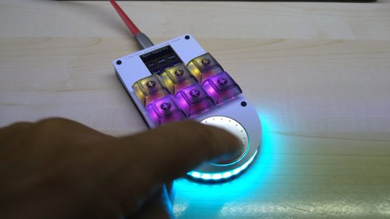
I found @iHayri1‘s keyboard in HackSpace magazine, issue #37, page 101. If you don’t happen to have it lying around – no problem! This magazine published by the Raspberry Pi Foundation gives away their digital version! While on the pricier end of the keyboards, it’s got a lot of interesting features. Six buttons, a media dial, an RGB LED under each key, a series of LED’s at the base of the keypad, and an LCD screen displaying each key’s current function. I would have ordered this one, except it’s been out of stock for a little while. :)
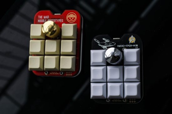
I found the NoodlePad by @TheMadNoodle on Etsy after searching for media keypads. This is another beautifully designed board – eight buttons, knurled metal knob, mounted onto a shaped board and thick lasercut acrylic plate. This was the first board I saw referencing “QMK” firmware. This board is also offered in a “semi-assembled” state where the buyer supplies their own switches and keycaps. If you’re going to fall down a rabbit hole on mechanical keyboards, the switches may be what get you. The ordering options also offer “Cherry Red,” “Cherry Blue,” “Cherry Brown,” and “Cherry Black” switches. At first I thought this referred only to the color of the switch underneath the keycap. As it turns out, each color matches the little bit of plastic connecting into the keycap which in turn is associated with a different set of mechanical features for that particular kind of switch. Maybe you want a key with more bounce, requires more force, or a more gentle touch. That you can order your keypad with the exact keys you need says a lot about this maker and their product.
I happened to catch @travis_the_makr showing off a prototype “BYO Keyboard” on Adafruit’s Show and Tell. I should probably feel a little bad for hassling Travis to sell me one of these board immediately after his appearance on the show. Intended as both a way to get started with soldering and programming as well as an actually useful final project. I kinda love the project is powered by an Adafruit Itsy Bitsy M0 so you can use either Arduino or CircuitPython. I note QMK firmware support is a stretch goal. :) Don’t let this bare bones DIY kit without LED’s, knobs, and displays fool you. If, like me, you’re only now embarking on your mechanical keypad journey and don’t have a drawer full of Cherry MX switches and keycaps, this is an excellent and affordable starting point. Suffice it to say, I immediately pledged the Kickstarter and am really looking forward to playing with this project.
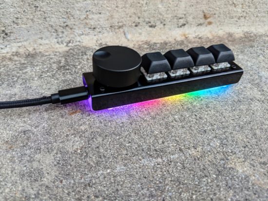
Of all the various keypads I’ve looked at, this was the very first one I ordered. I opted for the version with the black steel case, wonderfully heavy metal knob, and asked the owner for some variation in the keycaps. Craig shipped the keypad immediately and it arrived well packed in bubble wrap, only requiring that I pop in my choice of keycaps and apply the included sticky rubber feet.2 This keypad rocks four Cherry MX switches, a big hefty knurled metal knob, six RGB LED’s which glow through the lasercut acrylic base plate. My configuration (with the metal case) was $62, including shipping. While this is the only keypad I’ve actually used so far, it’s going to hard to top.
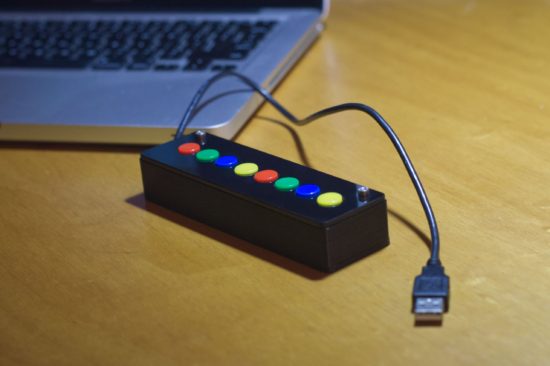
Once I started tweeting about picking out some keypads, my buddy Pete told me about the “8K Controller” by 2XLNetworks. This keypad has no LED’s, no metal knobs, no LCD displays – but it doesn’t need any of that. It comes with a built-in USB cable, you can order it with pre-programmed with custom button assignments at no extra cost, reprogram it if you like, and it unlike a hipster clicky-clacky Cherry MX switch, it rocks arcade buttons. If you need a bulletproof box that can stand up to repeated abuse at the hands of the public (perhaps for a photobooth, art project, school installation?), this is be the keyboard for you.
TLDR: I’m going to try some mechanical keyboards to help me work from home and blog about my experiences.
I’m fortunate that I’ve been able to work from home this pandemic. I’ve always made a special effort to make my work more “digital,” by scanning and organizing digital copies of important work documents. In many ways working from home hasn’t required too many changes to my overall workflow. My entire office and desk space shrunk to just a single laptop propped up on a plank of cardboard with some holes to help distribute heat. I have to be more disciplined about creating digital notes, since I can’t cover my work space in post-its and illegible scraps of paper. Two pairs of noise cancelling bluetooth headphones are are taking the place of four walls and a door to help me concentrate and communicate “I’m working” to the kids. 1 While I’ve gotten used to one medium sized laptop screen, in place of a dual monitor setup, the one thing that’s been extremely difficult is using a laptop keyboard instead of a full fledged keyboard.
Which brings me, dear reader, to the QMK or “quantum mechanical keyboards.” The QMK is a keyboard firmware2 that allows you to create very customized keyboards and keyboard layouts.
A while back I wrote a Chrome extension to help me with some work related data entry tasks. It works by intercepting some of the top row function keys, preventing their default actions, and replacing them with some macros. This setup probably slashed the number of required clicks and keystrokes by 75%. My fevered dream is for a custom keyboard which could cut this yet in half.
Now, if that keyboard also has some media controls and sweet RGB goodness, well, then, awesome. Of course, this means I can’t just go order a keyboard off a shelf. While there are plenty of neat custom and QMK keyboards, to really get the most out of a board, to get exactly what I need, I will need to roll up my sleeves and actually dive into the firmware itself.
If you don’t know who EMSL are, you’re missing out. Evil Mad Scientist Laboratories is a small family owned DIY electronics business in the California Bay Area with a deep enduring commitment and support for open source software, open source hardware, educators, and Makers.
And they are genuinely good people. Their blog is an incredible resource for anyone from beginners in crafts and electronics to grizzled veteran engineers. There are free tutorials, resources, and tons of kits for every level. I’ve purchased several of their kits and cannot recommend their products highly enough for the material quality, comprehensive (and occasionally playful) instructional materials, and support – including a robust community and forum.1
Since our family is home an awful lot these days, we’re always looking ways to keep our kids curious, engaged, and occupied. Our next project is the EMSL “BristleBot.”2
Their write up and video tutorial will provide you with all the information you need to help build a very tiny zippy robot from things you probably have around the house. 3 There’s a lot to talk about with your kids here – from basic electrical connections, off-center motors, springiness of the bristles, to how the directions of bristles affect the robot’s travel.
A box of parts to make enough for a whole classroom might be about $50 (or less) if you could buy parts in bulk. But, if you only need a handful of BristleBots for your household, you could taking things apart for motors, old toothbrushes for bristles, common coin cell batteries for free/nearly free, maybe adding some matchbox car or marble run tracks for BristleBot trails or a cardboard box for a battle arena.