Thermistor Tables

There are at least four thermistor tables out there to choose from.  Zach 1, Zach 2, Jet, and Tim.  The first time I updated my extruder board’s firmware with a new temperature table I used Jet’s and the second time I used Zach 1.  (The second time was because the extruder spark incident and almost certainly unrelated to Jet’s table).

My understanding is that Tim’s table has a higher “resolution,” meaning there’s a lot more resistance / temperature pairs.  However, I’ve been using Zach 1 without a problem so there’s no reason for me to switch.

Z axis warp… gone?

After finishing my printstruder (you can never have too many spare parts) I lowered the one warped Z axis threaded rod.  I probably lowered it about 1mm farther than it was before I had raised it to install the Z axis crank.

I guess sometimes that kind of thing makes a difference.  I’m watching my little ‘bot print up something right now… and it’s looking fantastic.  So far there’s no hint of the former regular but slight shift that you can see on the TARDIS and Dalek.  Mind, the TARDIS and Dalek are some of my best prints.  Anyhow, this is truly encouraging – with a nigh elimination of this warp, I am that much closer to printing precision parts.

One of the members on the MakerBot Operators group has posted his process for calibrating his ‘bot and adjusting Skeinforge settings.  It appears ridiculously thorough and I’m looking forward to trying it out.

New Print: Printstruder

Plastruder

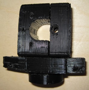
Printstruder

You can see how badly the cooling ABS warped on the base plate, especially on the left.  All of the parts, except perhaps the insulating retainer ring at the bottom, have a slight warp to them.  I expect most of my ABS prints will suffer from this to one degree or another until I install a heated build platform.  But, that’s a project for another day.

In these pictures you can also see the more pronounced effect of the warped Z axis threaded rod, again more prominent on the base plate.  The shifted layers occur approximately every 1mm or so.  As I’m less concerned with the cosmetic effect on a purely functional piece such as this, I didn’t bother adjusting this Z axis threaded rod until after I finished the prinstruder.

Prinstruder – all done

My little bot is just crank out parts today.  :)

I’ve finished the Idler Bracket v3, Motor Bracket v3, Base Plate v3, and Insulating Retainer.  After a little cleanup the parts fit together very well.  I think one of the most interesting parts about printing pieces designed by others is seeing some aspect of the 3D model that doesn’t really quite make sense – but once it’s printed out and fit together you understand the design decision.

Take, for instance, a little divot in the Motor Bracket v3. I didn’t get why it was there… until I fit the parts together.  I can now see that it’s purpose is to act as a cone to funnel and guide the plastic filament.  This is the sort of wonderful little nuance that can be produced as part of a 3D printed object that would probably be difficult, if not impossible, to recreate in a lasercut layer system such as the plastruder.

Z-Stage Threaded Rod Warp

When installing the Z stage threaded rods I noticed that one of them was particularly warped.  Overall, this hasn’t had much of an effect on my prints.  I put the warp-ier part end of the threaded rod down and this reduced the effect of the warp.  This lead to a visible shift in a layer about every 11mm or so.

I raised the warped threaded rod slightly in order to add Zaggo‘s Z axis crank.  However, I’ve discovered that this has apparently introduced more of the warped section of the threaded rod.  Now I’m seeing a visible shift in the layers every 1mm!

Non-ideal.

The Z axis crank is ridiculously useful, so I’ll need to lower the warped rod and raise one of the others.

Printstruder – second part

I’ve already started work on my prinstruder as designed by Zaggo.  I’ve printed up the Idler Bracket v3 and am now printing the Motor Bracket v3.  I think the printstruder assembly is probably better suited to an earlier version of the MakerBot – one that used a “small” and “large” dino.  My batch #9 bot uses two dinos – the “Big Dino” and the “Wierd Dino.”

However, I’d really like to have an extra plastruder/printstruder on hand … just in case.

Improved Y axis tensioner

I’m several iterations into my Y axis tensioner.  I think this newest version is a pretty good improvement.  I’m now on version 7 – and have put each part in its own file.  Here’s some information about the revisions:

  • The first printable version, #5 still used a single captive nut and bolt system.  The nut had to be a certain minimum distance from the center of the pulley axle in order to allow the pulley to turn freely.  However, this minimum distance also meant that the edge of the captive nut was too close to the edge of the stage – which wouldn’t allow the piece to be tightened.
  • Thus, I revised the piece so that it uses two captive nut/bolt parts – one on each side of the pulley.  This allows me to set the captive nut back far enough that it leave room for the piece to be tightened without running into the pulley.
  • I discovered that I had forgotten to measure one of the pieces of wood properly and ended up with a 3mm gap for the edge of the Y stage, rather than a 5mm gap.

I’ve printed up version 7, but haven’t had occasion to disassemble the Y stage yet.  The next time I do I’m installing this tensioner.  Time to design the X stage tensioner!

Current projects

Some of my current MakerBot related projects:

  • Trying to improve build quality.   I’m trying to tune up the hardware before I start to fiddle with Skeinforge in earnest.  I’d also like to replace one or more of my threaded rods as at least one has a warp significant enough to affect build quality.
  • Printable axis tensioners.  I want to design a set of tensioners for all three axes.  Right now I’ve got a draft for the Y axis that needs to be revised.
  • Printstruder.  I’ve finished the idler bracket, but still need to print all the rest of the parts.
  • Chess set.  Since I’ve got WAY more black ABS then the natural (off-white) color, I want to finish dialing in the print quality on the black ABS before I start print up the white pieces.
  • Chess/game board.  I’d like to design a modular board for printing out of ABS.  I’m thinking I would need three different kinds of pieces – corner, edge, and interior pieces.  I’m thinking of a connector system somewhere in-between a puzzle piece and laminate flooring, if that makes any sense at all.  Plus, being modular, you could store the pieces and board in a small box/bag.
Default Series Title

Upgrades

While trying to improve print quality by increasing belt tension on the X and Y axes, I did some routine maintenance.  I oiled the rods and tightened screws.  While I was at it, I took a look at my insulator retainer.  It had developed more two and a half cracks.  It had actually cracked all the way through one of the screw holes.  It was still working, but I’d rather not chance it failing while I’m printing.

So, I replaced it with one of my printed insulator retainers.  I gotta say, it feels really great to swap out a stock part for a part I built on my own ‘bot.  I suppose this is more of a repair than an upgrade… but I still choose to think of it as an upgrade.  :)

Axis Tensioner Y – first try

Obviously, this is an iterative process.  I revised my drawings of the axis tensioner for the Y axis a few times before trying to print it.  When I created the screenshot for it I noticed that some of the notches didn’t line up properly.  In any case, the part that fits around the pulley’s axle came out well while the part that fits on the Y stage edge didn’t come out very well, was fragile, and snapped when I was cleaning it up.  I’ll edit the file to thicken the wall of the Y axis edge piece and try it again.